• Infrared and Laser Engineering
  • Vol. 50, Issue 9, 20210056 (2021)
Nana Xu1、2, Feng Yu1、2、*, and Zhenhua Zhou1、2
Author Affiliations
  • 1Beijing Institute of Space Mechanics & Electricity, Beijing 100094, China
  • 2Beijing Key Laboratory of Advanced Optical Remote Sensing Technology, Beijing 100094, China
  • show less
    DOI: 10.3788/IRLA20210056 Cite this Article
    Nana Xu, Feng Yu, Zhenhua Zhou. Thermal design and validation of a geosynchronous orbit infrared camera[J]. Infrared and Laser Engineering, 2021, 50(9): 20210056 Copy Citation Text show less
    Schematic diagram of camera structure
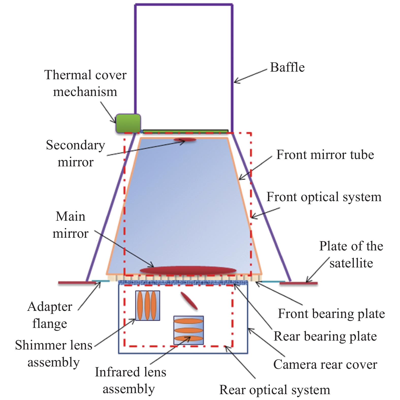
    Fig. 1. Schematic diagram of camera structure
    Variation curve of solar radiation heat flux on +Z side
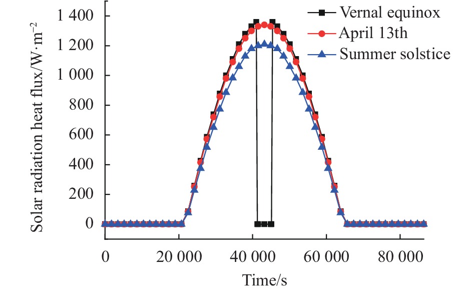
    Fig. 2. Variation curve of solar radiation heat flux on +Z side
    Diagram of minimum evasion angle
    Fig. 3. Diagram of minimum evasion angle
    Diagram of minimum evasion angle
    Fig. 4. Diagram of minimum evasion angle
    Thermal cover closing duration
    Fig. 5. Thermal cover closing duration
    Thermal analysis model
    Fig. 6. Thermal analysis model
    Temperature comparison of main optical system with different schemes
    Fig. 7. Temperature comparison of main optical system with different schemes
    Schematic diagram of detector assembly
    Fig. 8. Schematic diagram of detector assembly
    Schematic diagram of heat dissipation path
    Fig. 9. Schematic diagram of heat dissipation path
    ComponentsHeat load/WWorking time
    Optical path switching and focusing motor, etc15Short time (1-2 min/d)
    Focal plane circuit box2Long time (>20 h/d)
    Video processor18Long time (>20 h/d)
    Power box15Long time (>20 h/d)
    Refrigerator50Long time (>20 h/d)
    Shimmer focusing and circuit box10Short time (<5 min/d)
    Table 1. Internal heat source distribution of the camera
    ComponentsTemperature requirement
    Survival case/℃Imaging case/℃
    Baffle≤100≤100
    Main bearing structure>020±3
    Main optical system>1220±3
    Rear optical system>1220±5
    Hot end and compressor of the refrigerator−20-23−20-23
    Video processor and power box−20-55−20-55
    Shimmer circuit box0-500-50
    Thermal cover mechanism0-700-70
    Table 2. Temperature demand of the camera components
    CasesSpace heat flowBoundaryWorking mode
    Survival case0Low temperatureSurvival mode,all the heat sources are off
    Low temperature caseInitial stage of vernal equinoxLow temperatureStandby mode, only the refrigerator is on
    High temperature caseFinal stage of summer solsticeHigh temperatureImaging mode, all the heat sources are on
    Table 3. Ground test cases
    ComponentsTransfer orbit (Survival mode)Geosynchronous orbit
    Ground test temperature/℃On-orbit temperature/℃Ground test temperature/℃On-orbit temperature/℃
    Main mirror13.59-13.6213.5-13.917.75-19.9117.7-20.6
    Secondary mirror14.2-14.2214.3-14.618.68-20.0818.5-21.5
    Main bearing structure15.02-15.3315.1-15.320.01-21.9920.0-20.7
    Rear optical system13.8-14.214.3-14.418.6-20.619.2-20.0
    Compressor−2.37- −2.35−2.8- −2.55.44-8.443.5-6.5
    Hot end−3.58- −3.56−4.16- −3.98.33-13.054.9-6.8
    Video processor−3.17- −3.15−3.2- −2.81.95-14.521.5-13.5
    Power box−4.1- −4.0−4.0- −3.91.12-6.730.6-5.4
    Shimmer circuit box14.7-14.914.5-14.719.79-27.6719.4-27.5
    Thermal cover mechanism4-146.7-12.710.2-24.18.0-22.1
    Table 4. Temperature date of ground test and on- orbit
    Nana Xu, Feng Yu, Zhenhua Zhou. Thermal design and validation of a geosynchronous orbit infrared camera[J]. Infrared and Laser Engineering, 2021, 50(9): 20210056
    Download Citation