
Zhentang Zhao, Dong Wang, Lixin Yin, Guoping Fang, Qiang Gu, Ming Gu, Yongbin Leng, Bo Liu, Qiaogen Zhou, Liren Shen, Meng Zhang, Haixiao Deng, Jiahua Chen, Jianhui Chen, Zhihao Chen, Jianguo Ding, Wencheng Fang, Chao Feng, Duan Gu, Xiao Hu, Dazhang Huang, Maomao Huang, Zhiqiang Jiang, Bin Li, Guoqiang Lin, Yiyong Liu, Sen Sun, Guanghong Wang, Xingtao Wang, Zhen Wang, Yanqing Wu, Luyang Yu, Qibing Yuan, Wei Zhang, Shaopeng Zhong, Xiaobin Xia, Chuanxiang Tang, Wenhui Huang, Yingchao Du, Lixin Yan. Shanghai Soft X-ray Free-Electron Laser Test Facility[J]. Acta Optica Sinica, 2021, 41(1): 0114006
- Acta Optica Sinica
- Vol. 41, Issue 1, 0114006 (2021)
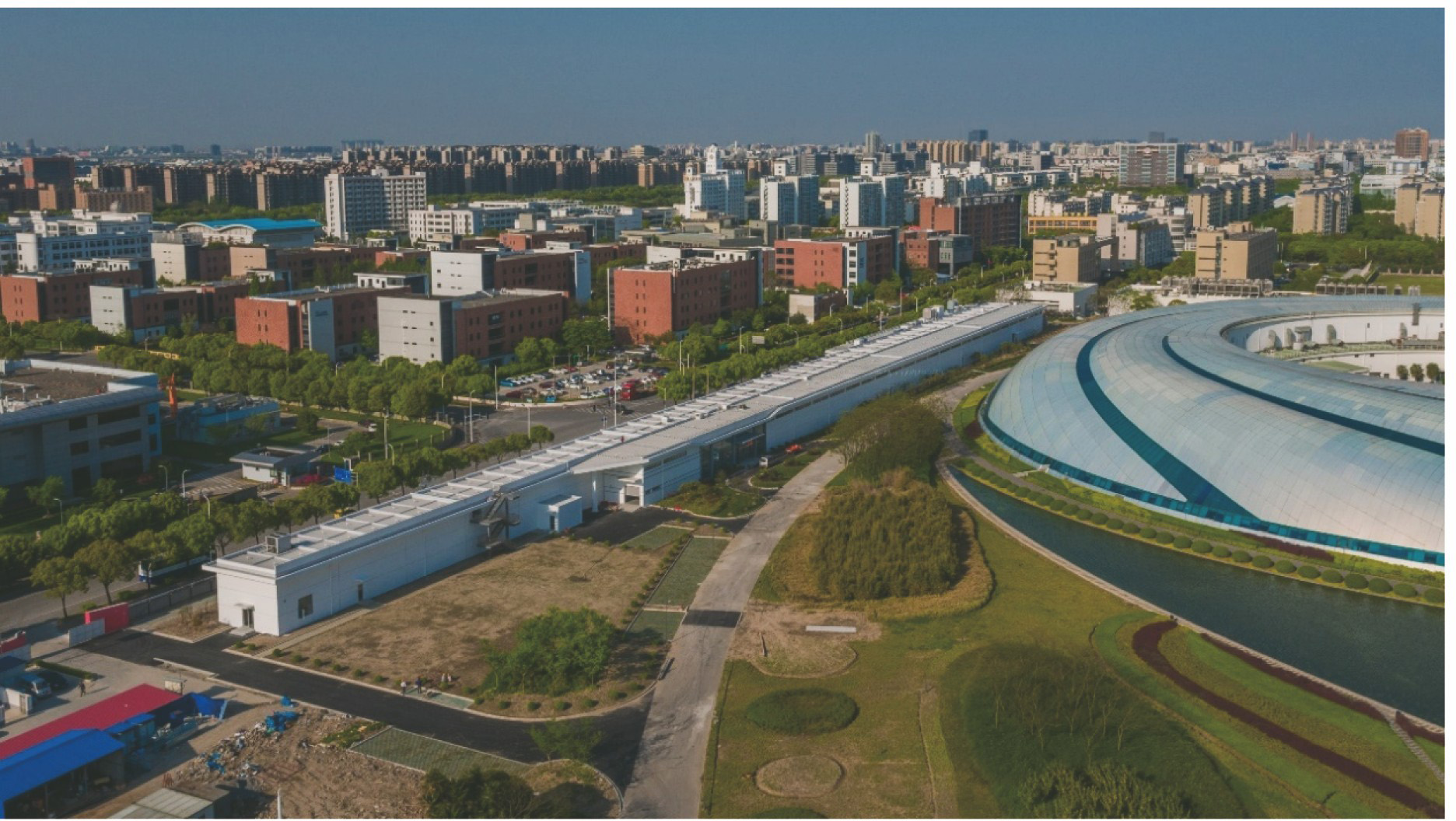
Fig. 1. SXFEL test facility in the SSRF campus
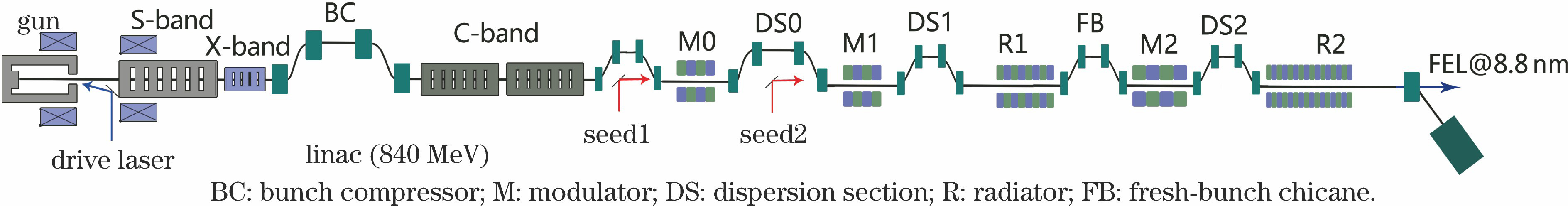
Fig. 2. Schematic layout of SXFEL test facility
Fig. 3. Schematic of the undulator system for HGHG cascade
Fig. 4. Gain curve and output spectra of 8.8 nm cascaded HGHG-FEL. (a) Gain curve; (b) output spectra
Fig. 5. Schematic of the undulator system for EEHG-HGHG cascade
Fig. 6. Gain curve and output spectra of the first stage EEHG. (a) Gain curve; (b) output spectra
Fig. 7. Second stage gain curve of EEHG-HGHG cascade
Fig. 8. Schematic of the undulator system for single stage EEHG
Fig. 9. Gain curve (20th harmonic) and radiation spot (30th harmonic) of single-stage EEHG. (a) Gain curve; (b) radiation spot
Fig. 10. Injector of the SXFEL test facility
Fig. 11. Laser heater. (a) Sketch; (b) physical photograph
Fig. 12. X-band linearizer
Fig. 13. Movable magnetic bunch compressor. (a) Sketch; (b) physical photograph
Fig. 14. Longitudinal phase space and current distribution of electron beam at the linac exit. (a) Without X-band linearizer; (b) with X-band linearizer
Fig. 15. C-band linac
Fig. 16. C-band deflecting cavity at the exit of the SXFEL linac and the measured longitudinal beam phase space distribution. (a) C-band deflecting cavity; (b) longitudinal beam phase space distribution
Fig. 17. U235 undulators installed in tunnel
Fig. 18. Cavity beam position monitor. (a) Photograph of the monitor; (b) resolution evaluation result
Fig. 19. X-band deflecting structures installed in the SXFEL test facility. (a) Photograph; (b) measured beam phase space when lasing
Fig. 20. High resolution X-ray spectrometer in diagnostic beam line. (a) Photograph; (b) measured spectrum
Fig. 21. Schematic of the SXFEL user facility
|
Table 1. Main parameters of the SXFEL linac
|
Table 2. Main FEL parameters of the SXFEL test facility
|
Table 3. Undulator parameters in the SXFEL test facility
|
Table 4. Seed laser parameters in the SXFEL test facility
|
Table 5. Beam and optical diagnostic systems and their main parameters at undulator section
| ||||||||||||||||||||||||||||||
Table 6. Design parameters of the SXFEL user facility


Set citation alerts for the article
Please enter your email address

© Copyright 2018-2021 | Chinese Laser Press. All Rights Reserved 沪ICP备15018463号-20