
Yu Xie, Dawei Cai, Hao Wu, Jing Pan, Ning Zhou, Chenguang Xin, Shaoliang Yu, Pan Wang, Xiaoshun Jiang, Jianrong Qiu, Xin Guo, Limin Tong. Mid-infrared chalcogenide microfiber knot resonators[J]. Photonics Research, 2020, 8(4): 616
- Photonics Research
- Vol. 8, Issue 4, 616 (2020)
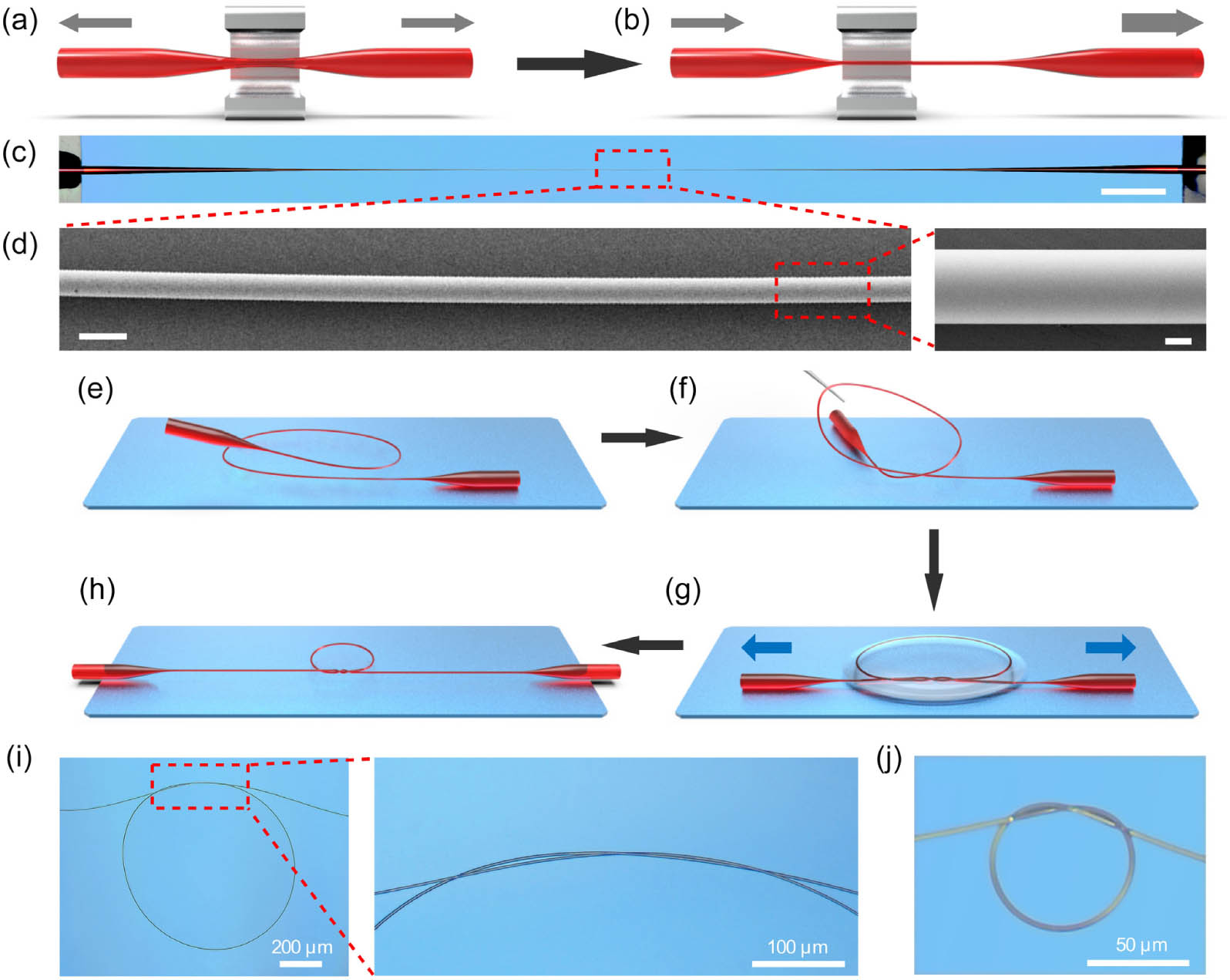
Fig. 1. Fabrications of ChG microfibers and ChG MKRs. (a) and (b) Schematic illustrations of fabrication of a ChG microfiber with controllable waist length and diameter. (c) Optical micrograph of a biconically tapered ChG fiber consisting of a 5.6 μm diameter, 5 mm length ChG microfiber at the central area, and 14 mm length taper area connected to 250 μm diameter initial fiber at both ends. Scale bar, 2 mm. (d) Scanning electron microscope (SEM) image of the microfiber showing the high diameter uniformity. Scale bar, 10 μm. Inset: close-up SEM image of the microfiber, showing excellent sidewall smoothness of the microfiber. Scale bar, 2 μm. (e)–(h) Schematic illustrations of assembly of a ChG MKR in liquid. (i) Optical micrograph of an as-assembled 824 μm diameter ChG MKR using a 3.2 μm diameter ChG microfiber. Inset: close-up optical micrograph of the intertwisted overlap area with an effective coupling length of about 200 μm. (j) Optical micrograph of a 62 μm diameter ChG MKR assembled from a 3.5 μm diameter ChG microfiber.
![Mid-IR characterization of a ChG MKR. (a) Schematic illustration of the experimental setup. QCL, quantum cascade laser; CO, free space control optics including polarization controllers (Edmund Optics, 62-770) and homemade silica glass optical attenuators; L1 (L2), ZnSe lens. (b) Typical transmission spectrum of an 824 μm diameter MKR [the one shown in Fig. 1(i)]. (c) Close-up view of the transmission spectrum from 4605 to 4620 nm wavelength, with a measured FSR of about 3.1 nm. (d) Lorentzian fitting (red curve) to a resonance mode (black dots) centered at 4469.14 nm wavelength.](/richHtml/prj/2020/8/4/04000616/img_002.jpg)
Fig. 2. Mid-IR characterization of a ChG MKR. (a) Schematic illustration of the experimental setup. QCL, quantum cascade laser; CO, free space control optics including polarization controllers (Edmund Optics, 62-770) and homemade silica glass optical attenuators; L1 (L2), ZnSe lens. (b) Typical transmission spectrum of an 824 μm diameter MKR [the one shown in Fig. 1(i) ]. (c) Close-up view of the transmission spectrum from 4605 to 4620 nm wavelength, with a measured FSR of about 3.1 nm. (d) Lorentzian fitting (red curve) to a resonance mode (black dots) centered at 4469.14 nm wavelength.
Fig. 3. Spectral tunability of the mid-IR ChG MKRs. (a) Typical transmission spectra of a ChG MKR with diameter decreased successively from (1) 1336 μm to (2) 749 μm and (3) 281 μm by tightening the knot structure in liquid, resulting in the FSR increasing from 2.0 to 3.3 and 9.6 nm, correspondingly. (b) Resonance peak wavelength shift of an 824 μm diameter MKR [the one shown in Fig. 1(i) ] with the temperature rising from 31.4°C to 59.8°C, leading to a temperature tuning ratio of 110 pm · ° C − 1
Fig. 4. Mid-IR characterization of a PMMA-embedded on-chip ChG MKR. (a) Schematic illustration of a PMMA-embedded on-chip ChG MKR. (b) Optical micrograph of a PMMA-embedded 551 μm diameter ChG MKR assembled from a 3.4 μm diameter microfiber. (c) Transmission spectrum of the embedded MKR shown in (b), with a measured FSR of 4.2 nm and a Q 1.1 × 10 4

Set citation alerts for the article
Please enter your email address
© Copyright 2018-2021 | Chinese Laser Press. All Rights Reserved 沪ICP备15018463号-20