• Laser & Optoelectronics Progress
  • Vol. 60, Issue 9, 0900001 (2023)
Yunqi Liu1、*, Chen Jiang1, Zuyao Liu1、2, and Xinyi Zhao1、3
Author Affiliations
  • 1Key Laboratory of Specialty Fiber Optics and Optical Access Networks, Ministry of Education, School of Communication and Information Engineering, Shanghai University, Shanghai 200444, China
  • 2Key Laboratory of Optoelectronic and Telecommunication of Jiangxi Province, School of Physics and Communication Electronics, Jiangxi Normal University, Nanchang 330022, Jiangxi, China
  • 3Henan Key Laboratory of Optoelectronic Sensing Integrated Application, College of Electronic and Electrical Engineering, Henan Normal University, Xinxiang 453007, Henan, China
  • show less
    DOI: 10.3788/LOP220735 Cite this Article Set citation alerts
    Yunqi Liu, Chen Jiang, Zuyao Liu, Xinyi Zhao. Long-Period Fiber Gratings[J]. Laser & Optoelectronics Progress, 2023, 60(9): 0900001 Copy Citation Text show less
    Schematic diagram of LPFG
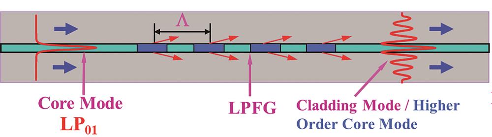
    Fig. 1. Schematic diagram of LPFG
    LPFG. (a) Three-layer structure model; (b) transverse refractive index
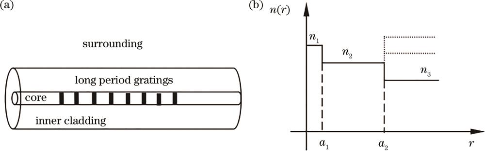
    Fig. 2. LPFG. (a) Three-layer structure model; (b) transverse refractive index
    Change of effective refractive index of core fundamental mode with wavelength
    Fig. 3. Change of effective refractive index of core fundamental mode with wavelength
    Intensity distributions of the 8 lower order core modes
    Fig. 4. Intensity distributions of the 8 lower order core modes
    Change of effective refractive index of cladding modes with wavelength for the first 19 times before the first diffraction order
    Fig. 5. Change of effective refractive index of cladding modes with wavelength for the first 19 times before the first diffraction order
    Intensity distributions of four low order cladding modes excited by circularly symmetric refractive index modulation of LPFG across the fiber cross-section
    Fig. 6. Intensity distributions of four low order cladding modes excited by circularly symmetric refractive index modulation of LPFG across the fiber cross-section
    Variation of coupling constants between fundamental core mode and cladding mode on the cladding mode order
    Fig. 7. Variation of coupling constants between fundamental core mode and cladding mode on the cladding mode order
    Transmission spectra and mode pattern of LPFG fabricated in B-Ge-codoped single-mode fiber
    Fig. 8. Transmission spectra and mode pattern of LPFG fabricated in B-Ge-codoped single-mode fiber
    Phase matching curves of the cladding modes of LPFG. (a) LP02 mode to LP0,20 mode; (b) LP0,11 mode to LP0,20 mode
    Fig. 9. Phase matching curves of the cladding modes of LPFG. (a) LP02 mode to LP0,20 mode; (b) LP0,11 mode to LP0,20 mode
    Schematic diagram of the LPFG inscription by the UV laser techniques. (a) Amplitude mask exposure technique; (b) point by point inscribing method[19]
    Fig. 10. Schematic diagram of the LPFG inscription by the UV laser techniques. (a) Amplitude mask exposure technique; (b) point by point inscribing method[19]
    Typical transmission spectrum of a carbon dioxide laser written LPFG in a commercial B-Ge-codoped fiber (together with an image of the near-field pattern of the coupled LP cladding mode at the resonance wavelength of 1531 nm)[7]
    Fig. 11. Typical transmission spectrum of a carbon dioxide laser written LPFG in a commercial B-Ge-codoped fiber (together with an image of the near-field pattern of the coupled LP cladding mode at the resonance wavelength of 1531 nm)[7]
    Schematic diagram of the experimental setup for the fabrication of helical LPFG with carbon dioxide laser[30]
    Fig. 12. Schematic diagram of the experimental setup for the fabrication of helical LPFG with carbon dioxide laser[30]
    Schematic diagram of experimental setup for LPFG fabrication technique with femtosecond laser[41]
    Fig. 13. Schematic diagram of experimental setup for LPFG fabrication technique with femtosecond laser[41]
    Schematic diagram of arc-induced LPFG[47]
    Fig. 14. Schematic diagram of arc-induced LPFG[47]
    Side view of a mechanically induced LPFG[52]
    Fig. 15. Side view of a mechanically induced LPFG[52]
    Transmission spectra of mechanically induced LPFG with increasing applied pressure[52]
    Fig. 16. Transmission spectra of mechanically induced LPFG with increasing applied pressure[52]
    Schematic diagram of HF etched LPFG[58]
    Fig. 17. Schematic diagram of HF etched LPFG[58]
    Evolution of transmission spectra when strain is applied to the etched LPFG[58]
    Fig. 18. Evolution of transmission spectra when strain is applied to the etched LPFG[58]
    Schematic diagram of the experimental setup for fabrication of the micro-tapered LPFG[66]
    Fig. 19. Schematic diagram of the experimental setup for fabrication of the micro-tapered LPFG[66]
    Schematic diagram of experiment. (a) Schematic of alignment of metal mask and fiber; (b) cross section of optical fiber after He ion implantation[71]
    Fig. 20. Schematic diagram of experiment. (a) Schematic of alignment of metal mask and fiber; (b) cross section of optical fiber after He ion implantation[71]
    Schematic diagram of the acoustic induced LPFG[77]
    Fig. 21. Schematic diagram of the acoustic induced LPFG[77]
    Dependence of the grating contrast on the laser scanning cycle of carbon dioxide laser when the fiber is applied with external strain during the fabrication of the LPFG[26]
    Fig. 22. Dependence of the grating contrast on the laser scanning cycle of carbon dioxide laser when the fiber is applied with external strain during the fabrication of the LPFG[26]
    Schematic diagram of the relation between glass volume and heating temperature for the fiber being heated and cooled at different conditions[7]
    Fig. 23. Schematic diagram of the relation between glass volume and heating temperature for the fiber being heated and cooled at different conditions[7]
    Dual-dip resonance of LPFG at dispersion turning point
    Fig. 24. Dual-dip resonance of LPFG at dispersion turning point
    Transmission spectra of LPFG. (a) Single LPFG; (b) cascaded LPFGs [86]
    Fig. 25. Transmission spectra of LPFG. (a) Single LPFG; (b) cascaded LPFGs [86]
    Temperature characteristics of conventional LPFG with LP06 cladding mode[86]
    Fig. 26. Temperature characteristics of conventional LPFG with LP06 cladding mode[86]
    Temperature characteristics of coated LPFG with LP06 cladding mode. (a) Silicone rubber; (b) UV curing adhesive[86]
    Fig. 27. Temperature characteristics of coated LPFG with LP06 cladding mode. (a) Silicone rubber; (b) UV curing adhesive[86]
    LPFG inscribed in photonic crystal fiber by carbon dioxide laser[24]
    Fig. 28. LPFG inscribed in photonic crystal fiber by carbon dioxide laser[24]
    Strain characteristics of the carbon dioxide laser written LPFG with parallel inclined planes[92]
    Fig. 29. Strain characteristics of the carbon dioxide laser written LPFG with parallel inclined planes[92]
    Strain characteristics of the fast and slow axis modes of the helical LPFG written in polarization-maintaining fiber[33]
    Fig. 30. Strain characteristics of the fast and slow axis modes of the helical LPFG written in polarization-maintaining fiber[33]
    Bending characteristics of cascaded tilted long-period fiber gratings[97]
    Fig. 31. Bending characteristics of cascaded tilted long-period fiber gratings[97]
    Structure of concave-lens-like long-period fiber grating[99]
    Fig. 32. Structure of concave-lens-like long-period fiber grating[99]
    Bending characteristics of the LPFG written in the polarization-maintaining fiber. (a) Fast axis mode; (b) slow axis mode
    Fig. 33. Bending characteristics of the LPFG written in the polarization-maintaining fiber. (a) Fast axis mode; (b) slow axis mode
    Twist characteristics of the LPFG inscribed in the double-cladding fiber by carbon dioxide laser[101]
    Fig. 34. Twist characteristics of the LPFG inscribed in the double-cladding fiber by carbon dioxide laser[101]
    Twist characteristics of two-mode fiber LPFG. (a) Conventional LPFG; (b) tilted LPFGs[9]
    Fig. 35. Twist characteristics of two-mode fiber LPFG. (a) Conventional LPFG; (b) tilted LPFGs[9]
    Twist characteristics of two-mode fiber LPFG. (a) Helical LPFG[30]; (b) chiral LPFG[32]
    Fig. 36. Twist characteristics of two-mode fiber LPFG. (a) Helical LPFG[30]; (b) chiral LPFG[32]
    Twist characteristics of polarization-maintaining fiber LPFG[33]
    Fig. 37. Twist characteristics of polarization-maintaining fiber LPFG[33]
    SRI characteristics of LPFG near dispersion turning point[6]
    Fig. 38. SRI characteristics of LPFG near dispersion turning point[6]
    Relationship between fiber cladding diameter and the period of LPFG[114]
    Fig. 39. Relationship between fiber cladding diameter and the period of LPFG[114]
    SRI characteristics of the LPFG written in the thin-cladding fiber[114]
    Fig. 40. SRI characteristics of the LPFG written in the thin-cladding fiber[114]
    SRI characteristics of LPFG before and after the etching[115]
    Fig. 41. SRI characteristics of LPFG before and after the etching[115]
    The pH sensing characteristics of the PAH/PAA-coated LPFGs with and without clad etching[115]
    Fig. 42. The pH sensing characteristics of the PAH/PAA-coated LPFGs with and without clad etching[115]
    Schematic diagram of oxide film coated LPFG for environmental refractive index sensing[118]
    Fig. 43. Schematic diagram of oxide film coated LPFG for environmental refractive index sensing[118]
    SEM picture of the cross section of the LPFG coated with Al2O3 nano-film[27]
    Fig. 44. SEM picture of the cross section of the LPFG coated with Al2O3 nano-film[27]
    SRI characteristics of LPFG coating with Al2O3 nano film[27]
    Fig. 45. SRI characteristics of LPFG coating with Al2O3 nano film[27]
    SRI characteristics of LPFG coating with TiO2 nano film[122]
    Fig. 46. SRI characteristics of LPFG coating with TiO2 nano film[122]
    SEM images of the coated LPFG. (a) Fiber coated with pure PVA film; (b) fiber coated with PEG/PVA composite film; (c) cross-section of the coated LPFG; (d) film thickness of the coated film[123]
    Fig. 47. SEM images of the coated LPFG. (a) Fiber coated with pure PVA film; (b) fiber coated with PEG/PVA composite film; (c) cross-section of the coated LPFG; (d) film thickness of the coated film[123]
    Dependence of the resonance wavelength under the ascending and descending humidity process of PEG/PVA coated LPFG[123]
    Fig. 48. Dependence of the resonance wavelength under the ascending and descending humidity process of PEG/PVA coated LPFG[123]
    Experimental setup of magnetic field sensor based on LPFG and magnetic fluid[124]
    Fig. 49. Experimental setup of magnetic field sensor based on LPFG and magnetic fluid[124]
    Transverse profile schematic diagram of thin cladding polarization maintaining fiber immersion into magnetic fluid[125]
    Fig. 50. Transverse profile schematic diagram of thin cladding polarization maintaining fiber immersion into magnetic fluid[125]
    Magnetic field characteristics of thin cladding polarization maintaining fiber immersion into magnetic fluid. (a) Fast axis mode; (b) slow axis mode[125]
    Fig. 51. Magnetic field characteristics of thin cladding polarization maintaining fiber immersion into magnetic fluid. (a) Fast axis mode; (b) slow axis mode[125]
    Diagram of the cascaded LPFG interferometer and spectrum of the interferometer[126]
    Fig. 52. Diagram of the cascaded LPFG interferometer and spectrum of the interferometer[126]
    Schematic diagram of cascaded coated long period fiber grating interferometer[83]
    Fig. 53. Schematic diagram of cascaded coated long period fiber grating interferometer[83]
    Transmission spectra of cascaded polarization-maintaining fiber LPFG
    Fig. 54. Transmission spectra of cascaded polarization-maintaining fiber LPFG
    Sensing characteristics of cascaded polarization-maintaining fiber LPFGs. (a) Temperature; (b) strain
    Fig. 55. Sensing characteristics of cascaded polarization-maintaining fiber LPFGs. (a) Temperature; (b) strain
    Schematic diagram of EDFA gain spectrum based on LPFG gain equalizer[129]
    Fig. 56. Schematic diagram of EDFA gain spectrum based on LPFG gain equalizer[129]
    LPFG. (a) Schematic of two and three phase-shifted LPFGs; (b) illustration of passband characteristics of filters based on LPFGs[133]
    Fig. 57. LPFG. (a) Schematic of two and three phase-shifted LPFGs; (b) illustration of passband characteristics of filters based on LPFGs[133]
    Tunable all-fiber band rejection filters. (a) Schematic of the bandwidth-tunable all-fiber band rejection filters based on a carbon dioxide laser-induced helicoidal LPFG pair of opposite helicities; (b) spectral characteristic of the fabricated bandwidth-tunable all-fiber band rejection filters according to the rotation angle [136]
    Fig. 58. Tunable all-fiber band rejection filters. (a) Schematic of the bandwidth-tunable all-fiber band rejection filters based on a carbon dioxide laser-induced helicoidal LPFG pair of opposite helicities; (b) spectral characteristic of the fabricated bandwidth-tunable all-fiber band rejection filters according to the rotation angle [136]
    Tunable bandwidth all-fiber rejection filters. Schematic diagrams of (a1) LPFG; (a2) R-LPFG; (b) spectral characteristics[138]
    Fig. 59. Tunable bandwidth all-fiber rejection filters. Schematic diagrams of (a1) LPFG; (a2) R-LPFG; (b) spectral characteristics[138]
    Cascaded helical LPFGs written by carbon dioxide laser[34]
    Fig. 60. Cascaded helical LPFGs written by carbon dioxide laser[34]
    Top view of the V groove holder that was used to keep part of the helical LPFG simmered in oil[141]
    Fig. 61. Top view of the V groove holder that was used to keep part of the helical LPFG simmered in oil[141]
    Experimental diagram of fabrication of acousto-optic grating and generation of first order OAM [143]
    Fig. 62. Experimental diagram of fabrication of acousto-optic grating and generation of first order OAM [143]
    Far field patterns measured at the output of the acousto-optic mode converter. (a) LP01 mode; (b) LP11 mode; (c) LP21 mode; (d) LP02 mode[145]
    Fig. 63. Far field patterns measured at the output of the acousto-optic mode converter. (a) LP01 mode; (b) LP11 mode; (c) LP21 mode; (d) LP02 mode[145]
    Experimental setup. (a) Experimental equipment diagram of fabrication of micro-bending grating and generation of OAM; (b) transmission spectrum of LP01-LP11 mode converter by the grating; (c) pattern and interference pattern of 1st order OAM [146]
    Fig. 64. Experimental setup. (a) Experimental equipment diagram of fabrication of micro-bending grating and generation of OAM; (b) transmission spectrum of LP01-LP11 mode converter by the grating; (c) pattern and interference pattern of 1st order OAM [146]
    LPFG. (a) Spectrum of the LPFG with 15-period gratings; (b) mode field distribution at different wavelengths[149]
    Fig. 65. LPFG. (a) Spectrum of the LPFG with 15-period gratings; (b) mode field distribution at different wavelengths[149]
    Spot pattern and interference pattern at the output of (a) LPFG and (b) tilted LPFG[9]
    Fig. 66. Spot pattern and interference pattern at the output of (a) LPFG and (b) tilted LPFG[9]
    Mode converter based on LPFG. (a) Spectrum of a single mode converter based on a LPFG; (b) mode field distribution and interference pattern of a single mode converter; (c) spectrum of the cascaded mode converter; (d) intensity distribution and interference patterns of the cascaded mode converter [150]
    Fig. 67. Mode converter based on LPFG. (a) Spectrum of a single mode converter based on a LPFG; (b) mode field distribution and interference pattern of a single mode converter; (c) spectrum of the cascaded mode converter; (d) intensity distribution and interference patterns of the cascaded mode converter [150]
    OAM mode converter based on PCF. (a) Interference patterns of the OAM+6 mode generated by the helical PCF; (b) interference patterns of the OAM+5 mode generated by the helical PCF [36]
    Fig. 68. OAM mode converter based on PCF. (a) Interference patterns of the OAM+6 mode generated by the helical PCF; (b) interference patterns of the OAM+5 mode generated by the helical PCF [36]
    Transmission spectra and intensity distributions of the PM-PCF [151]
    Fig. 69. Transmission spectra and intensity distributions of the PM-PCF [151]
    (a) Schematic diagram of the cascaded few-mode fiber LPFGs; (b) transmission spectra of the cascaded few-mode fiber LPFGs with different grating periods in 1.55 μm and 2 μm waveband[154]
    Fig. 70. (a) Schematic diagram of the cascaded few-mode fiber LPFGs; (b) transmission spectra of the cascaded few-mode fiber LPFGs with different grating periods in 1.55 μm and 2 μm waveband[154]
    LPFG-based polarizer. (a) PDL; (b) polarization extinction ratio[160]
    Fig. 71. LPFG-based polarizer. (a) PDL; (b) polarization extinction ratio[160]
    Transmission spectra of a 48 mm 45° TFG measured using a single wavelength at 1550 nm at two orthogonal polarization states (P1 and P2) [163]
    Fig. 72. Transmission spectra of a 48 mm 45° TFG measured using a single wavelength at 1550 nm at two orthogonal polarization states (P1 and P2) [163]
    PDL and transmission spectra of helical LPFG with a polarization-preserving fiber LPFG with a period of 480 μm [33]
    Fig. 73. PDL and transmission spectra of helical LPFG with a polarization-preserving fiber LPFG with a period of 480 μm [33]
    Principle of operation of the wavelength-selective coupler based on LPFG [165]
    Fig. 74. Principle of operation of the wavelength-selective coupler based on LPFG [165]
    Evanescent-field coupling between a LPFG and an identical bare fiber and mode distributions
    Fig. 75. Evanescent-field coupling between a LPFG and an identical bare fiber and mode distributions
    Design of broadband coupler based on three parallel identical LPFGs [169]
    Fig. 76. Design of broadband coupler based on three parallel identical LPFGs [169]
    Schematics of a voltage-controllable coupler based on two LPFGs with divided coil heaters[171]
    Fig. 77. Schematics of a voltage-controllable coupler based on two LPFGs with divided coil heaters[171]
    Add-drop multiplexer using two mode couplers based on LPFGs [165]
    Fig. 78. Add-drop multiplexer using two mode couplers based on LPFGs [165]
    Wavelength-tunable add/drop multiplexer by using four identical LPGs and PZT fiber stretchers [172]
    Fig. 79. Wavelength-tunable add/drop multiplexer by using four identical LPGs and PZT fiber stretchers [172]
    Total conversion ratio of MADMs for LP02 mode and LP03 mode[174]
    Fig. 80. Total conversion ratio of MADMs for LP02 mode and LP03 mode[174]
    Fabrication methodMechanismAdvantage and disadvantageReference
    UV laser techniquePhotosensitivityHigh writing efficiency,good repeatability,need amplitude mask and photosensitive fiber,and low temperature stability2],[14-19
    Carbon dioxide laser techniqueResidual stress relaxation,glass structure changes,physical deformationHigh writing efficiency,good flexibility and repeatability,no need of photosensitive fiber,high temperature stability,and low cost20-28
    Femtosecond laser techniqueMultiple photon absorption,glass structure changesGood flexibility and repeatability,no need of photosensitive fiber,high temperature stability,and high cost41-45
    Arc-induced LPFGResidual stress relaxation,glass structure changes,physical deformationGood flexibility,no need of photosensitive fiber,high temperature stability,and low cost46-51
    Mechanically induced LPFGPhotoelastic effectGood flexibility,grating degeneration,and low cost52-57
    Cladding etched LPFGPhysical deformation,residual stress relaxationHigh coupling efficiency,high sensitivity,and fragile fiber58-62
    Micro-tapered LPFGPhysical deformation,residual stress relaxationHigh sensitivity,fragile fiber,and low cost63-70
    Ion implanted LPFGIon implantationHigh index modulation,and asymmetric index distribution71-73
    Acoustic induced LPFGPhotoelastic effectGood flexibility,and low index modulation74-79
    Table 1. Comparison of the methods for LPFG fabrication
    Package materialModeSensitivity /(pm·℃-1Temperature /℃Reference
    Bare LPFGLP06 mode8220-14086
    PDMSLP05 mode255.420-8091
    Silicone rubberLP06 mode18620-14090
    UV Curable adhesiveLP06 mode543020-3086
    Table 2. Temperature characteristics of the LPFGs coated by different materials
    Fiber typeGrating typeModeSensitivity /(nm·rad-1·m-1Reference
    Single mode fiberConventional LPFGLP17 cladding mode0.0008104
    Single mode fiberHelical LPFGLP14 cladding mode-0.099105
    Dispersion shift fiberHelical LPFGLP14 cladding mode-0.038105
    Single mode fiberChiral LPFGLP14 cladding mode-0.207102
    Double cladding fiberConventional LPFGLP15 cladding mode0.088101
    Double cladding fiberHelical LPFGLP15 cladding mode-0.384106
    Two mode fiberConventional LPFGLP11 core mode0.379
    Two mode fiberHelical LPFGLP11 core mode0.4730
    Two mode fiberChiral LPFGLP11 core mode0.776832
    Table 3. Torsion characteristics of different kinds of LPFGs written by carbon dioxide laser
    Cascaded LPFGsSpecificationReference
    Helical LPFG pair with opposite helicities and same grating periodBandwidth tunable,15 dB bandwidth > 27 nm,grating length > 10 cm,and polarization insensitive136
    Cascaded LPFGs with different grating periodsTheoretical calculation137
    Cascaded gratings consists of conventional and helical LPFGsGrating length < 5.13 cm,bandwidth tunable,15 dB bandwidth > 16.3 nm,and PDL < 0.9 dB138
    Helical LPFG pair with opposite helicities and same grating periodGrating length < 4.6 cm,and 1 dB bandwidth > 15 nm34
    Helical LPFG pair with opposite helicities and different grating periodsGrating length is 5.02 cm,1 dB bandwidth > 13 nm,and dependent on the incident polarization35
    Helical LPFG pair with opposite helicities,combined with a cladding-mode stripper1 dB bandwidth is 14 nm,and polarization insensitive141
    Table 4. Comparison of cascaded long period fiber gratings
    Yunqi Liu, Chen Jiang, Zuyao Liu, Xinyi Zhao. Long-Period Fiber Gratings[J]. Laser & Optoelectronics Progress, 2023, 60(9): 0900001
    Download Citation