• Photonics Research
  • Vol. 4, Issue 6, 322 (2016)
Yaofei Chen1、2, Tiegen Liu1、3、4, Qun Han1、*, Wenchuan Yan1, and Lin Yu1
Author Affiliations
  • 1College of Precision Instrument and Opto-Electronics Engineering, Tianjin University, Tianjin 300072, China
  • 2Department of Mechanical Engineering, Columbia University, New York 10027, USA
  • 3Key Laboratory of Opto-electronics Information Technology (Tianjin University) Ministry of Education, Tianjin 300072, China
  • 4e-mail: tgliu@tju.edu.cn
  • show less
    DOI: 10.1364/PRJ.4.000322 Cite this Article Set citation alerts
    Yaofei Chen, Tiegen Liu, Qun Han, Wenchuan Yan, Lin Yu. Fiber loop ring-down cavity integrated U-bent single-mode-fiber for magnetic field sensing[J]. Photonics Research, 2016, 4(6): 322 Copy Citation Text show less
    Schematic diagram of the sensing system.
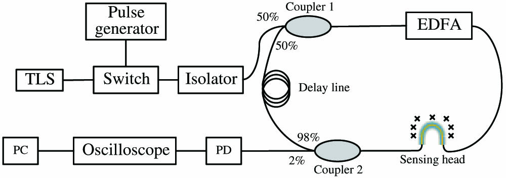
    Fig. 1. Schematic diagram of the sensing system.
    Schematic of the sensing head based on an MF-coated U-bent fiber structure.
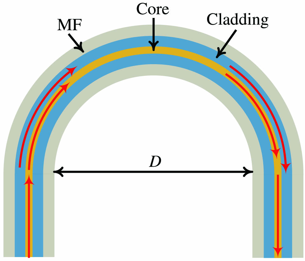
    Fig. 2. Schematic of the sensing head based on an MF-coated U-bent fiber structure.
    Schematic diagrams for measuring (a) the gain characteristic of the EDFA module depending on wavelength and (b) the transmission spectrum of the sensing head in the MF under 0 Oe. OPM, optical powermeter; BBS, broadband source (Lightcomm Tecnologia Ltd.); OSA, optical spectrum analyzer (Advantest Q8384).
    Fig. 3. Schematic diagrams for measuring (a) the gain characteristic of the EDFA module depending on wavelength and (b) the transmission spectrum of the sensing head in the MF under 0 Oe. OPM, optical powermeter; BBS, broadband source (Lightcomm Tecnologia Ltd.); OSA, optical spectrum analyzer (Advantest Q8384).
    Measured transmittance spectrum of the sensing head and the gain characteristic curve of the EDFA module.
    Fig. 4. Measured transmittance spectrum of the sensing head and the gain characteristic curve of the EDFA module.
    (a) Spectral response of the sensing head to the applied magnetic field. (b) The transmittance change at 1575 nm depending on H.
    Fig. 5. (a) Spectral response of the sensing head to the applied magnetic field. (b) The transmittance change at 1575 nm depending on H.
    Output decay trains and the corresponding exponent fittings of the peaks under H of (a) 0 and (b) 250 Oe.
    Fig. 6. Output decay trains and the corresponding exponent fittings of the peaks under H of (a) 0 and (b) 250 Oe.
    Measured ring-down time depending on H. Inset: the statistics and fitting results.
    Fig. 7. Measured ring-down time depending on H. Inset: the statistics and fitting results.
    λ (nm)155515601565157015751580
    Gnor0.900.950.981.000.980.94
    V (dB)10.419.047.135.875.495.78
    N127>35>3514
    Q0.490.590.770.961.000.91
    Table 1. Values of Gnor, V, N, and Q at Different Wavelengths
    Yaofei Chen, Tiegen Liu, Qun Han, Wenchuan Yan, Lin Yu. Fiber loop ring-down cavity integrated U-bent single-mode-fiber for magnetic field sensing[J]. Photonics Research, 2016, 4(6): 322
    Download Citation