• Photonics Research
  • Vol. 9, Issue 5, 893 (2021)
Renduo Qi1, Qiancheng Xu1, Ning Wu1, Kaiyu Cui1、2、3, Wei Zhang1、2、3、*, and Yidong Huang1、2、3
Author Affiliations
  • 1Beijing National Research Center for Information Science and Technology (BNRist), Beijing Innovation Center for Future Chips, Electronic Engineering Department, Tsinghua University, Beijing 100084, China
  • 2Frontier Science Center for Quantum Information, Beijing 100084, China
  • 3Beijing Academy of Quantum Information Sciences, Beijing 100193, China
  • show less
    DOI: 10.1364/PRJ.417933 Cite this Article Set citation alerts
    Renduo Qi, Qiancheng Xu, Ning Wu, Kaiyu Cui, Wei Zhang, Yidong Huang. Nonsuspended optomechanical crystal cavities using As2S3 chalcogenide glass[J]. Photonics Research, 2021, 9(5): 893 Copy Citation Text show less
    (a) The top view schematic of the nonsuspended As2S3 optomechanical crystal cavity. (b) A unit cell of the optomechanical crystal in the mirror region.
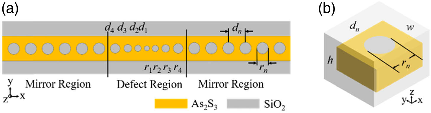
    Fig. 1. (a) The top view schematic of the nonsuspended As2S3 optomechanical crystal cavity. (b) A unit cell of the optomechanical crystal in the mirror region.
    (a) Optical band structure of the unit cell in the mirror region. (b) Acoustic band structure of the unit cell in the mirror region. (c) Electric field component Ey of the optical defect mode at the X point. Left: distribution of Ey at plane x=d1/2. Right: distribution of Ey at plane z=0. [The coordinate of the cavity center is set as (0,0,0).] (d) Displacement field component ux of the acoustic defect mode at the X point. Left: distribution of ux at plane x=d1/2. Right: distribution of ux at plane z=0.
    Fig. 2. (a) Optical band structure of the unit cell in the mirror region. (b) Acoustic band structure of the unit cell in the mirror region. (c) Electric field component Ey of the optical defect mode at the X point. Left: distribution of Ey at plane x=d1/2. Right: distribution of Ey at plane z=0. [The coordinate of the cavity center is set as (0,0,0).] (d) Displacement field component ux of the acoustic defect mode at the X point. Left: distribution of ux at plane x=d1/2. Right: distribution of ux at plane z=0.
    (a) Displacement field profile (ux) of a confined acoustic Bloch mode at the Γ point. (b) 2D FT spectrum of ux of the acoustic Bloch mode at the cavity interface perpendicular to the z direction (left) and interface perpendicular to the y direction (right). (c) Electric field profile (Ey) of a confined optical Bloch mode at the Γ point. (d) 2D FT spectrum of Ey of the optical Bloch mode at the cavity interface perpendicular to the z direction (left) and interface perpendicular to the y direction (right). (e) Electric field component Ey of the optical defect mode at the Γ point. Left: distribution of Ey at plane x=d1/4. Right: distribution of Ey at plane z=0. (f) Displacement field component ux of the acoustic defect mode at the Γ point. Left: distribution of ux at plane x=d1/4. Right: distribution of ux at plane z=0. (g) 2D FT spectrum of Ey of the optical defect mode at the cavity interface perpendicular to the y direction (left). 2D FT spectrum of ux of the acoustic defect mode at the cavity interface perpendicular to the y direction (right).
    Fig. 3. (a) Displacement field profile (ux) of a confined acoustic Bloch mode at the Γ point. (b) 2D FT spectrum of ux of the acoustic Bloch mode at the cavity interface perpendicular to the z direction (left) and interface perpendicular to the y direction (right). (c) Electric field profile (Ey) of a confined optical Bloch mode at the Γ point. (d) 2D FT spectrum of Ey of the optical Bloch mode at the cavity interface perpendicular to the z direction (left) and interface perpendicular to the y direction (right). (e) Electric field component Ey of the optical defect mode at the Γ point. Left: distribution of Ey at plane x=d1/4. Right: distribution of Ey at plane z=0. (f) Displacement field component ux of the acoustic defect mode at the Γ point. Left: distribution of ux at plane x=d1/4. Right: distribution of ux at plane z=0. (g) 2D FT spectrum of Ey of the optical defect mode at the cavity interface perpendicular to the y direction (left). 2D FT spectrum of ux of the acoustic defect mode at the cavity interface perpendicular to the y direction (right).
    (a) A dual-cavity system of nonsuspended As2S3 optomechanical crystal cavities with a separation distance L. (b) Profiles of the calculated supermodes in the dual-cavity system. Top: the odd mode. Bottom: the even mode. (c) Left ordinate: calculated acoustic coupling rates between two identical cavities (black solid line) and between two different cavities with the same acoustic frequency (black dashed line). Right ordinate: optical coupling rates between two identical cavities (red solid line) and between two different cavities with the same acoustic frequency (red dashed line).
    Fig. 4. (a) A dual-cavity system of nonsuspended As2S3 optomechanical crystal cavities with a separation distance L. (b) Profiles of the calculated supermodes in the dual-cavity system. Top: the odd mode. Bottom: the even mode. (c) Left ordinate: calculated acoustic coupling rates between two identical cavities (black solid line) and between two different cavities with the same acoustic frequency (black dashed line). Right ordinate: optical coupling rates between two identical cavities (red solid line) and between two different cavities with the same acoustic frequency (red dashed line).
    ParameterModes at the X pointModes at the Γ point
    r185 nm113 nm
    rn147 nm135 nm
    d1416 nm811 nm
    dn466 nm830 nm
    w557 nm609 nm
    t374 nm400 nm
    Table 1. Structural Parameters of the Cavity
    Renduo Qi, Qiancheng Xu, Ning Wu, Kaiyu Cui, Wei Zhang, Yidong Huang. Nonsuspended optomechanical crystal cavities using As2S3 chalcogenide glass[J]. Photonics Research, 2021, 9(5): 893
    Download Citation