
Renduo Qi, Qiancheng Xu, Ning Wu, Kaiyu Cui, Wei Zhang, Yidong Huang. Nonsuspended optomechanical crystal cavities using As2S3 chalcogenide glass[J]. Photonics Research, 2021, 9(5): 893
- Photonics Research
- Vol. 9, Issue 5, 893 (2021)
Abstract
1. INTRODUCTION
Cavity optomechanics explores the interaction between optical and mechanical modes in optical/mechanical resonance systems, and it is promising for a wide range of applications such as high-precision sensing [1–3], laser cooling [4], and nonreciprocal devices [5,6]. Various microcavity systems have been investigated for cavity optomechanics, including microtoroids [7], microdisks [8], and optomechanical crystal cavities [9–13]. Among these systems, optomechanical crystal cavities have attracted much attention because of their smaller mode volumes and higher optomechanical coupling rates [14,15]. So far, silicon is the dominant material for optomechanical crystal cavities, which are usually fabricated on silicon-on-insulator (SOI) substrates. However, since the sound velocity in silicon is larger than that in silica, it is hard to confine acoustic modes in the silicon layers [16]. Therefore, suspended cavity structures are required in these systems to confine the acoustic modes and enhance the overlap between optical and acoustic modes. However, the suspended structures would increase the difficulty of fabrication and limit the structural complexity of the devices. In addition, extra structure designs are required in the suspended cavity systems to realize further functions such as acoustic mode coupling [17,18].
Recently, chalcogenide glasses (ChGs) have drawn a lot of interest in nonlinear optics because of their large Kerr nonlinearity as well as low two-photon absorption [19,20]. More importantly, these materials have relatively high refractive index and low sound velocity, so that both optical modes and acoustic modes can be confined in the ChG core without using suspended structures [21]. Based on this feature, different integrated ChG devices have been fabricated for applications such as stimulated Brillouin scattering [22–24], which also results from the interaction between photons and phonons in traveling acoustic modes. Therefore, it could be expected to achieve effective optomechanical coupling based on nonsuspended ChG devices. The nonsuspended structures have the advantage of more flexible designs, and they can directly realize functions such as acoustic mode coupling among cavity arrays and external modulations without extra structures.
In this work, a nonsuspended optomechanical crystal cavity using material with nanobeam structure is proposed. Theoretical analysis shows that both optical and acoustic modes are well confined in the cavity by adjusting and optimizing the structural parameters. Two different types of optical and acoustic defect modes are calculated, and an optomechanical coupling rate of 82.3 kHz is obtained. The coupling of acoustic modes between two nonsuspended optomechanical crystal cavities is also demonstrated, showing that the proposed cavity structure has great potential in realizing complex optomechanical functions.
Sign up for Photonics Research TOC. Get the latest issue of Photonics Research delivered right to you!Sign up now
2. CAVITY STRUCTURE AND MODE ANALYSIS
A. Cavity Design
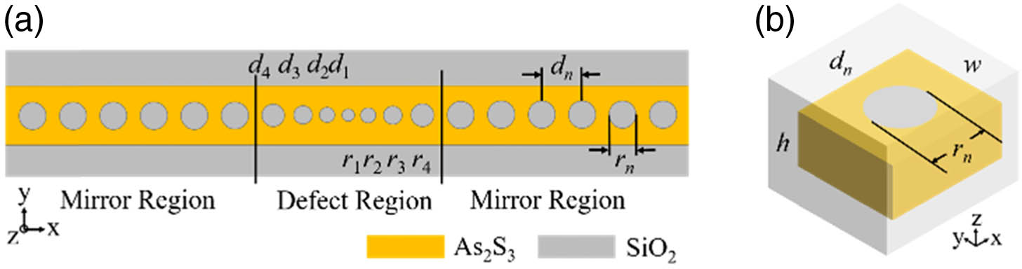
Figure 1.(a) The top view schematic of the nonsuspended
B. Optical and Acoustic Defect Modes at the X Point
![]()
Figure 2.(a) Optical band structure of the unit cell in the mirror region. (b) Acoustic band structure of the unit cell in the mirror region. (c) Electric field component
The acoustic band of the periodic structure is then calculated using FEM. In the calculation, the unit cell is set with Bloch boundary condition in the direction. The density, Young’s modulus, and Poisson’s ratio of and silica are set to be , 16 GPa, 0.24 and , 73.1 GPa, 0.17, respectively [16,26]. Figure 2(b) shows the calculated acoustic bands of - and -symmetric modes using the structural parameters mentioned above. In the nonsuspended cavity, acoustic defect modes may couple with the acoustic waves in the surrounding material, leading to field leakage. The blue line and purple line in Fig. 2(b) indicate the dispersion lines of transverse waves and longitudinal waves in silica, respectively. The acoustic modes below both of the lines are guided modes, and an acoustic band gap is generated between 3.42 and 3.73 GHz. Figure 2(d) shows the displacement field component of the acoustic defect mode. The component is chosen for plotting since it has the most overlap with the electric field, resulting in a dominant contribution to the optomechanical coupling rate. The frequency of the mode is 3.67 GHz, which is indicated by the red dashed line in the acoustic band diagram. The calculated Q factor of the mode with 20 periods of optomechanical crystals in the mirror region is 1000. It is worth noting that the Q factors of the investigated acoustic mode under different numbers of periods are also calculated. Results show that when the number of periods is relatively small, the Q factor rises with increasing number of periods, and the overall loss is mainly composed of losses through the mirror regions. Then the Q factor stops increasing and remains almost unchanged after the number of periods reaches 20. It indicates that the vertical losses into the surrounding cladding start to dominate when the number of periods is over 20.
The optomechanical coupling rate describes the interaction strength between optical and mechanical modes. It is defined as the optical frequency shift induced by the zero-point displacement of the mechanical mode and can be expressed by the following equation [27]:
To optimize the cavity design, an algorithm based on simulated annealing is used to achieve the maximum optomechanical coupling rate. The six independent geometric parameters for optimization are (, , , , , ), and the optimized results are shown in the second column of Table 1. The optomechanical coupling rate of the cavity is calculated to be , composed of from the moving boundary effect and 3.1 kHz from the photoelastic effect. The obtained coupling rate is relatively low compared to the coupling rate of suspended nanobeam cavities. It is due to the canceling of the optomechanical coupling rate contribution from two adjacent unit cells. Taking the photoelastic effect for example, the coupling rate caused by the photoelastic effect is proportional to the integral of the strain field of the acoustic mode and the square of the electric field of the optical mode. For the modes at the X point of the band diagram, the electric field and strain field in two adjacent unit cells have the opposite phase. Therefore, the contributions of coupling rate from two adjacent unit cells have different signs and cancel each other out, resulting in a relatively low coupling rate of the whole structure.
C. Optical and Acoustic Defect Modes at the Γ Point
![]()
Figure 3.(a) Displacement field profile (
Through appropriate design of the cavity structure, the optical and acoustic defect modes at the point can be supported by the cavity. Figures 3(e)–3(f) are the calculated optical and acoustic defect mode profiles. The frequency and calculated Q factor of the optical and acoustic modes are 196.8 THz, 3000 and 3.44 GHz, 500, respectively, with 20 periods of unit cells in each mirror region. We also calculate the Q factors of the acoustic mode at the point under different numbers of periods in the mirror regions. It shows that the Q factor stops increasing and remains almost unchanged with the number of periods when it is over 20, like the case of the acoustic mode at the X point. The FT spectra of the defect optical and acoustic modes at the cavity interfaces are shown in Fig. 3(g). The optomechanical coupling rate between these two modes is calculated to be 82.3 kHz, which is much higher than the coupling rate of the cavity supporting optical and acoustic modes at the X point. Simulation results show that the coupling rate between these two modes at the point is also dominated by the contribution of .
3. INTERCAVITY ACOUSTIC MODE COUPLING
![]()
Figure 4.(a) A dual-cavity system of nonsuspended
In some applications, the optical coupling between cavities is not expected while acoustic coupling is required. It can be realized by tuning the optical frequency of one cavity while keeping the acoustic frequency unchanged, so that optical coupling could not occur due to the inconsistent optical frequencies of the two cavities. A possible way to realize this is to adjust the radii of silica holes and lattice constants in the defect region of one cavity. The black dashed line in Fig. 4(c) shows the calculated acoustic coupling rates between two nonsuspended optomechanical crystal cavities with different structural parameters. These two cavities have the same acoustic frequency, while the optical frequencies are 193 THz and 197 THz, respectively. The result shows that acoustic mode coupling also occurs on this condition. The optical coupling rates between two cavities are also calculated and plotted in Fig. 4(c). The red solid line indicates the optical coupling rate between two identical cavities, and the red dashed line is the coupling rate between cavities with different optical frequencies. It can be seen that optical mode coupling could be suppressed by this way, while the acoustic mode coupling condition remains almost unchanged.
4. CONCLUSION
In this paper, we have proposed a nonsuspended optomechanical crystal cavity. The core of the cavity is an nanobeam structure, and the whole cavity is surrounded by silica cladding. Different optical and acoustic defect modes are supported in the cavity with proper structural design. Optical and acoustic modes at the X point and point of the band diagram are analyzed. The designed acoustic mode at the point has a frequency of 3.44 GHz, and an optomechanical coupling rate of 82.3 kHz is obtained. The Q factors of the modes and the coupling rates could be improved by further optimization of the cavity design. In addition, acoustic mode coupling between two nonsuspended optomechanical crystal cavities is realized directly without extra structures. The calculation results show that the proposed nonsuspended cavities have great potential for realizing further optomechanical applications in multicavity systems.
References
[1] A. G. Krause, M. Winger, T. D. Blasius, Q. Lin, O. Painter. A high-resolution microchip optomechanical accelerometer. Nat. Photonics, 6, 768-772(2012).
[2] E. Gavartin, P. Verlot, T. J. Kippenberg. A hybrid on-chip optomechanical transducer for ultrasensitive force measurements. Nat. Nanotechnol., 7, 509-514(2012).
[3] Y. Chen, W. S. Fegadolli, W. M. Jones, A. Scherer, M. Li. Ultrasensitive gas-phase chemical sensing based on functionalized photonic crystal nanobeam cavities. ACS Nano, 8, 522-527(2014).
[4] Y. C. Liu, Y. F. Xiao, X. Luan, C. W. Wong. Dynamic dissipative cooling of a mechanical resonator in strong coupling optomechanics. Phys. Rev. Lett., 110, 153606(2013).
[5] S. Manipatruni, J. T. Robinson, M. Lipson. Optical nonreciprocity in optomechanical structures. Phys. Rev. Lett., 102, 213903(2009).
[6] F. Ruesink, M. A. Miri, A. Alù, E. Verhagen. Nonreciprocity and magnetic-free isolation based on optomechanical interactions. Nat. Commun., 7, 13662(2016).
[7] M. Hossein-Zadeh, K. J. Vahala. Observation of optical spring effect in a microtoroidal optomechanical resonator. Opt. Lett., 32, 1611-1613(2007).
[8] X. Sun, X. Zhang, H. X. Tang. High-
[9] M. Eichenfield, J. Chan, R. M. Camacho, K. J. Vahala, O. Painter. Optomechanical crystals. Nature, 462, 78-82(2009).
[10] J. Gomis-Bresco, D. Navarro-Urrios, M. Oudich, S. El-Jallal, A. Griol, D. Puerto, E. Chavez, Y. Pennec, B. Djafari-Rouhani, F. Alzina, A. Martínez, C. M. S. Torres. A one-dimensional optomechanical crystal with a complete phononic band gap. Nat. Commun., 5, 4452(2014).
[11] X. Zhang, G. Zhou, P. Shi, H. Du, T. Lin, J. Teng, F. S. Chau. On-chip integrated optofluidic complex refractive index sensing using silicon photonic crystal nanobeam cavities. Opt. Lett., 41, 1197-1200(2016).
[12] S. C. Wu, L. G. Qin, J. Jing, T. M. Yan, J. Lu, Z. Y. Wang. Microwave-controlled optical double optomechanically induced transparency in a hybrid piezo-optomechanical cavity system. Phys. Rev. A, 98, 013807(2018).
[13] W. Jiang, R. N. Patel, F. M. Mayor, T. P. McKenna, P. Arrangoiz-Arriola, C. J. Sarabalis, J. D. Witmer, R. V. A. N. Laer, A. H. Safavi-Naeini. Lithium niobate piezo-optomechanical crystals. Optica, 6, 845-853(2019).
[14] J. Chan, A. H. Safavi-Naeini, J. T. Hill, S. Meenehan, O. Painter. Optimized optomechanical crystal cavity with acoustic radiation shield. Appl. Phys. Lett., 101, 081115(2012).
[15] Y. Li, K. Cui, X. Feng, Y. Huang, Z. Huang, F. Liu, W. Zhang. Optomechanical crystal nanobeam cavity with high optomechanical coupling rate. J. Opt., 17, 045001(2015).
[16] C. J. Sarabalis, J. T. Hill, A. H. Safavi-Naeini. Guided acoustic and optical waves in silicon-on-insulator for Brillouin scattering and optomechanics. APL Photon., 1, 071301(2016).
[17] Z. Feng, J. Ma, X. Sun. Parity–time-symmetric mechanical systems by the cavity optomechanical effect. Opt. Lett., 43, 4088-4091(2018).
[18] K. Fang, M. H. Matheny, X. Luan, O. Painter. Optical transduction and routing of microwave phonons in cavity-optomechanical circuits. Nat. Photonics, 10, 489-496(2016).
[19] B. J. Eggleton, B. Luther-Davies, K. Richardson. Chalcogenide photonics. Nat. Photonics, 5, 141-148(2011).
[20] T. Wang, X. Gai, W. Wei, R. Wang, Z. Yang, X. Shen, S. Madden, B. Luther-Davies. Systematic z-scan measurements of the third order nonlinearity of chalcogenide glasses. Opt. Mater. Express, 4, 1011-1022(2014).
[21] C. G. Poulton, R. Pant, B. J. Eggleton. Acoustic confinement and stimulated Brillouin scattering in integrated optical waveguides. J. Opt. Soc. Am. B, 30, 2657-2664(2013).
[22] R. Pant, C. G. Poulton, D.-Y. Choi, H. Mcfarlane, S. Hile, E. Li, L. Thevenaz, B. Luther-Davies, S. J. Madden, B. J. Eggleton. On-chip stimulated Brillouin scattering. Opt. Express, 19, 8285-8290(2011).
[23] M. Merklein, I. V. Kabakova, T. F. S. Büttner, D. Y. Choi, B. Luther-Davies, S. J. Madden, B. J. Eggleton. Enhancing and inhibiting stimulated Brillouin scattering in photonic integrated circuits. Nat. Commun., 6, 6396(2015).
[24] B. J. Eggleton, C. G. Poulton, R. Pant. Inducing and harnessing stimulated Brillouin scattering in photonic integrated circuits. Adv. Opt. Photon., 5, 536-587(2013).
[25] C. Li, P. Guo, W. Huang, W. Zhang, P. Xu, P. Zhang. Reverse-strip-structure Ge28Sb12Se60 chalcogenide glass waveguides prepared by micro-trench filling and lift-off. J. Opt. Soc. Am. B, 37, 82-87(2020).
[26] J. S. Sanghera, L. B. Shaw, I. D. Aggarwal. Applications of chalcogenide glass optical fibers. C. R. Chim., 5, 873-883(2002).
[27] M. Aspelmeyer, T. J. Kippenberg, F. Marquardt. Cavity optomechanics. Rev. Mod. Phys., 86, 1391-1452(2014).
[28] S. G. Johnson, M. Ibanescu, M. A. Skorobogatiy, O. Weisberg, J. D. Joannopoulos, Y. Fink. Perturbation theory for Maxwell’s equations with shifting material boundaries. Phys. Rev. E, 65, 066611(2002).
[29] D. K. Biegelsen. Photoelastic tensor of silicon and the volume dependence of the average gap. Phys. Rev. Lett., 32, 1196-1199(1974).
[30] A. H. Safavi-Naeini, O. Painter. Design of optomechanical cavities and waveguides on a simultaneous bandgap phononic-photonic crystal slab. Opt. Express, 18, 14926-14943(2010).
[31] R. W. Dixon. Photoelastic properties of selected materials and their relevance for applications to acoustic light modulators and scanners. J. Appl. Phys., 38, 5149-5153(1967).
[32] Y. Akahane, T. Asano, B. S. Song, S. Noda. High-
[33] T. Xu, M. S. Wheeler, S. V. Nair, H. E. Ruda, M. Mojahedi, J. S. Aitchison. Highly confined mode above the light line in a two-dimensional photonic crystal slab. Appl. Phys. Lett., 93, 241105(2008).
[34] T. Huan, R. Zhou, H. Ian. Dynamic entanglement transfer in a double-cavity optomechanical system. Phys. Rev. A, 92, 022301(2015).
[35] U. S. Sainadh, A. Narayanan. Mechanical switch for state transfer in dual-cavity optomechanical systems. Phys. Rev. A, 88, 033802(2013).

Set citation alerts for the article
Please enter your email address
© Copyright 2018-2021 | Chinese Laser Press. All Rights Reserved 沪ICP备15018463号-20