• Advanced Photonics
  • Vol. 3, Issue 2, 026001 (2021)
Xiao Tian Yan1、†, Wenxuan Tang1、2、*, Jun Feng Liu1, Meng Wang1, Xin Xin Gao1, and Tie Jun Cui1、2、*
Author Affiliations
  • 1Southeast University, School of Information Science and Engineering, State Key Laboratory of Millimeter Waves, Nanjing, China
  • 2Southeast University, Institute of Electromagnetic Space, Nanjing, China
  • show less
    DOI: 10.1117/1.AP.3.2.026001 Cite this Article Set citation alerts
    Xiao Tian Yan, Wenxuan Tang, Jun Feng Liu, Meng Wang, Xin Xin Gao, Tie Jun Cui. Glide symmetry for mode control and significant suppression of coupling in dual-strip SSPP transmission lines[J]. Advanced Photonics, 2021, 3(2): 026001 Copy Citation Text show less
    (a) A nonglide unit cell in the dual-strip SSPP TL. The line width, period, width, and depth of the slots are h=6 mm, p=3.6 mm, a=0.8 mm, and d=5.2 mm, respectively. In this work, the thickness of the two metal layers is t=0.018 mm, and the substrate has a relative permittivity of 3.48 with thickness of tsub=0.762 mm and width of wsub=30 mm. (b) A glide symmetric unit cell. The centers of the slots in the upper and lower layers are misaligned with a glide distance of gl=0.5p along the x axis. (c) The glide symmetric dual-strip SSPP TL. Section I is the MS line at the input and output, and the widths of the upper and lower strips are w0=1.7 mm and wgnd=25 mm, respectively. Section II is the transition section and Section III is composed of uniform glide symmetric unit cells.
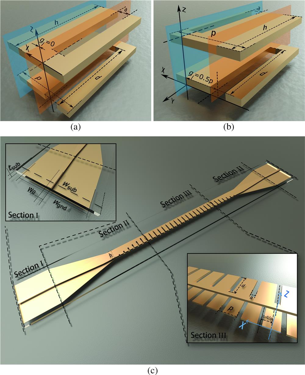
    Fig. 1. (a) A nonglide unit cell in the dual-strip SSPP TL. The line width, period, width, and depth of the slots are h=6  mm, p=3.6  mm, a=0.8  mm, and d=5.2  mm, respectively. In this work, the thickness of the two metal layers is t=0.018  mm, and the substrate has a relative permittivity of 3.48 with thickness of tsub=0.762  mm and width of wsub=30  mm. (b) A glide symmetric unit cell. The centers of the slots in the upper and lower layers are misaligned with a glide distance of gl=0.5p along the x axis. (c) The glide symmetric dual-strip SSPP TL. Section I is the MS line at the input and output, and the widths of the upper and lower strips are w0=1.7  mm and wgnd=25  mm, respectively. Section II is the transition section and Section III is composed of uniform glide symmetric unit cells.
    Dispersion diagram of the nonglide and glide symmetric unit cells.
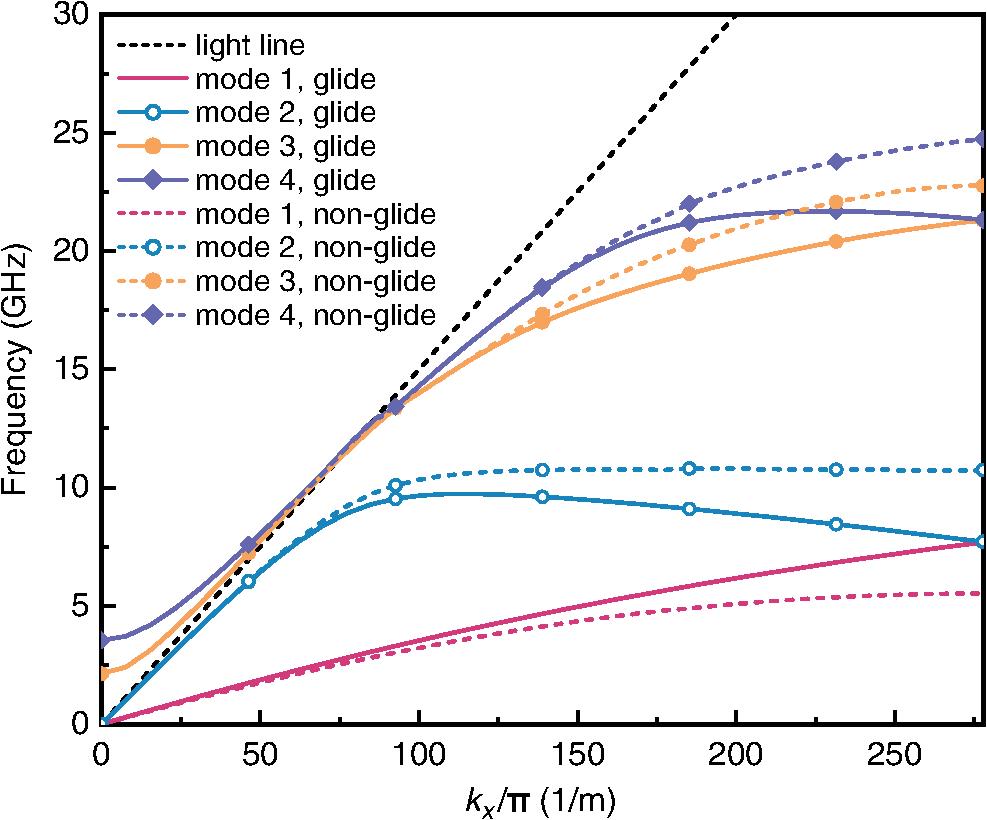
    Fig. 2. Dispersion diagram of the nonglide and glide symmetric unit cells.
    (Side view) (a), (b) Distributions of the electric fields of the nonglide symmetric structure at the orange and the blue cross sections indicated in Fig. 1(a), respectively. (c), (d) Distributions of the electric fields of the glide symmetric structure at the orange and the blue cross sections indicated in Fig. 1(b), respectively.
    Fig. 3. (Side view) (a), (b) Distributions of the electric fields of the nonglide symmetric structure at the orange and the blue cross sections indicated in Fig. 1(a), respectively. (c), (d) Distributions of the electric fields of the glide symmetric structure at the orange and the blue cross sections indicated in Fig. 1(b), respectively.
    Measured reflection coefficients (S11) and transmission coefficients (S21).
    Fig. 4. Measured reflection coefficients (S11) and transmission coefficients (S21).
    Magnitude distributions of the near electric field for (a) the nonglide symmetric and (b) the glide symmetric SSPP TLs at different frequencies.
    Fig. 5. Magnitude distributions of the near electric field for (a) the nonglide symmetric and (b) the glide symmetric SSPP TLs at different frequencies.
    The four-port model composed of two channels; one is the nonglide symmetric TL channel, and the other is the glide symmetric one.
    Fig. 6. The four-port model composed of two channels; one is the nonglide symmetric TL channel, and the other is the glide symmetric one.
    Simulated isolation coefficients (S41 and S14) and coupling coefficients (S31 and S24) of the two SSPP TLs.
    Fig. 7. Simulated isolation coefficients (S41 and S14) and coupling coefficients (S31 and S24) of the two SSPP TLs.
    The normalized and average mode coupling coefficients in two types of TL arrays at different line separations (dis=0.6 mm and dis=2 mm).
    Fig. 8. The normalized and average mode coupling coefficients in two types of TL arrays at different line separations (dis=0.6  mm and dis=2  mm).
    Comparison of the reflection coefficient (S11), transmission coefficient (S21), coupling coefficient (S31), and isolation coefficient (S41) for the hybrid TL array (composed of a glide symmetric TL and a nonglide symmetric TL) and the uniform TL arrays (composed of two nonglide symmetric TLs and two glide symmetric TLs, respectively).
    Fig. 9. Comparison of the reflection coefficient (S11), transmission coefficient (S21), coupling coefficient (S31), and isolation coefficient (S41) for the hybrid TL array (composed of a glide symmetric TL and a nonglide symmetric TL) and the uniform TL arrays (composed of two nonglide symmetric TLs and two glide symmetric TLs, respectively).
    Distributions of the near-electric field of the hybrid TL array and the uniform TL array with line separations being 0.6 and 2 mm at 2 and 5 GHz, respectively.
    Fig. 10. Distributions of the near-electric field of the hybrid TL array and the uniform TL array with line separations being 0.6 and 2 mm at 2 and 5 GHz, respectively.
    Xiao Tian Yan, Wenxuan Tang, Jun Feng Liu, Meng Wang, Xin Xin Gao, Tie Jun Cui. Glide symmetry for mode control and significant suppression of coupling in dual-strip SSPP transmission lines[J]. Advanced Photonics, 2021, 3(2): 026001
    Download Citation