1Tianjin Key Laboratory of Integrated Design and On-line Monitoring for Light Industry & Food Machinery and Equipment, College of Mechanical Engineering, Tianjin University of Science and Technology, Tianjin 300222, China
2Centre of MicroNano Manufacturing Technology, Tianjin University, Tianjin 300072, China
3Tianjin Sino-German University of Applied Sciences, Tianjin 300350, China
Ying Cheng, Zechao Wang, Xiaobing Xie, Yongbin Lu, Wenshuang Chang. Design and fabrication of a Fresnel lens for laser lamps[J]. Infrared and Laser Engineering, 2020, 49(3): 0314003
Copy Citation Text
Compared with LED lamp, laser lamp has the advantages of small energy consumption, small volume and high brightness. It will become a new trend of vehicle lamp. A design method of laser lamp is proposed. The light source is laser diode, which is converted into white light by phosphors film. The optical test platform is built to study the optical characteristics of the source, and the machine vision method is used to study the change of the shape and size of the light spot before and after the phosphors, which provides a theoretical basis for subsequent optical design. Fresnel lens is designed by non-imaging optical design method to achieve laser convergence and shaping. The Fresnel lens is machined using ultra-precision turning. The laser lamp prototype is assembled and tested, and the feasibility of the design method is verified by optical simulation and optical experiment.
The development of automobile headlamp has experienced the development of incandescent lamp, halogen lamp, xenon headlamp and LED[1], and new types of light sources have appeared gradually, such as laser. Compared with LED, Laser Diode (LD) has the advantages of large output power, small volume, fast response, long life and high energy efficiency. And laser lamp has the advantages of small divergence angle, long irradiation range, low power requirement and high brightness compared with LED headlamp.
In 2013, BMW launched a laser headlamp for automobiles, which consists of a semiconductor laser, a phosphor, and mirrors. The laser is a blue-light semiconductor laser. Three laser beams converge into a packaged tank with phosphor through three mirrors, and the phosphor emits long-wavelength light. Then blue laser and long-wavelength light mix together into white light. The white light is reflected through the light distribution mirror and directed to the road ahead[2].
Automobile illumination system belongs to the field of non-imaging optics, which needs high energy efficiency and illumination uniformity. At present, a lot of researches have been done on LED lamp[3-6]. Freeform mirror or lens can be used in the optical system of LED lamp[7]. The freeform surface design of LED automotive headlights can be realized by commercial software for optical design[8]. In addition, non-imaging optical freeform surface design method can also be used, such as feedback function[9], source-target maps[10], surface construction method[11], and so on.
Non-imaging optical design can be carried out only under the known characteristics of the light source. Such as for the LED lamp design, the light distribution curve, luminous intensity, spectral distribution of the LED light source must be known. Blue laser diodes are often used to excite the yellow phosphor, which can generate white light for automobile headlamps. But there are few studies on the characteristics of laser-driven white source[12]. The right laser source model is the basis for optical design and simulation.
The laser lamps designed in this paper are used for off-road vehicles, engineering vehicles, emergency vehicle, etc., which need to be used for night or long-distance inspections, construction lighting and other lighting needs in workplaces such as night work or in the wilderness. The spotlights are mounted on the top of the automobiles. Compared with traditional lens, Fresnel lens has the advantages of light weight and small volume.
In this paper, a method for detecting the characteristics of laser-driven white source is proposed. An optical model of the laser-driven white source is established to design the laser lamp. The lamp uses Fresnel lens to achieve converging and shaping of laser. According to the characteristics of laser-driven white source, this paper completes the optical design and processing of Fresnel lens, system assembling, testing of the laser lamp prototype.
1 Design method
1.1 Test and analysis of light source
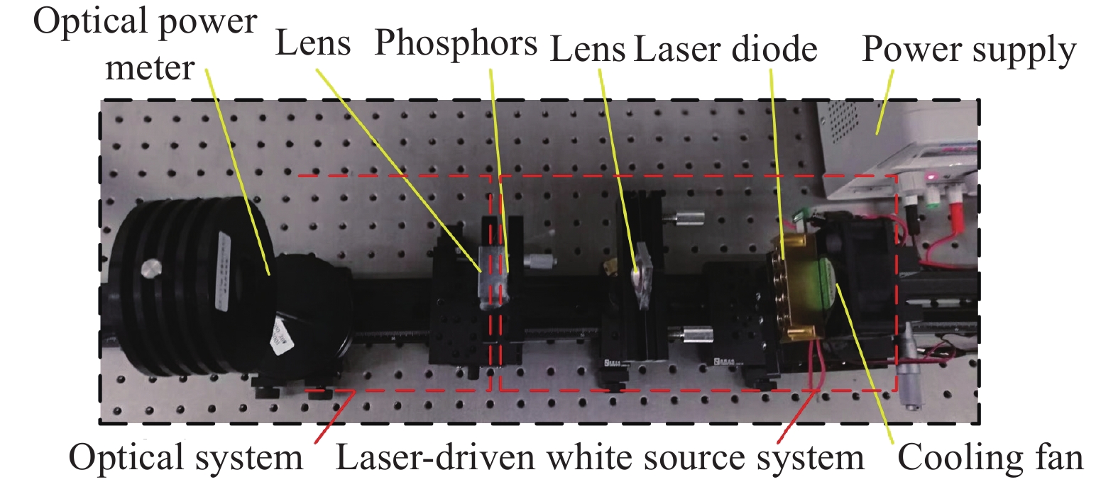
The laser source uses a 450 nm laser diode. The light emitted from the laser diode is concentrated by the first lens, then incidents to the phosphor. The light emits after absorption, scattering and refraction of phosphor. Therefore, the laser lamp consists of two parts: laser-driven white source system and optical system. The phosphor is the bridge between these two parts. For the optical design and simulation, it is necessary to test the characteristics of the light source and build a test platform, which studies the light efficiency of laser source, the distribution of spot energy and so on.
Firstly, the power conversion efficiency of laser-driven white source is tested, and the test platform is shown in Fig.1. Using this detection method, the luminous flux and illumination after passing through the phosphors is measured by different detection probes.
The power conversion efficiency is the ratio of optical power to the electric power. Using optical power probe, the light power is measured with different excitation electric powers, and the power conversion efficiency of the source is 26%, as shown in Fig.2.
Because of the complexity of phosphor luminescence mechanism, it is difficult to accurately establish simulation model in optical simulation software. In this paper, the machine vision method is used to study the change of the shape and size of the light spot before and after the phosphors, which provides a theoretical basis for subsequent optical design. As shown in Fig.3, a CCD is placed behind the phosphor to obtain the laser spot. After testing, it can be found that the shape of the two spots remain unchanged before and after the phosphor, but the size of the spot emitted by the phosphor is slightly larger than that of the incident on the phosphor. Three kinds of spherical lenses are used to converge the laser light, which found that a large F-number, large refractive index lens has a smaller spot size incident on the phosphor and the shape is closer to a square, as shown in Fig.4. Therefore, the first lens is chosen as the converging lens. The edge length of the square spot incident on the phosphor is about 2.30 mm, and the edge length of the square spot emitted from the phosphor is 2.68 mm. After the above analysis, the optical system design can regard the source as Lambertian source with the size of 3 mm × 3 mm.
Fresnel lenses are commonly used in concentrated photovoltaic (CPV) systems to collect solar light[13]. In this paper, Fresnel lens is used in laser lamp system, which is the reverse of the concentrator design.
The optical structure of the laser lamp is shown in Fig.5. The blue laser emitted by the four-core laser diode converges through the first lens, and is become white light by the phosphor. Then it passes through the second lens and the Fresnel lens successively. Both the lenses are aspherical lenses.
Figure 5.Schematic diagram of laser light structure
The design requirement is that the diameter of the spot is less than 3 m at a distance of 25 m from the light source, and the irradiance of the receiving is not less than 150 lx.
Two approximations are made to the computational model: the light source is a point source and the exit light is collimated.
The design of Fresnel lens is based on two dimension geometric construction method (2DGCM)[14]. The principle of the design method of Fresnel lens is shown in Fig.6. Cartesian coordinate system is established with point source as coordinate origin and lens optical axis as Z axis. The light from the point source converges through the first lens and then collimates through the Fresnel lens. Because the Fresnel lens is symmetrical about Z axis, it only needs to calculate the surface shape of Fresnel lens in the positive direction of Y axis. The focal length of Fresnel lens is f and the refractive index is n2. The incident plane of Fresnel lens is a plane, which is represented by discrete point Ai,j. The exit surface is an effective working surface, and there are n units in the exit surface. Each unit calculates m sampling points, which is represented by Bi,j. The variable of the prism units is j (1≤j≤n), and the variable of discrete points of each prism unit is i (1≤i≤m). In other words, the point cloud Bi,j on the prism working face is solved on prism unit with edges of Aj and Aj+1.
The whole calculation flow chart is shown in Fig.7. The coordinates of point source O, the maximum angle of light γmax, the refractive index of lens n1 and the focal length f of Fresnel lens are known.
Similarly, the vector v of the exit ray passing through the lens can be determined as shown in Eq. (3), where N1 is the normal vector of the right surface of the lens.
According to the maximum incident angle γmax, the exit light vector v1,1 of the edge light can be obtained, and then according to f, the coordinates of the edge point A1,1 of the Fresnel lens can be obtained.
The calculation flow chart of discrete point Bi,j is shown in Fig.8.
Figure 8.Calculation flow chart of discrete point of Fresnel lens
Firstly, the first prism unit of Fresnel lens is calculated, and the edge points of the incident plane is A1,1. The incident ray v is traveling in a direction difined by unit vector v1,1. The ray v1,1 is refracted from the incident plane of the Fresnel lens and becomes ti,j. The exit ray passes through the working surface of Fresnel lens iswi,j.
The edge point of working face is B1,1, B1,1 = A1,1, t1,1 = v1,1, the normal to the surface is given by unit vector N. Accroding to Snell’ Law, the normal to the surface N1,1 on B1,1 is
Where, p1=n2t and p2=w are the optical momenta of the ray before and after refraction, and
$\left\| {{t}} \right\| = \left\| {{w}} \right\| = 1$.
Then, ray vector ti,j is solved according to Snell's law as shown in Eq. (5), and the second discrete point Bi,j (i=2, j=1) of the first unit is solved according to 2DGCM. The vector of line
$\overline {{B_{i,j}}{B_{i - 1,j}}} $ is perpendicular to the normal vector Ni,j, which satisfies Eq. (6).
Where, N2 is the normal vector of incident plane of Fresnel lens, N2=[−1 0]. Bi,j can be obtained by Eq. (6), and the normal vector Ni,j(j=1) at Bi,j can be obtained by Eq. (4).
According to the same calculation process, the discrete points Bi,j and the normal vector Ni,j of all the working face of Fresnel lens can be obtained. After fitting and rotating the points, the model of the Fresnel lens is obtained, as shown in Fig.9.
Figure 9.Calculation and modeling of discrete points of Fresnel lens
The established model is imported into optical software for ray tracing under the point source, as shown in Fig.10. From the trace results, all light is collimated which agrees with the calculation. The point source is replaced by 3 mm × 3 mm surface source, and two receiving surfaces are established at the distance 40 mm (surface ①) and 25 m from the light source (surface ②) respectively. The illumination distribution on the two receiving surfaces is shown in Fig.11. From the simulation results, the size and uniformity of the spot at 25 m meets the design demand.
The Fresnel lens is machined by ultra-precision single-point diamond lathe[15-16]. The machining process is shown in Fig.12. The material of Fresnel lens is PMMA.
The design surface accuracy of Fresnel lens is less than 50 μm, and its machining accuracy is 5-10 μm. The Fresnel lens can be produced for mass production by injection molding, and the surface accuracy is less than 30 μm, can meet the design requirements.
The prototype of Fresnel lens laser lamp is shown in Fig.13, including Fresnel lens, lamp bracket, laser diode, cooling fan, phosphors film, aspheric lenses. The light source is a four-core laser diode with a wavelength of 450 nm. The supply current of the laser diode is 0.8 A, the excitation electric power of 12.16 W. The output aperture of laser car lamp is 100 mm.
Figure 12.Ultra-precision machining of Fresnel lens
The optical experiment of the prototype is carried out, as shown in Fig.14. The irradiance of the receiving at the distance 25 m from the source is 170 lx, the diameter of light spot is about 1.5 m. The optical experiment results show that the size and uniformity of the spot meet the requirements.
If the application is popularized, aspheric lens is made of glass die-casting and Fresnel lens is made of injection molding. The cost is low and it has a certain competitive advantage over the traditional lamp.
3 Conclusions
In this paper, a design method of laser lamp is proposed. The light source is laser diode, which is converted into white light by phosphors film. The mapping relationship of the spot size between before and after phosphors, which guides the optical design. The laser lamp uses Fresnel lens to shape the beam, and the design method of Fresnel lens is 2DGCM. The correctness of the research process is verified by optical simulation and optical experiment. But the overall size of the design is too large, and the illumination value can be gradually increased, which will be improved in future research.
[2] L Ulrich. BMW laser headlights slice through the dark. IEEE Spectrum, 25, 1-5(2013).
[3] H Wu, X Zhang, P Ge. Double freeform surfaces lens design for LED uniform illumination with high distance–height ratio. Optics & Laser Technology, 73, 166-172(2015).
[8] Jiang J B, Cheung C F, To S, et al. Design fabrication of freefm reflect f automotive headlamp[C]2006 2nd International Conference on Power Electronics Systems Applications, IEEE, 2006: 220224.
[9] H Wu, X Zhang, P Ge. Design method of a light emitting diode front fog lamp based on a freeform reflector. Optics & Laser Technology, 72, 125-133(2015).