• Photonics Research
  • Vol. 9, Issue 12, 2511 (2021)
Yingzhi Li1, Baisong Chen1, Quanxin Na2, Qijie Xie2, Min Tao1, Lanxuan Zhang1, Zihao Zhi1, Yuxuan Li1, Xiaobin Liu1, Xianshu Luo3, Guoqiang Lo3, Fengli Gao1, Xueyan Li1, and Junfeng Song1、2、*
Author Affiliations
  • 1State Key Laboratory on Integrated Optoelectronics, College of Electronic Science and Engineering, Jilin University, Changchun 130012, China
  • 2Peng Cheng Laboratory, Shenzhen 518000, China
  • 3Advance Micro Foundry Pte. Ltd., Singapore 117685, Singapore
  • show less
    DOI: 10.1364/PRJ.437846 Cite this Article Set citation alerts
    Yingzhi Li, Baisong Chen, Quanxin Na, Qijie Xie, Min Tao, Lanxuan Zhang, Zihao Zhi, Yuxuan Li, Xiaobin Liu, Xianshu Luo, Guoqiang Lo, Fengli Gao, Xueyan Li, Junfeng Song. Wide-steering-angle high-resolution optical phased array[J]. Photonics Research, 2021, 9(12): 2511 Copy Citation Text show less

    Abstract

    Optical phased array (OPA) technology is considered a promising solution for solid-state beam steering to supersede the traditional mechanical beam steering. As a key component of the LIDAR system for long-range detection, OPAs featuring a wide steering angle and high resolution without beam aliasing are highly desired. However, a wide steering range requires a waveguide pitch less than half of the wavelength, which is easily subjected to cross talk. Besides, high resolution requires a large aperture, and it is normally achieved by a high count number of waveguides, which complicates the control system. To solve the mentioned issues, we design two high-performance 128-channel OPAs fabricated on a multilayered SiN-on-SOI platform. Attributed to the nonuniform antenna pitch, only 128 waveguides are used to achieve a 4 mm wide aperture. Besides, by virtue of innovative dual-level silicon nitride (Si3N4) waveguide grating antennas, the fishbone antenna OPA achieves a 100°×19.4° field of view (FOV) with divergence of 0.021°×0.029°, and the chain antenna OPA realizes a 140°×19.23° FOV with divergence of 0.021°×0.1°. To our best knowledge, 140° is the widest lateral steering range in two-dimensional OPA, and 0.029° is the smallest longitudinal divergence. Finally, we embed the OPA into a frequency-modulated continuous-wave system to achieve 100 m distance measurement. The reflected signal from 100 m distance is well detected with 26 dBm input transmitter power, which proves that OPA serves as a promising candidate for transceiving optical signal in a LIDAR system.

    1. INTRODUCTION

    In recent years, optical phased arrays (OPAs) have gained interest as a solid-state beam steering solution. Similar to the principle of microwave radar, OPAs [15] achieve beam steering by adjusting the phases among different waveguides. Compared to traditional mechanical beam steering method, OPAs feature compact size, low power consumption, and low cost [6]. The most attractive feature is that the OPAs can be integrated with CMOS circuits, forming an on-chip optoelectronic system. It is suitable for various applications that need to control beam steering, especially in a light detection and ranging (LIDAR) system. As key component of the LIDAR system, OPAs are expected to realize wide steering range, high resolution, and yet low power consumption and fast modulation speed simultaneously.

    To date, the trade-offs between wide angle steering and high resolution exist in the phase control horizontal axis (θ). For example, Phare et al. [7] achieved 120° wide scanning angle, but the divergence angle is 1.6°. The reason is that wide steering range normally requires a pitch as close to half a wavelength as possible [8,9], but this will lead to a small aperture and thus a large divergence. To solve the issue, the high count number of waveguide channels is proposed to enlarge the aperture, improving the resolution of θ [1012]. Poulton et al. [10] achieved 0.01° divergence by expanding to 8192 channels. However, due to beam aliasing, the steering range was limited to 100°.

    The OPAs with nonuniform antenna pitches [1315] are a promising approach to achieve wide steering range and high resolution simultaneously. Optimized sparse pitches among the waveguides expand the emission aperture effectively, thereby increasing the resolution of θ. In addition, the nonuniform-pitch OPAs that are aliasing-free in the entire field of view (FOV) can realize a wide steering range. Moreover, the beam steering profile also affects the steering range. It is determined by the emitting profile of a single antenna. So wide angle emission from the individual antenna is also needed. Hutchison et al. [13] used nonuniform antenna spacing to suppress lobes and employed a 400 nm wide and 400 nm thick silicon rib waveguide for waveguide confinement, thus obtaining about 90° full width at half-maximum (FWHM) of the beam steering profile.

    The resolution in the wavelength controlled vertical axis (ψ) relies on the longitudinal divergence determined by the effective optical aperture. The gratings with uniform perturbation suffer from exponentially decayed grating emission along the waveguide, giving rise to a smaller effective aperture and enlarging the divergence. Hence, to enlarge the effective optical aperture grating antenna with long and uniform emitting intensity is required [16]. Apodized gratings [1618] have been extensively studied to improve the effective aperture of the antenna. The apodized etch width modulates the grating perturbation to achieve uniform radiation along the grating direction to maximize the effective aperture. Therefore, the divergence depends on the effective aperture rather than the geometric aperture. A well-designed apodized grating antenna is desired for fine-resolution OPAs.

    Thermo-optic modulation [19,20] is commonly used for phase control of OPAs. However, thermo-optic phase shifters are power hungry and usually consume tens of milliwatts of power. For a large-scale OPA, the overall power consumption can be even as high as several tens of watts [12]. It results in chip heat dissipation problem and thermal cross talk. The 3 dB bandwidth of thermo-optic phase shifter is at kilohertz (kHz) level, and the optical response is usually at microsecond level [21]. On the other hand, the pn junction phase shifters feature energy-efficient and high-speed modulation. By virtue of the carrier dispersion effect, phase shifters based on the reverse biased pn junction consume dramatically low power, and single pn junction phase shifters consume several microwatts power [2] and perform gigahertz modulation speed [22], but pn junction-based phase shifters suffer from larger loss than thermo-optic phase shifters because dopant is incurred in the waveguide.

    To solve the mentioned issues, we propose a novel OPA structure incorporated with specifically designed dual-level waveguide grating antennas [17] based on a SiN-on-SOI (silicon-on-insulator) platform [23]. We report two high-performance 128-channel OPAs with fishbone antenna and chain antenna, respectively. Attributed to the nonuniform antenna pitch, only 128 waveguides are used to generate a 4 mm aperture. Through nonuniform antenna pitch distribution and wide-angle antennas, the steering ranges in the θ of chain antenna OPAs and fishbone antenna OPAs are ±70° and ±50°. The chain structure and fishbone structure are also designed to achieve large effective aperture and high emission efficiency. Divergence of the chain antenna OPA is 0.021°×0.1°, and that of the fishbone antenna OPA is 0.021°×0.029°. To our best knowledge, we achieve the widest lateral steering range of 140° and the smallest longitudinal divergence of 0.029° in two-dimensional OPAs. The phase shifter is a pn junction working at reverse voltage, and the maximum static power consumption is 1.8 μW. Finally, we embed our OPAs chip into a frequency-modulated continuous-wave (FMCW) LIDAR system for long-range measurement. Attributing to the small divergence and low nonlinearity of the Si3N4 waveguide, we successfully demonstrate 100 m distance measurement with 26 dBm input transmitter power.

    2. STRUCTURE AND CHARACTERISTICS

    Figure 1(a) shows the optical microscope image of the fabricated 128-channel OPA. The chip includes a Si3N4 spot mode coupler, cascaded Y splitters, SiSi3N4 waveguide dual-layer transitions, pn junction phase shifters, and grating transmitters. The laser is coupled into the chip through the spot mode converter. A quarter of the laser is split and coupled into the Ge-on-Si photodetector, which facilitates the fiber alignment in the package. Then the remaining 75% laser power is divided into 128 waveguides through the cascade Y splitters and coupled into the silicon waveguide through Si3N4-Si dual-layer transitions. The carrier distribution is controlled by the pn junction applying the reverse voltage in each waveguide, and the phases are controlled based on carrier dispersion effect. Then the waveguide array is adjusted to the desired transmitter position; at the same time the optical path length of each channel is designed to be equal, which can ensure that the waveguide phase does not need to be recalibrated with change of the wavelength. Finally, through SiSi3N4 dual-layer transitions each channel has a 3 mm long Si3N4 unidirectional waveguide grating antenna array for out-of-plane emission. The antenna aperture is 4  mm×3  mm. Two-dimensional beam steering is realized through phase control and wavelength control.

    (a) Optical microscope image of 128-channel OPA. (b) Scanning electron microscope (SEM) image of a fishbone waveguide grating. (c) SEM image of a chain waveguide grating. (d) Transmission electron microscope (TEM) image of dual-level misaligned waveguide grating with the cladding removed. (e) Schematic of a p−n junction phase shifter. (f) Electrically and optically packaged 128-channel OPA chip.

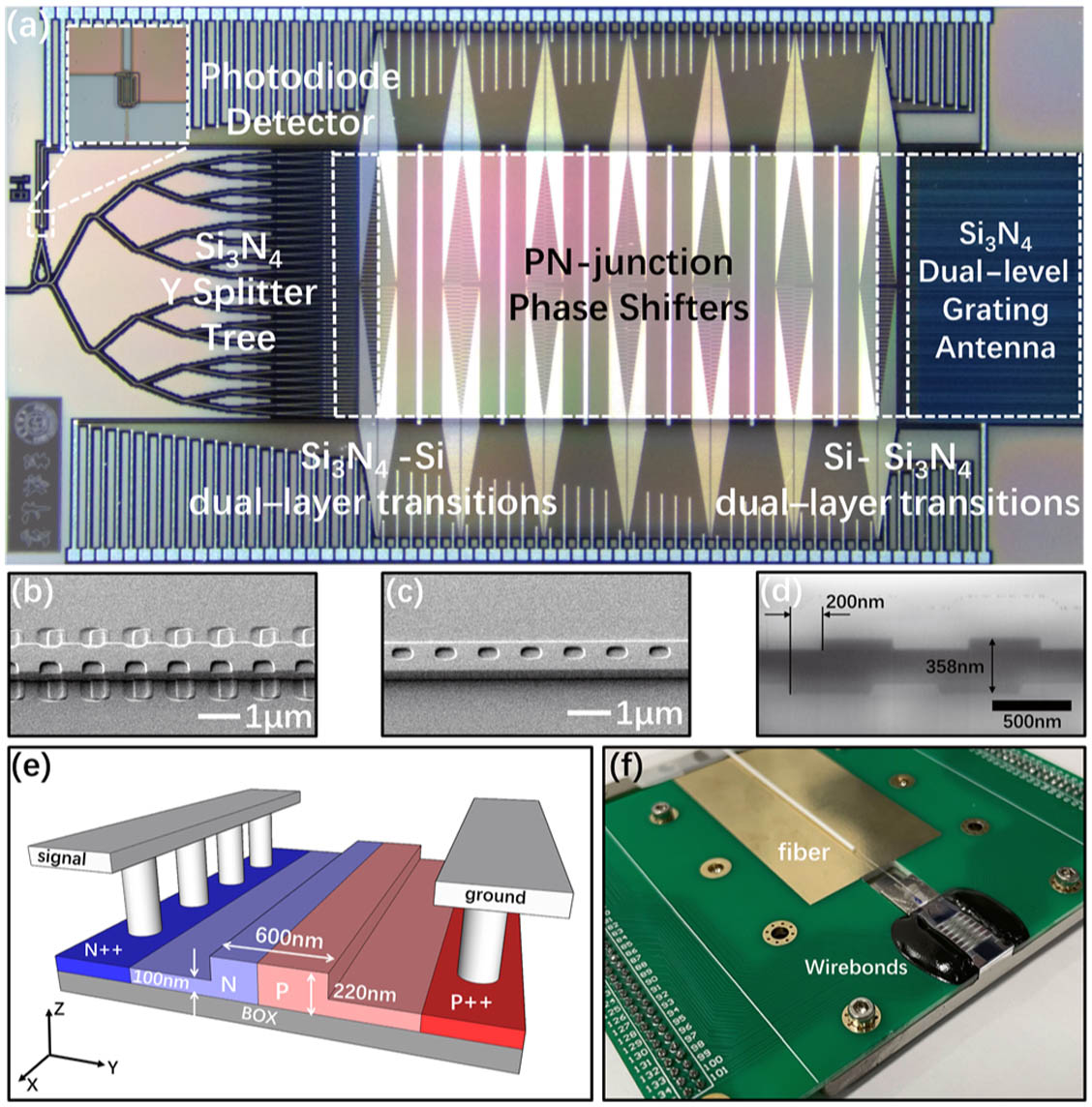
    Figure 1.(a) Optical microscope image of 128-channel OPA. (b) Scanning electron microscope (SEM) image of a fishbone waveguide grating. (c) SEM image of a chain waveguide grating. (d) Transmission electron microscope (TEM) image of dual-level misaligned waveguide grating with the cladding removed. (e) Schematic of a pn junction phase shifter. (f) Electrically and optically packaged 128-channel OPA chip.

    To achieve high resolution and emission efficiency in ψ, we design two dual-level Si3N4 waveguide grating antennas that have fishbone and chain structures. Figures 1(b) and 1(c) are the scanning electron microscope (SEM) pictures of the fishbone and chain structure gratings. To achieve a large effective aperture, the bone width of the fishbone grating and the hole width of the chain grating are gradually changed to achieve apodized grating perturbation. In general, the waveguide grating’s upward and downward emitting powers are equal, which means the emission efficiency is definitely less than 50%. In order to maximize unidirectional grating radiation, the offset between the upper and the lower grating is 200 nm as shown in Fig. 1(d). The grating structure consists of the same grating teeth in both the upper and lower layers etched on a single-layer 358 nm thick Si3N4 waveguide.

    Figure 1(e) shows a schematic diagram of the pn junction phase shifter. It contains p-doped region and n-doped region on ridge Si waveguide. In order to modulate with full 2π phase, the 7 mm long phase shifter with 14 pn junctions in parallel is fabricated via the carrier dispersion effect. The carrier dispersion modulation can provide both low power consumption and high-speed modulation characteristics. The maximum static power consumption of the phase shifter is measured to 1.8 μW, so no extra heat dissipation devices for chips and control electronics are required, and the entire system can be compact. As shown in Fig. 1(f), the chip is electrically and optically packaged. The chip, being die-attached to the printed circuit board (PCB) and wire bonded to the PCB pad, is driven by the control electronics. The single-mode fiber is UV-glued to the on-chip spot mode converter [Fig. 1(f) can be expanded to show the packaged and wire-bonded sections].

    The emitting profiles of the chain and the fishbone grating antennas are analyzed. Figure 2(a) shows the 3D finite difference time domain (FDTD) simulation results for the FWHM of the emitting profile as functions of the etch hole width wp of the chain grating. The schematic diagram for the cross section of a chain grating is depicted in the inset of Fig. 2(a). The inset illustrates that the light scatters out by the etched region centered at the chain grating waveguide. As shown in Fig. 2(a), the FWHM of the emitting profile of the chain grating antenna is increased from 77° to 116° as the wp decreases from 1000 to 150 nm. The inverse proportional relationship indicates that the emitting profile can be broadened effectively by shrinking the wp due to the reduction of the antenna size. Figure 2(b) shows the simulated FWHM of the emitting profile against the bone width wb of the fishbone grating. The inset depicts the schematic cross section of a fishbone grating, illustrating that the light is emitted from the two sides of the fishbone waveguide. Figure 2(b) reveals that the emitting profile of the fishbone grating antenna increases from 59° to 77° as the bone width wb decreases from 800 to 0 nm. The broadening extent of emitting profile is relatively small, since the emission region size of the fishbone grating cannot be effectively reduced.

    Simulation results for emitting profiles of the chain and fishbone grating antennas. (a) The plot for FWHM of the emitting profile against etch hole width wp of a single chain waveguide grating; (b) the plot for FWHM of the emitting profile against bone width wb. The insets of (a) and (b) are the cross sections of the chain and fishbone waveguide gratings. (c) and (d) Far-field simulation result in θ of the chain antenna OPA and the fishbone antenna OPA. Different colors represent the beams at different steering angles with 10° step.

    Figure 2.Simulation results for emitting profiles of the chain and fishbone grating antennas. (a) The plot for FWHM of the emitting profile against etch hole width wp of a single chain waveguide grating; (b) the plot for FWHM of the emitting profile against bone width wb. The insets of (a) and (b) are the cross sections of the chain and fishbone waveguide gratings. (c) and (d) Far-field simulation result in θ of the chain antenna OPA and the fishbone antenna OPA. Different colors represent the beams at different steering angles with 10° step.

    As shown in Figs. 2(c) and 2(d), we simulate the far-field steering performance of the chain antenna OPA and fishbone antenna OPA respectively. The average waveguide spacing is 29.7 μm. Because both gratings are apodized gratings, the shown profiles are average of periodic grating profile. In the research of OPA LIDAR, sidelobe suppression ratio (SMSR) is generally about 10 dB (10% of the maximum) [7,13]. In this paper, the steering range is defined as the width of steering envelope when the main beam intensity drops from the maximum to 20%. That is, during the entire steering process, the main beam intensity is at least twice as high as the sidelobe, so that the main lobe signal can be easily distinguished. Comparing the two profiles, it shows that the steering envelope of chain grating is much broader than that of the fishbone. To avoid beam aliasing in the 180° FOV, a nonuniform waveguide pitch strategy is adopted [24]. With nonuniform antenna spacing, chain antenna OPA theoretical steering range is 140° and fishbone antenna OPA is 100°. Compared to the Si-based antenna, the steering ability of the Si3N4-based antenna is conventionally limited due to the weaker mode confinement. However, through our specially designed chain grating, the Si3N4-based antenna can exhibit an outstanding emitting profile. To our best knowledge, the 140° steering range of the chain antenna OPA is the widest steering for OPA with Si3N4 grating, even surpassing the Si grating [13].

    3. EXPERIMENTS

    A. OPA Device Performance

    According to the far-field condition [25], far-field beam steering test needs to be performed at a long distance, so the beam steering test was measured by rotating the chip. The beam steering performance of chain and fishbone antenna OPAs in θ is shown in Figs. 3(a) and 3(b). The curves show the far-field spot within the ±85° FOV through extracting and stitching the image gray value curves from the infrared camera images in different angles. The chain antenna OPA achieves 140° FOV, which is the widest beam steering range in two-dimensional OPA to our best knowledge. Moreover, our devices emit a high-performance main beam. The SMSR of the chain antenna OPA is 10.26 dB when it steers to 0°, and for the fishbone antenna OPA is 10.63 dB, which are close to the theoretical SMSR of 12.2 dB. SMSR increases slightly with steering angle; when the chain antenna OPA steers to 70°, SMSR is 6.9 dB, and when the chain antenna OPA steers to 50°, SMSR is 7.4 dB.

    (a) and (b) Beam steering performance in θ of the chain antenna OPA and the fishbone antenna OPA. For the chain antenna OPA, sidelobe suppression ratio (SMSR) is 10.26 dB when it steers to 0°; for the fishbone antenna OPA, SMSR is 10.63 dB.

    Figure 3.(a) and (b) Beam steering performance in θ of the chain antenna OPA and the fishbone antenna OPA. For the chain antenna OPA, sidelobe suppression ratio (SMSR) is 10.26 dB when it steers to 0°; for the fishbone antenna OPA, SMSR is 10.63 dB.

    The wavelength control steering result is shown in Fig. 4, with a 1350–1630 nm tunable laser, the chain antenna OPA steers to 19.23° and the fishbone antenna OPA steers to 19.4°. The periods of the fishbone and chain grating antenna are all the same, so the steering angle in ψ is nearly identical.

    Beam steering performance in ψ of the fishbone antenna OPA and chain antenna OPA.

    Figure 4.Beam steering performance in ψ of the fishbone antenna OPA and chain antenna OPA.

    Figures 5(a) and 5(b) are the main lobe cross section curves of the chain antenna OPA 15 m away. The theoretical diffraction spot size is 0.021°×0.027°. The measured far-field FWHM spot size of the chain antenna OPA is 0.021°×0.1°. The vertical spot size is somewhat worse than theory, because the process deviation makes the effective aperture of the chain structure much smaller than the geometric aperture, which enlarges the spot size.

    (a) and (b) Main beam cross section measurement 15 m away from the chain antenna OPA in the θ direction and ψ direction. (c) and (d) Main beam cross section measurement 15 m away from the fishbone antenna OPA in the θ direction and ψ direction. (e) Thirty-seven separate measurements of the beam steered to different angles in about 1° (see Visualization 1 showing the beam steering in θ). (f) Sum of the normalized far-field spot obtained by the fishbone antenna OPA steering with laser wavelength and phase shifters. The entire pattern forms the letters “JLU” in the 0.4°×0.2° FOV (see Visualization 2 showing the 2D beam steering). The image shown has been stripped of camera background noise to improve image contrast.

    Figure 5.(a) and (b) Main beam cross section measurement 15 m away from the chain antenna OPA in the θ direction and ψ direction. (c) and (d) Main beam cross section measurement 15 m away from the fishbone antenna OPA in the θ direction and ψ direction. (e) Thirty-seven separate measurements of the beam steered to different angles in about 1° (see Visualization 1 showing the beam steering in θ). (f) Sum of the normalized far-field spot obtained by the fishbone antenna OPA steering with laser wavelength and phase shifters. The entire pattern forms the letters “JLU” in the 0.4°×0.2° FOV (see Visualization 2 showing the 2D beam steering). The image shown has been stripped of camera background noise to improve image contrast.

    As shown in Figs. 5(c) and 5(d), the measured far-field FWHM spot size of the fishbone antenna OPA is 0.021°×0.029°. In the θ direction, attributing to the nonuniform antenna pitch, we use only 128 waveguides to expand a 4 mm wide aperture, which is conventionally achieved by thousands of waveguides [11,12]. It can significantly reduce power consumption and system complexity. The emission uniformity of the grating is achieved and thus obtains a small divergence angle in ψ, with the same channel number divergence in this design being 10 times smaller [3]. To our knowledge, 0.029° is the smallest divergence in ψ.

    In our previous work, the performances of dual-level chain and fishbone apodized waveguide gratings were studied [17]. The etched region of the fishbone structure is far away from the mode center, so it is robust to process variation. The perturbation of the fishbone grating antenna produces a long and uniform radiation and thus obtains a small divergence in ψ. The etched region of the chain structure is close to the mode center, and the etched hole is very small, so the chain structure is sensitive to process-induced variations. The process deviation makes the effective aperture of the chain structure much smaller than the geometric aperture, so the divergence in ψ is larger than that of the fishbone grating.

    The large aperture of OPAs facilitates high-resolution scanning. As shown in Fig. 5(e), we steer 37 spots in about 1° in θ. The OPA chip is driven by FPGA control electronics, and the point-to-point steering speed in θ is 30 μs. Figure 5(f) is the sum of the normalized far-field spot obtained by the fishbone antenna OPA steering with laser wavelength and phase shifters. The entire pattern forms the letters “JLU” in the 0.4°×0.2° FOV.

    To show the main beam quality across the FOV of the proposed OPAs, the main beam divergence in the θ direction and power efficiency of chain antenna OPA and fishbone antenna OPAs in different steering angles are measured as shown in Figs. 6(a) and 6(b). The main beam power efficiency is defined as the power difference between the main beam power and the input power. Previous studies show that the divergence increases as the OPA steers to a wide angle [7,19], but the device shown here can still exhibit a consistent and good resolution of 0.058° when steered to 70° as shown in Fig. 6(a).

    (a) and (b) Main beam divergence in the θ direction and power efficiency of the chain antenna OPA and fishbone antenna OPA in different steering angles.

    Figure 6.(a) and (b) Main beam divergence in the θ direction and power efficiency of the chain antenna OPA and fishbone antenna OPA in different steering angles.

    The low main beam power efficiency is mainly from the large on-chip insertion loss and the dense sidelobes in the whole FOV. The loss of each part of the chip includes 1.45 dB in the input Si3N4 spot mode coupler, 1.27 dB in the integrated photodetector, 2.52 dB in the seven levels of the Y splitter, 7.45 dB in the pn junction phase shifters, 0.39 dB in the Si3N4SiSi3N4 waveguide dual-layer transitions, 1.6 dB in the waveguide, 2.29 dB in the fishbone grating, and 3.02 dB in the chain grating. For the chain antenna OPA, the system insertion loss is 17.7 dB. For the fishbone antenna OPA, the system insertion loss is 16.97 dB. Nonuniform antenna pitch has intrinsic dense sidelobes [15]. Dense sidelobes in the whole FOV occupy most of the emitting power, which introduce large loss. However, attributed to the nonuniform antenna pitch, only 128 waveguides are used to achieve a 4 mm wide aperture, the super sparse waveguide distribution with 29.7 μm average pitch in this paper results in smaller divergence, and the sidelobe intensity has no significant increase compared to the nonuniform waveguide pitch OPA with 7.246 μm average pitch [13]. Due to small divergence, more concentrated main beam power compensates for the effect of the low power efficiency greatly.

    B. FMCW Ranging Performance

    Using the proposed OPAs, a frequency-modulated continuous-wave (FMCW) ranging system [2628] is performed. The schematic of FMCW LIDAR photonic circuit with triangular modulation is illustrated in Fig. 7(a). OPA is added to the system as the transmitter (TX) and receiver (RX) for on-chip beam collimation. A single frequency laser is modulated by single sideband (SSB) modulator to generate frequency modulated signal; the frequency sweep rate is 30 THz/s, and the modulation bandwidth is 3 GHz from 8.5 to 11.5 GHz. Then the signal is amplified by an erbium-doped fiber amplifier (EDFA) and divided into TX signal and local oscillator (LO) signal. The TX signal is amplified again, and then it is coupled into the fishbone antenna OPA for light collimation. The light reflected from the target is received through a collimator and coherently beaten against the LO. A balanced detector containing a transimpedance amplifier (TIA) converts the light signal into voltage signal, and the multichannel high-speed analog-to-digital converter (ADC) reads the voltage signal, which can be analyzed by digital signal process (DSP). Using coherent detection, a time delay between an RX signal and an LO signal will create a beat frequency. Beat frequency is proportional to the target distance. The target distance is given by D=fc/2α, where f is beat frequency, c is light speed, and α is frequency sweep rate. In fact, the distance D consists of fiber optical length and target distance.

    (a) Schematic of FMCW LIDAR photonic circuit with triangular modulation. (b) Measured beat frequency at various distances with OPA acting as a TX or RX. The inset is the measured beat frequency at various distances at 5 cm intervals. (c) 116 repeated measurements of beat frequency at 100 m.

    Figure 7.(a) Schematic of FMCW LIDAR photonic circuit with triangular modulation. (b) Measured beat frequency at various distances with OPA acting as a TX or RX. The inset is the measured beat frequency at various distances at 5 cm intervals. (c) 116 repeated measurements of beat frequency at 100 m.

    Using the FMCW system, up to 100 m distance was measured. Figure 7(b) shows the measured beat frequency at different distances, a 90% reflectivity scatter plate is placed at a known distance to detect the distance, and the target distance ranges from 5 to 100 m. The fishbone antenna OPA is used as the TX. The inset is the measured beat frequency at various distances at 5 cm intervals. The ranging resolution is 5.09 cm. As shown in Fig. 7(c), distance at 100 m was measured 116 times, and the absolute error of ranging accuracy is 3.38 cm. The reflected signal from 100 m distance is detected with 26 dBm input transmitter power. Such a long detection range benefits from the Si3N4 waveguide having much lower nonlinearity with high input power [29], demonstrating the superiority of the SiN-Si OPA. For detecting distance over 50 m, a silver mirror is used to fold the optical path length.

    Figure 8(a) shows the concept of the FMCW LIDAR photonic circuit for long-reach detection. Figures 8(b) and 8(c) illustrate Fourier transform waveform data of the chain antenna OPA and the fishbone antenna OPA steering to 0° separately at about 100 m. The signal-to-noise pedestal ratios (SPNRs) [30] of the chain antenna OPA and the fishbone antenna OPA are 9.15 dB and 13.07 dB. The difference in the SPNR between the chain antenna OPA and the fishbone antenna OPA is mainly because the divergence in ψ of the chain antenna OPA is larger than that of the fishbone antenna OPA. Admittedly, the signal compared to the pedestal is getting low as the OPA is steered to the edge of the FOV, but our proposed OPA is still capable of 100 m distance measurement at all the angles within the FOV. When the fishbone antenna OPA steers to 50°, the SPNR is 7.36 dB. When the chain antenna OPA steers to 30°, the SPNR is 6.21 dB, which enables the peak processing. When the chain antenna OPA steers to 70°, SPNR is 2.18 dB. In this case, the signal peak is visible, but the ranging accuracy suffers from the noise.

    (a) Concept of FMCW LIDAR photonic circuit for long-reach detection. (b) and (c) Fourier transform waveform data of the chain antenna OPA and fishbone antenna OPA steering to 0° separately at about 100 m. The signal-to-noise pedestal ratios of the chain antenna OPA and fishbone antenna OPA are 9.15 dB and 13.07 dB. (d) Measured beat frequency at different distances with the fishbone antenna OPA acting as a TX or RX.

    Figure 8.(a) Concept of FMCW LIDAR photonic circuit for long-reach detection. (b) and (c) Fourier transform waveform data of the chain antenna OPA and fishbone antenna OPA steering to 0° separately at about 100 m. The signal-to-noise pedestal ratios of the chain antenna OPA and fishbone antenna OPA are 9.15 dB and 13.07 dB. (d) Measured beat frequency at different distances with the fishbone antenna OPA acting as a TX or RX.

    As shown in Fig. 8(d), the beat frequency of the fishbone antenna OPA acting as an RX or TX is almost the same. They prove that the OPA is a promising candidate for transceiving optical signal in coherent detection, attributed to the small divergence, high emission efficiency of the antenna, and low nonlinearity of the Si3N4 waveguide.

    4. DISCUSSION

    To demonstrate wide steering range and high resolution of proposed devices, the performances of the devices are compared to selected results from the literature in Table 1. By comparison, the chain antenna OPA has wide steering range in θ due to the nonuniform waveguide pitch and the wide-angle antenna. Shrinking the etched hole width of the chain grating effectively reduces the transmitter size, so the chain grating can still form a wide emission profile, even though the waveguide size is large. The chain structure provides an applicable solution for low-refractive-index antennas. Although low-refractive-index waveguides are weak in limiting light, such as polymer- and SiON-based waveguides, the chain structure can still effectively reduce the size of the antenna and thus raise the steering ability of antennas.

    Performance Comparison of State-of-the-art OPAs

     Ref. [7]Ref. [12]Ref. [19]Ref. [13]Ref. [14]This Work (Fishbone)This Work (Chain)
    Number of channels641024321288192128128
    Pitch (μm)0.775217.246a129.7a29.7a
    Horizontal steering (°)120459680100100140
    Divergence (°)1.60.032.3×2.80.14×0.140.01×0.0390.021×0.0290.021×0.1
    Aperture (mm)0.04962.0480.032×mb0.927×nb8×54×34×3

    For nonuniform spacing OPAs, waveguide pitch is average pitch;

    m and n are data unknown.

    As shown in Table 1, the largest scale OPA has 8192 channels with 1 μm waveguide pitch. The largest aperture enables the smallest divergence in θ. The nonuniform waveguide pitch method contributes that proposed OPAs have 29.7 μm average pitch, which is the maximum pitch to our knowledge. So the divergence in θ is small with fewer channels, which reduces the complexity of the control circuit. The divergence in ψ of the fishbone antenna OPA is the smallest in Table 1 due to the large effective aperture.

    Further research should be undertaken to investigate how to achieve small divergence and wide steering angle simultaneously. The chain antenna OPA has the widest steering range in θ, but the divergence in ψ is larger than expected due to the sensitivity to process variations. The etch hole width of a chain waveguide grating antenna is apodized from 150 nm, which is difficult to process. An improvement for process tolerance is to apodize the duty cycle [18] instead of the hole width. The suitable hole width can be set for better process tolerance and wider emission profile.

    The concentrated main beam obtained by super sparse waveguide pitch compensates for the chip loss, which is beneficial to long-range detecting. Reducing chip loss and maintaining small divergence at the same time should be considered in further study.

    5. CONCLUSION

    In conclusion, we have demonstrated two 128-channel OPAs with large steering range and small divergence. Compared with the fishbone structure, the chain antenna OPA has a unique advantage in expanding the beam steering range. It achieves 140° steering, which is the widest horizontal steering range for two-dimensional OPAs to our best knowledge. In the phase control horizontal axis, the devices achieve a small divergence by virtue of a 4 mm aperture. In the wavelength control vertical axis, the Si3N4 waveguide grating achieves high emitting efficiency and uniform radiation, increasing the effective aperture and reducing the divergence. The divergence of the fishbone antenna OPA is 0.021°×0.029°, and that of the chain antenna OPA is 0.021°×0.1°. When the chain antenna OPA is steered to 70°, the divergence in the phase control axis is still less than 0.058°. The chain structure is sensitive to variations in fabrication, leading to a different divergence from design. In addition, the chain antenna OPA and fishbone antenna OPA are embedded into an FMCW system for distance measurement. The concentrated main beam obtained by super nonuniform waveguide pitch compensates for the chip loss effectively, and the proposed OPAs steering to the edge of the FOV can also detect to 100 m. Moreover, the fishbone antenna OPA acts as a transmitter and a receiver. 100 m ranging distance is achieved, the absolute error of ranging accuracy is 3.38 cm, and the ranging resolution is 5.09 cm. Such wide-angle and high-resolution beam steering boosts the implementation of automotive LIDAR.

    References

    [1] S. A. Miller, Y. C. Chang, C. T. Phare, C. S. Min, M. Lipson. Large-scale optical phased array using a low-power multi-pass silicon photonic platform. Optica, 7, 3-6(2020).

    [2] C. V. Poulton, M. J. Byrd, P. Russo, E. Timurdogan, M. Khandaker, D. Vermeulen, M. R. Watts. Long-range LiDAR and free-space data communication with high-performance optical phased arrays. IEEE J. Sel. Top. Quantum Electron., 25, 7700108(2019).

    [3] N. A. Tyler, D. Fowler, S. Malhouitre, S. Garcia, P. Grosse, W. Rabaud, B. Szelag. SiN integrated optical phased arrays for two-dimensional beam steering at a single near-infrared wavelength. Opt. Express, 27, 5851-5858(2019).

    [4] Q. Wang, S. Wang, L. Jia, Y. Cai, M. Yu. Silicon nitride assisted 1×64 optical phased array based on SOI platform. Opt. Express, 29, 10509-10517(2021).

    [5] L. Zhang, Y. Li, M. Tao, Y. Wang, Y. Hou, B. Chen, Y. Li, L. Qin, F. Gao, X. Luo. Large-scale integrated multi-lines optical phased array chip. IEEE Photon. J., 12, 6601208(2020).

    [6] C. P. Hsu, B. Li, B. Solano-Rivas, A. R. Gohil, V. Donzella. A review and perspective on optical phased array for automotive LiDAR. IEEE J. Sel. Top. Quantum Electron., 27, 8300416(2021).

    [7] C. T. Phare, C. S. Min, J. Sharma, S. Ahasan, M. Lipson. Silicon optical phased array with grating lobe-free beam formation over 180 degree field of view. CLEO: Science and Innovations, SM3I.2(2018).

    [8] W. L. Stutzman, G. A. Thiele. Antenna Theory and Design(2013).

    [9] S. J. Orfanidis. Electromagnetic Waves and Antennas(2016).

    [10] C. V. Poulton, M. J. Byrd, B. Moss, E. Timurdogan, M. R. Watts. 8192-element optical phased array with 100° steering range and flip-chip CMOS. CLEO: Applications and Technology, JTh4A.3(2020).

    [11] C. V. Poulton, M. J. Byrd, M. Raval, S. Zhan, M. R. Watts. Large-scale visible and infrared optical phased arrays in silicon nitride. CLEO: Science & Innovations, STh1M.1(2017).

    [12] S. W. Chung, H. Abediasl, H. Hashemi. A monolithically integrated large-scale optical phased array in silicon-on-insulator CMOS. IEEE J. Solid-State Circuits, 53, 275-296(2017).

    [13] D. N. Hutchison, S. Jie, J. K. Doylend, R. Kumar, H. Rong. High-resolution aliasing-free optical beam steering. Optica, 3, 887-890(2016).

    [14] C. S. Min, A. Mohanty, K. Watson, G. R. Bhatt, M. Lipson. Chip-scale blue light phased array. Opt. Lett., 45, 1934-1937(2020).

    [15] R. Fatemi, A. Khachaturian, A. Hajimiri. A nonuniform sparse 2-D large-FOV optical phased array with a low-power PWM drive. IEEE J. Solid-State Circuits, 54, 1200-1215(2019).

    [16] M. Raval, C. V. Poulton, M. R. Watts. Unidirectional waveguide grating antennas with uniform emission for optical phased arrays. Opt. Lett., 42, 2563-2566(2017).

    [17] B. Chen, Y. Li, L. Zhang, Y. Li, X. Liu, M. Tao, Y. Hou, H. Tang, Z. Zhi, F. Gao, X. Luo, G. Lo, J. Song. Unidirectional large-scale waveguide grating with uniform radiation for optical phased array. Opt. Express, 29, 20995-21010(2021).

    [18] M. Zadka, Y.-C. Chang, A. Mohanty, C. T. Phare, S. P. Roberts, M. Lipson. On-chip platform for a phased array with minimal beam divergence and wide field-of-view. Opt. Express, 26, 2528-2534(2018).

    [19] P. Wang, G. Luo, Y. Xu, Y. Li, J. Pan. Design and fabrication of SiN-Si dual-layer optical phased array chip. Photon. Res., 8, 912-919(2020).

    [20] S. H. Kim, J. B. You, Y. G. Ha, G. Kang, H. H. Park. Thermo-optic control of the longitudinal radiation angle in a silicon-based optical phased array. Opt. Lett., 44, 411-414(2019).

    [21] A. Masood, M. Pantouvaki, G. Lepage, P. Verheyen, J. V. Campenhout, P. Absil, D. V. Thourhout, W. Bogaerts. Comparison of heater architectures for thermal control of silicon photonic circuits. 10th International Conference on Group IV Photonics, 83-84(2013).

    [22] X. Tu, T.-Y. Liow, J. Song, X. Luo, Q. Fang, M. Yu, G.-Q. Lo. 50-Gb/s silicon optical modulator with traveling-wave electrodes. Opt. Express, 21, 12776-12782(2013).

    [23] S. Y. Siew, B. Li, F. Gao, H. Y. Zheng, G. Q. Lo. Review of silicon photonics technology and platform development. J. Lightwave Technol., 39, 4374-4389(2021).

    [24] D. Zhuang, L. Zhagn, X. Han, Y. Li, Y. Li, X. Liu, F. Gao, J. Song. Omnidirectional beam steering using aperiodic optical phased array with high error margin. Opt. Express, 26, 19154-19170(2018).

    [25] D. Kwong, A. Hosseini, Z. Yang, R. T. Chen. 1 × 12 unequally spaced waveguide array for actively tuned optical phased array on a silicon nanomembrane. Appl. Phys. Lett., 99, 051104(2011).

    [26] C. V. Poulton, Y. Ami, D. B. Cole, M. J. Byrd, R. Manan, V. Diedrik, M. R. Watts. Coherent solid-state LIDAR with silicon photonic optical phased arrays. Opt. Lett., 42, 4091-4094(2017).

    [27] D. Pierrottet, F. Amzajerdian, L. Petway, B. Barnes, G. Lockard, M. Rubio. Linear FMCW laser radar for precision range and vector velocity measurements. MRS Proc., 1076, 1076-K04-06(2008).

    [28] C. Rogers, A. Y. Piggott, D. J. Thomson, R. F. Wiser, I. E. Opris, S. A. Fortune, A. J. Compston, A. Gondarenko, F. Meng, X. Chen, G. T. Reed, R. Nicolaescu. A universal 3D imaging sensor on a silicon photonics platform. Nature, 590, 256-261(2021).

    [29] D. Tan, K. Ikeda, P. C. Sun, Y. Fainman. Group velocity dispersion and self phase modulation in silicon nitride waveguides. Appl. Phys. Lett., 96, 061101(2010).

    [30] A. Martin, D. Dodane, L. Leviandier, D. Dolfi, J. Bourderionnet. Photonic integrated circuit based FMCW coherent LiDAR. J. Lightwave Technol., 36, 4640-4645(2018).

    Yingzhi Li, Baisong Chen, Quanxin Na, Qijie Xie, Min Tao, Lanxuan Zhang, Zihao Zhi, Yuxuan Li, Xiaobin Liu, Xianshu Luo, Guoqiang Lo, Fengli Gao, Xueyan Li, Junfeng Song. Wide-steering-angle high-resolution optical phased array[J]. Photonics Research, 2021, 9(12): 2511
    Download Citation