D. Klir1,*, S. L. Jackson2, A. V. Shishlov3, V. A. Kokshenev3..., K. Rezac1, A. R. Beresnyak2, R. K. Cherdizov3, J. Cikhardt1, B. Cikhardtova1, G. N. Dudkin4, J. T. Engelbrecht2, F. I. Fursov3, J. Krasa5, J. Kravarik1, P. Kubes1, N. E. Kurmaev3, V. Munzar1, N. A. Ratakhin6, K. Turek7 and V. A. Varlachev4|Show fewer author(s)
Abstract
Z-pinch experiments with a hybrid configuration of a deuterium gas puff have been carried out on the HAWK (NRL, Washington, DC) and GIT-12 (IHCE, Tomsk) pulsed power generators at 0.7 MA and 3 MA currents, respectively. On GIT-12, neutron yields reached an average value of 2 × 10¹² neutrons, and deuterons were accelerated up to an energy of 30 MeV. This was 50 times the ion energy provided by the generator driving voltage of 0.6 MV and the highest energy observed in z-pinches and dense plasma foci. To confirm these unique results independently on another device, we performed several experimental campaigns on the HAWK generator. Comparison of the experiments on GIT-12 and HAWK helped us to understand which parameters are essential for optimized neutron production. Since the HAWK generator is of a similar pulsed power architecture as GIT-12, the experiments on GIT-12 and HAWK are important for the study of how charged-particle acceleration scales with the current.I. INTRODUCTION
Z-pinches are known to be efficient sources of x-rays, neutrons, and charged particles.1,2 As early as the 1950s, z-pinches were investigated as a potential route to thermonuclear fusion. The first compressional z-pinches produced a large number of neutrons, which were believed to originate from the D(d,n)3He fusion reaction.3–5 However, shortly afterward, plasma physicists found out that the fusion neutrons were actually produced by a beam–target mechanism, and the fraction of thermonuclear neutrons was negligible (experimental evidence for a contribution from a thermonuclear mechanism in deuterium z-pinches has been provided only recently6,7). The conclusion that the neutrons were not of thermonuclear origin implied that compressional z-pinches could not be used for energy production.8 As a result, more complex schemes for magnetic confinement of plasmas, such as stellarators and tokamaks, were preferred for controlled thermonuclear fusion research. Nevertheless, in the following years, z-pinches remained attractive owing to their efficient neutron production. Since then, with the aim of achieving even higher neutron yields, various configurations based on the z-pinch effect have been tested. In particular, a dense plasma focus (DPF) with a deuterium filling has been optimized for a high neutron yield.9–12
DPFs demonstrated a very promising dependence of a neutron yield per unit length of a plasma column on peak current as Yn/l ∝ I4 up to I = 1 MA.13 Unfortunately, this favorable scaling law does not extend above 1 MA. A successful experiment on the 2 MA DPF 6-1/2 plasma focus device at LANL in 197314 was not reproduced, and a “saturation” of neutron yields between 1011 and 1012 was observed on the mega-ampere plasma focus devices at Limeil,11 Frascati, Swierk, and Stuttgart.15 One possible explanation of this saturation is the significant drop in “pinch” current due to a low impedance of low-voltage megajoule capacitive discharges.16 Other hypotheses have been based on problems caused by inhomogeneous breakdowns or current losses at an insulator during the main neutron emission in mega-ampere DPFs.17 Further, it is questionable if optimal initial conditions of small- and medium-size DPFs, e.g., a drive parameter,18,19 are valid at mega-ampere currents.20 In “standard” dense plasma foci, all phases are interconnected and it is not easy to make independent changes to the conditions required for optimal breakdown, rundown, and pinch phases. Taking all of the above-mentioned facts into account, we decided to investigate deuterium gas-puff z-pinches on higher-impedance pulsed-power devices. Deuterium gas puffs possess the advantage of causing no difficulties with an insulator, namely, with its conditioning before breakdown and early re-strikes during the pinch phase. In addition, deuterium gas-puff z-pinches enable the exploration of a broader range of initial conditions than plasma foci can. On the other hand, the existence of more options makes the search for optimal parameters to provide high neutron yields a more challenging task.
To find the optimal parameters of a deuterium gas-puff z-pinch, we have carried out experiments on the 3 MA GIT-12 generator at the Institute of High Current Electronics (IHCE) in Tomsk.21,22 In our first experiments, we determined the optimal mass of deuterium gas.20,23 Later, we wanted to improve the initial conditions by forming a homogeneous, uniformly conducting layer at the beginning of the high-voltage discharge. For this purpose, we used 48 cable guns to inject an outer hollow cylindrical plasma shell around an inner gas puff.24 Giuliani and Commisso in their review paper25 included this configuration among hybrid gas puffs. In comparison with previous deuterium gas-puff experiments at the same current, the maximum neutron yield in our hybrid gas puff was increased by one order of magnitude (with an average value of 2 × 10¹² neutrons24,26), and deuterons were accelerated up to an energy of 30 MeV.27 This is 50 times the ion energy provided by the generator driving voltage of 0.6 MV and the highest energy observed in z-pinches and dense plasma foci (compare Ref. 27 and Refs. 28–30). The unprecedented ion energies enabled us to use novel diagnostic techniques to obtain comprehensive information about ions and to discuss various hypotheses regarding ion acceleration.31 In a recent paper,31 we have presented a mechanism based on Trubnikov’s idea of the disruption of a conduction current.32 Acceleration of charged particles by current disruptions has often been observed in laboratory and space plasmas (see Refs. 33–37 and references therein). However, there could be miscellaneous causes of the current disruption in z-pinches and dense plasma foci (implosion of necks,5,38–42 anomalous resistivity,43–47 etc.). In our case, a significant current drop is attributed to a transition from a low-impedance plasma to a space-charge-limited flow (or self-magnetic insulation) in a gap formed after the ejection of plasmas from m = 0 constrictions. This behavior is analogous to the main principle of plasma-filled diodes48–51 and may also play an important role in dense plasma foci and x-pinches.2,52 On GIT-12, we used our improved knowledge of the ion acceleration mechanism to increase neutron yields above 1013 at a current of 2.7 MA with the help of a neutron-producing catcher.53
The experiments on the GIT-12 generator provided us with several unique results. However, as in any important physical experiment, it is highly desirable to confirm the results on another device. For this purpose, we have performed experimental campaigns on the HAWK generator at the U.S. Naval Research Laboratory in Washington. In this paper, we will present a comparison of the experiments on GIT-12 and HAWK. The comparison of the experiments on GIT-12 and HAWK has helped us to understand which parameters are essential for optimized neutron production. The experiments on GIT-12 and HAWK are also important for studies on how charged-particle acceleration scales with current.
II. APPARATUS AND DIAGNOSTICS
A. Current generators
Both the GIT-1221 and HAWK54 machines are of a similar pulsed power architecture. Their common characteristic feature is a high inductance, namely, 110 nH on GIT-12 and 607 nH on HAWK, which implies a relatively small influence of z-pinch loads on current waveforms. The GIT-12 capacitors were charged to 50 kV and stored a total energy of 2.6 MJ. In a microsecond regime, the current reached a peak of about 4.7 MA with a current rise time of about 1.7 µs in a short-circuit load. In our GIT-12 experiments, hybrid gas puffs imploded onto the axis before the peak current at about 800 ns, when the current reached 2.7 MA. The HAWK generator resembles a single module of GIT-12. At an 80 kV charging voltage, HAWK stored an energy of 0.22 MJ and delivered a 0.64 MV, 0.7 MA pulse to a load within a 1.2 µs rise time.
B. Z-pinch loads
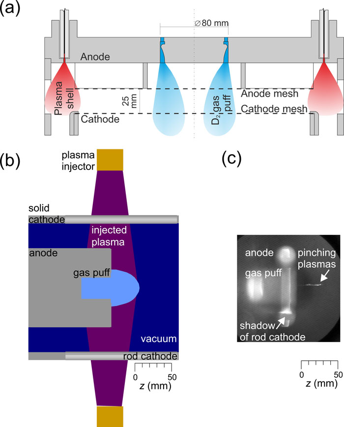
The optimized neutron production on GIT-12 was obtained with a hybrid deuterium gas puff. In this configuration, an annular deuterium gas puff of diameter 8 cm was surrounded by an outer hollow cylindrical plasma shell of diameter 35 cm [see Fig. 1(a)]. The main idea behind using the plasma shell was to form a homogeneous, uniformly conducting current sheath at a large initial radius prior to implosion (see our previous paper24 for more details). A hollow cylindrical plasma shell consisting of hydrogen and carbon ions was injected between the electrodes by 48 polyethylene cable guns. The optimal linear mass of the plasma shell was about 5 µg/cm, whereas the total linear mass of deuterium gas in single- or double-shell gas puffs was about 100 µg/cm. The time delay between the gas valve opening and the triggering of the generator was set to 300 µs. The deuterium gas was injected from a concentric convergent–divergent nozzle of throat width 1 mm. The nozzles were placed on the anode side about 35 mm from the anode mesh. The anode–cathode gap varied between 20 mm and 28 mm in most of the shots. Both the anode and cathode were formed from stainless-steel mesh with a transparency of about 70%. The mesh was made of 0.5 mm diameter wires. Owing to multiple reflections of a fraction of the gas by the mesh electrodes, the gas was spread out over a large area.31,55

Figure 1.Schematics of experimental setups with hybrid deuterium gas puffs on (a) GIT-12 and (b) HAWK. (c) Time-integrated x-ray pinhole image detected by an unfiltered image plate in HAWK shot 5010.
The HAWK generator was used to drive a similar z-pinch configuration. However, instead of polyethylene cable guns, three Marshall guns were employed to inject a deuterium plasma shell radially between coaxial electrodes. The anode and cathode diameters were 10.5 cm and 17.3 cm, respectively. The time delay between the triggering of the Marshall guns and the HAWK generator was usually set between 3.0 µs and 5.5 µs so that the arrival of the plasma at the center of the space between the electrodes was detected by an axially viewing interferometer between 1.5 µs and 4 µs, respectively, before the beginning of the main Hawk current pulse.56 The total plasma shell mass from the three guns was ∼1 µg/cm. As shown in Fig. 1(b), the additional mass of neutral deuterium gas was puffed by an on-axis valve of diameter 3.8 cm or 4.45 cm placed inside the central anode.57 In a recent experimental campaign with reproducible high neutron yields, the mass per unit length was about 30 µg/cm (estimated by matching measured implosion times to MHD simulations in shots with the central gas puff only). Unlike the experimental setup on GIT-12, there was no cathode mesh on HAWK. Therefore, the initial parameters of the HAWK load might be considered as the radial phase of dense plasma foci where the length of the imploding plasma column is not fixed.58 In Fig. 1(c), we can see that the length of radiating plasmas was about 4 cm. As well as the pinching plasmas, Fig. 1(c) shows the x-rays produced by the interaction of relativistic electrons with the anode. A detailed description of the experimental setup is the subject of forthcoming papers.56,59
C. Diagnostics
The dynamics of deuterium gas puff z-pinches on HAWK and GIT-12 were studied using various electrical, optical, x-ray, gamma, ion, and neutron diagnostics.53,59 The results presented in this paper were obtained by the following set of diagnostic tools.
First, electrical characteristics and the power input into the z-pinch loads on GIT-12 and HAWK were monitored by high-voltage, current, and dI/dt probes.
Second, the x-ray radiation on HAWK was recorded by a time-integrated pinhole camera, with a stack of image plates as detectors. The first image plate was unfiltered to detect soft x-rays above 1 keV. This plate also served as a filter for the second image plate, which recorded ≳10 keV hard x-rays.
Third, information about ion emission was obtained by a detector placed on the axis [see Fig. 3(a)]. This detector simultaneously measured the angular, spatial, and spectral properties of the ion emission.31
Fourth, neutron energies and the emission time of fast neutrons as well as high-energy (>1 MeV) photons were measured by neutron time-of-flight (ToF) detectors in the radial and axial directions. On GIT-12, four radial and one axial neutron ToF detectors were each composed of a BC-408 fast plastic scintillator and a Hamamatsu H1949-51 PMT assembly.60 On HAWK, three radial and one axial neutron ToF detectors were each composed of a NE-111 plastic scintillator and an Amperex PMT tube.61–63 The temporal resolution of the neutron detectors was about 5 ns. The time of neutron production was estimated from the nearest radial neutron detector, which was placed as close to the neutron source as possible, namely, at 1.26 m on HAWK and 2.00 m on GIT-12. Neutron energy spectra were determined mainly by the most distant radial detector, namely, at 10.82 m on HAWK and 25.79 m on GIT-12. To prevent hard x-rays from saturating the photomultipliers, the detectors were shielded with between 5 cm and 20 cm of lead.
Fifth, neutron fluences were measured by activation counters. On HAWK, two rhodium activation counters61,64,65 were used in the radial and axial directions. On GIT-12, a silver activation counter was used in the radial direction only. On GIT-12, we performed the post-shot gamma spectroscopy of samples activated by neutrons with a NaI:Tl scintillator detector and a high-purity Ge detector. Aluminum, copper, indium, zirconium, and other samples were placed at various directions and distances for neutron fluence measurements above specific threshold energies.66
Finally, an RDS-31S gamma-radiation detector67 measured the time evolution of the dose rate caused by 0.06–6 MeV photons at distances of 0.35 m and 1.00 m from the center of the experimental chamber on HAWK and GIT-12, respectively.
III. RESULTS
A. Z-pinch dynamics and neutron emission
The dynamics of deuterium gas-puff z-pinches have been studied on GIT-12 since 2011. One of the first essential results was that the highest neutron yields were achieved with a relatively low mass of deuterium gas and with an outer hollow cylindrical plasma shell injected at a large radius. As shown in Fig. 2(a), the low linear density of a gas puff led to an early implosion at about 800 ns, i.e., before the current reached its peak (it was not possible to match the stagnation to the peak current, since the dimensions of the vacuum chamber prevented the plasma shell from being moved any further outward while maintaining the optimal mass). After implosion, one 10–20 ns, >2 MeV high-energy bremsstrahlung pulse was produced and detected by our neutron ToF detectors placed behind 20 cm of lead. A broad neutron energy spectrum and side-on neutron energies up to 30 MeV were manifested in the broadening of neutron ToF signals. Figure 2(b) shows how the neutron ToF signal was shifted and broadened with increasing distance from the neutron source, namely, at 2.00 m and 5.63 m. The average neutron yield was 2 × 10¹² per shot.24
Figure 2.(a) Current and voltage waveforms and (b) radial neutron ToF signals at 2.00 m and 5.63 m in a hybrid deuterium gas puff z-pinch on GIT-12. Shot 2115, plasma shell on a single-shell D2 gas puff, (2.7 ± 0.5) × 1012 neutrons. (c) Current and voltage waveforms and (d) radial neutron ToF signals at 1.29 m and 3.72 m in a hybrid deuterium gas-puff z-pinch on HAWK. Shot 4999, on-axis D2 gas puff with plasma shell from Marshall guns, (5.0 ± 2.0) × 1010 neutrons. All signals were adjusted to account for different transit times from each detector to the oscilloscopes. The ToF of photons and the electron transit time of the photomultiplier tubes were also included.
On HAWK, the optimal conditions had to be found. For that purpose, we performed shots with various initial parameters of the Marshall guns and the on-axis gas-puff valve. Similarly to GIT-12, the highest neutron yields and the highest neutron energies were observed in shots with a lower-mass on-axis gas puff surrounded by a plasma shell. B-dot probes and time-resolved imaging have not yet been used on HAWK. Therefore, we have not been able to measure the influence of the plasma shell on the current layer and implosion dynamics on HAWK directly. Nevertheless, when the Marshall guns on HAWK injected the deuterium plasma shell radially between the coaxial electrodes, the maximum insulator voltage could reach almost 800 kV (i.e., higher than the HAWK output voltage), and a relatively high fraction of the generator energy was deposited into the z-pinch load. Figure 2(c) shows shot 4999, where the Marshall guns were triggered 5.5 µs before the HAWK generator. The low masses of Marshall-gun plasmas and deuterium gas in shot 4999 led to the early implosion, which occurred before the peak of the HAWK current at 800 ns. During the first dip in dI/dt, one 10 ns pulse of >1 MeV bremsstrahlung radiation was detected. The neutron yield reached (5.0 ± 2.0) × 1010. From the onset of the neutron signal at 1.3 m and 3.7 m in Fig. 2(d), we estimated the highest energy of neutrons emitted radially as 13 MeV. Such energetic neutrons were produced by nuclear reactions initiated by multi-MeV deuterons. Therefore, we characterize the ion emission in Subsection III B.
B. Ion emission
The ion emission on GIT-12 was characterized using a variety of ion diagnostics.27 One of the most useful diagnostic tools proved to be an on-axis detector that simultaneously measured the angular, spatial, and spectral properties of ion emission.31,53 Therefore, we decided to use this detector also on HAWK. The detector is shown schematically in Fig. 3(a). The angular distribution of ion emission was measured by a beam-profile detector consisting of large samples of radiochromic films and CR-39 detectors placed at about 10 cm and 20 cm from the ion sources on GIT-12 and HAWK, respectively. The effective area of the detectors was reduced by a shielding mask and three cutouts. At the center of each cutout, there was a pinhole that provided the spatial distribution of the ion source. Three pinholes were used to estimate ion emission anisotropy. The ion pinhole camera used a stack consisting of absorbers, various radiochromic films, and CR-39 solid-state nuclear track detectors. The ion energies detected by the beam-profile detector and the pinhole cameras were calculated using the SRIM code.68 The measurement by the beam-profile detector will be described first.
Figure 3.Measurement of ion-beam profile. (a) Schematic of the axial ion detector on GIT-12. (b) Image of the ion-beam profile on GIT-12 recorded at 10 cm by a CR-39 detector behind a 1 mm aluminum-alloy (EN AW 2017) absorber, three HD-V2 films, 0.1 mm and 0.5 mm Al absorbers, and one 0.49 mm CR-39 detector on shot 1947. (c) Image of the ion-beam profile on HAWK recorded at 20 cm by a CR-39 detector behind a 0.1 mm Al absorber on shot 4983. The detector darkness is proportional to the ion flux.
1. Stripes in beam-profile images
The spatial profiles of our ion beams were measured by large samples of radiochromic films and CR-39 detectors. The advantage of CR-39 detectors is that they are practically insensitive to x-rays and electrons. Since our z-pinch loads on HAWK and GIT-12 produced a considerable number of electrons and bremsstrahlung photons, we present the results detected by the CR-39 detectors in Fig. 3. In the shots shown in Fig. 3, deuterons on GIT-12 and HAWK exceeded energies of 27 MeV and 4.5 MeV, respectively. Usually, the beam profile consisted of many radial lines distributed around the center of the beam. On HAWK, individual radial lines were also present, but sometimes they were less visible, as shown in Fig. 3(c). In most of the shots, the detected ion emission was not fully axisymmetric, and the radial lines formed the shape of a fan. Further details about the ion emission were obtained with an ion pinhole camera, which will be presented next.
2. Rings in ion pinhole images
Ion pinhole cameras were used to measure the spatial distribution of ion sources. Since the ion emission in our experiments was anisotropic, it was desirable to use a camera with multiple pinholes. A schematic of our three-pinhole camera used on GIT-12 is shown in Fig. 3(a), and the results from GIT-12 and HAWK are displayed in Fig. 4. Figures 4(a) and 4(b) show the pinhole images produced by deuterons with energies >7.5 MeV and ≳1 MeV on GIT-12 and HAWK, respectively. The characteristic feature of the pinhole images on both devices was the emission from a central spot and from circular structures of a relatively large diameter. Explanation of the ring-like structures in ion pinhole images has been the subject of our recent research. In Ref. 69, we attributed the origin of a ring of a particular diameter to the geometry of the electrodes and to the distribution of the current density before current disruption. Whatever the explanation is, at this point, we would like to show similarities and differences between the pinhole images on HAWK and GIT-12 in Fig. 4. The most visible difference between the devices is that there was a shadow of squares in the emission on GIT-12. This shadow was created by the cathode mesh. Otherwise, the pinhole images on GIT-12 and HAWK exhibited very similar behavior. The position of the central spot with respect to the circle varied, exhibiting a dependence on the line of sight. The cathode mesh on GIT-12 helped us to recognize that the central spot moved with the changing line of sight faster than the position of the ring. For the ring, the emission intensity varied strongly along the circle and depended on the position of the pinhole. On HAWK, we observed a similar emission anisotropy, taking into account the fact that the three pinhole images in Fig. 4(b) display various deuteron energies around 1 MeV. The pinhole images produced by more energetic deuterons will be described next.
Figure 4.Measurement of spatial distribution and emission anisotropy of ion sources. (a) Images from a three-pinhole camera on GIT-12 (0.55 magnification and 0.26 mm pinhole diameter) recorded by HD-V2 film behind a 20 µm Al absorber and two HD-V2 films on shot 1947. Spatial scales correspond to the plane of the cathode mesh. (b) Images from the three-pinhole camera on HAWK (0.25 magnification and 0.4 mm pinhole diameter) recorded by the first HD-V2 film behind three different absorbers (6 µm Kimfoil, 10 µm Al, 20 µm Al). Spatial scales correspond to the plane of the anode end.
3. Individual spots at higher ion energies
The anisotropy of ion emission was nicely visible in the pinhole images at higher ion energies. Figure 5 displays the pinhole images at deuteron energies of >27 MeV and >7 MeV on GIT-12 and HAWK, respectively. These energies are close to the endpoint energies on both devices. In both cases, the ion pinhole images show that the most-energetic ions were emitted from individual localized spots.
Figure 5.Measurement of spatial distribution and emission anisotropy of high-energy ion sources. (a) Images from the three-pinhole camera on GIT-12 (0.59 magnification and 0.45 mm pinhole diameter) recorded by EBT-3 film behind 30 µm and 470 µm Al absorbers, seven HD-V2 films, two EBT-3 films, and two 0.58 mm CR-39 detectors on shot 1830. Spatial scales correspond to the plane of the cathode mesh. (b) Images from the three-pinhole camera on HAWK (0.25 magnification and 0.4 mm pinhole diameter) recorded by EBT-3 film behind three different absorbers (6 µm Kimfoil, 10 µm Al, 20 µm Al) and one HD-V2 film. Spatial scales correspond to the plane of the anode end. Note: The EBT-3 films used on HAWK and GIT-12 originated from two different lots.
The number and position of detected individual ion sources depended on the line of sight of the pinhole cameras. In our previous paper,31 this was explained by the divergence of ion microbeams emitted from localized sources distributed along the circle. The main idea was that collimated emission from each localized source was deflected by azimuthal magnetic and radial electric fields and produced a radial line in the beam-profile detector (see Fig. 3). Then each individual source would be detected by the pinhole camera if the deflected beam hit a pinhole. As a result, the pinhole near the focus of all deflected microbeams, e.g., the bottom right pinhole image in Fig. 5(a), saw the largest number of localized ion sources. The off-axis pinhole could detect sources that lay in the plane determined by the pinhole and the z-pinch axis. Other sources could be seen only if the initial microbeam divergence was sufficiently large.
The pinhole images in Figs. 4 and 5 show an abundance of deuterons with energies above 1 MeV. These deuterons could induce nuclear reactions not only with (mostly stationary) target deuterons inside the z-pinch, but also with other elements inside the experimental chamber. The nuclear reactions producing non-DD neutrons on GIT-12 were described by Cikhardt et al.66 Besides the neutron production, the high-energy deuterons could also cause the activation of an experimental chamber, which will be presented in Subsection III C.
C. Activation of experimental chambers
Activation monitoring has been used on HAWK and GIT-12 as part of the personnel safety systems. The time evolution of the dose rate due to photons in the range between 0.6 MeV and 6 MeV emitted during the post-shot radioactive decay of the experimental hardware was measured by an RDS-31S gamma-radiation detector.67 The detector was placed in the radial direction at 0.35 m and 1.00 m from the z-pinch on HAWK and GIT-12, respectively. The results from two shots, i.e., one on GIT-12 and one on HAWK, are displayed in Fig. 6(a). It can be seen that the dose rates after shots on HAWK and GIT-12 decayed with the same temporal characteristics. Both curves in Fig. 6(a) were fitted by multiple exponential decays with separate half-lives and amplitudes. On GIT-12 and HAWK, the most significant decay had a half-life of (2.20 ± 0.06) min (±2σ). This half-life corresponds to the 28Al isotope, which was likely produced by nuclear reactions of accelerated deuterons with aluminum material. Figure 6(b) shows that the 27Al(d,p)28Al reaction (with a Q-value of +5.5 MeV) has a relatively high cross-section of more than 10 mb for 2 MeV deuterons. Since most of the ions in our experiments were accelerated toward the axial ion diagnostics (as shown in Fig. 3), we suppose that the 28Al isotope production came from the axial detector’s cover layer, which was usually made of an aluminum alloy (EN AW 2017). Here we should note that this aluminum cover was also a source of fast neutrons, since the 27Al(d,p)28Al reaction is accompanied by another reaction 27Al(d,n)28Si of comparable probability66 and a positive Q-value of 9.361 MeV.
Figure 6.(a) Time evolution of a post-shot dose rate measured at 0.35 m and 1.00 m on HAWK (black line, shot 5008, 1.4 × 10¹⁰ neutrons) and GIT-12 (red line, shot 2131, 3.8 × 10¹² neutrons). The sampling interval was 10 s. The time of the shots corresponds to t = 0 s. (b) Energy dependence of the 27Al(d,p)28Al reaction cross-section.70 The half-life of the 28Al isotope is 2.25 min.
IV. DISCUSSION AND CONCLUSIONS
The preceding sections have presented the experimental results from neutron, ion, and activation measurements on the GIT-12 and HAWK generators. Performing the experiments on both devices was important for three reasons. First, the unique results on GIT-12 needed to be confirmed in an independent experiment on another machine. Second, a comparison of the HAWK and GIT-12 experiments could reveal the parameters that are essential for high neutron yields and optimized ion emission. Third, the experiments on HAWK and GIT-12 might provide basic information about scaling of ion acceleration with current, since the two generators have a different peak current but are of a similar pulsed-power architecture. We will discuss these three points in this section.
In our previous research, we showed that GIT-12 was able to produce high neutron yields of 2 × 10¹² within a 20 ns pulse at a 3 MA current.24 The efficient neutron production was explained by magnetization of MeV deuterons and acceleration of deuterons to high energies. The ion energy distribution detected by the on-axis pinhole camera seemed to be exponential with a certain cut-off energy.31 The endpoint energy of neutrons and deuterons exceeded 30 MeV. This was 50 times the ion energy provided by the generator driving voltage of 0.6 MV and the highest energy observed in z-pinches and dense plasma foci. Deuteron energies higher than those corresponding to the generator output voltage were also confirmed in the HAWK experiments. On HAWK at 0.7 MA currents and 0.64 MV driving voltages, the maximum deuteron energies exceeded 8 MeV and the neutron energies were up to 13 MeV. As shown in our previous work,53 the HAWK neutron yield of 5 × 10¹⁰ was also well above the scaling law derived from “standard” gas-puff z-pinches without the use of plasma shells.
Considering the values mentioned above, there is an important question of what initial conditions are necessary for efficient ion acceleration and optimized neutron emission. The experiments on both GIT-12 and HAWK demonstrated the importance of a plasma-shell layer injected between the electrodes. The plasma layers were injected at a large radius by Marshall guns on HAWK and by polyethylene cables on GIT-12. The idea behind using the plasma shell was to form a uniformly conducting layer at the initial phase of the z-pinch implosion. An outer plasma shell was expected to eliminate most of the problems associated with standard gas puffs (inhomogeneous breakdown, etc.) and to minimize the mass left behind the main implosion. Another important parameter was the optimal mass (see also our previous work20). The highest neutron yields and the most energetic ions on HAWK and GIT-12 were produced with relatively low-mass gas puffs. Despite a large initial radius of implosions, the stagnation in the optimal regime occurred before the peak current [see Figs. 2(a) and 2(c)]. One could explain the early stagnation by a microsecond rise time of the currents. From this point of view, we should note that stagnation before peak current has been observed in the highest-yield shots on 100 ns generators, namely, on the S-300 machine71 and on the Angara-5-1 generator.72 In all experiments mentioned above, the optimal mass was more important than the matching of peak current with stagnation. This indicates that the second essential parameter for optimized neutron emission is a relatively low-mass gas-puff load. When we used the optimal initial parameters of the plasma guns and the deuterium gas puffs on HAWK and GIT-12, we observed similar behavior and similar characteristic features. Both in Figs. 2(a) and 2(b) and in Figs. 2(c) and 2(d), we can see voltage peaks higher than 0.6 MV, significant broadening of neutron ToF signals, high-energy bremsstrahlung radiation, etc. As far as the ion emission is concerned, the most characteristic features, namely, the stripes in Fig. 3 and the rings in Fig. 4, were observed on both GIT-12 and HAWK. Last, but not least, we should mention that the unique results mentioned above were obtained on generators with high impedance and high inductance. The high inductance of the generators allowed us to inject the plasma shell at a large radius and to disrupt the current-carrying column along a relatively long length.53
The high impedances of GIT-12 and HAWK are given by similar pulsed-power architectures. The similar architecture but different peak currents of GIT-12 and HAWK could provide us with some information about the scaling of charged-particle acceleration and neutron production with current. The results from these unusually high-inductance drivers could also be compared with results from low-inductance machines at the same peak currents. In the literature on dense plasma focus research, there are many discussions of experimental neutron measurements and neutron yield scaling.13,73–76 For deuterium gas-puff z-pinches, the neutron yield scaling can be found in our previous work.53 While the scaling of neutron yields has always attracted a lot of attention, information about ion energy and its scaling with current is rather sparse.77 Therefore, we present several values obtained on HAWK and GIT-12 in Table I.
| Generator | HAWK (NRL) | GIT-12 (IHCE) |
|---|
| Peak current (MA) | 0.7 | 4.0 |
| Output voltage (MV) | 0.64 | 0.60 |
| Rise time (μs) | 1.2 | 1.7 |
| Z-pinch load | Plasma shell on D2 gas puff | Plasma shell on D2 gas puff |
| Implosion time in optimal regime (μs) | 0.8–1.0 | 0.8 |
| Typical current at stagnation (MA) | 0.6 | 2.6 |
| Average neutron yield | 3 × 10¹⁰ | 2 × 10¹² |
| Peak neutron yield | 5 × 10¹⁰ | 6 × 10¹² |
| Maximum neutron energies, side-on (MeV) | 13 | 30 |
| Maximum deuteron energies (MeV) estimated from EBT-3 films in ion pinhole camera | 8 | 35 |
| Post-shot dose accumulated during 1 h | 4 µSv at 0.3 m | 35 µSv at 1 m |
Table 1. Comparison of HAWK and GIT-12 experiments through 2018.
We do not, of course, draw conclusions on the scaling from two values only. Nevertheless, it is evident that the ion energies do not scale with current as fast as neutron yields do. In our previous work, we explained the acceleration of 35 MeV deuterons on GIT-12 by the increase in the z-pinch impedance with a sub-nanosecond e-folding time.31 Calculating with >30 MV voltages and 2.6 MA currents at stagnation, the transient impedance should be at least 10 Ω. At 0.6 MA “pinch” currents on HAWK, we observed deuteron energies requiring a voltage of 8 MV. For the latter values, the impedance on HAWK should also be above 10 Ω. This indicates that the peak z-pinch impedance during ion acceleration does not depend so strongly on current. Therefore, we might assume, to a first approximation, that the ion energies scale linearly with current.
The increase of deuteron energies with current has a serious implication for neutron-yield scaling. The cross-section σdd of the 2H(d,n)3He fusion reaction depends on the deuteron energy Ed and reaches its maximum at an incident deuteron energy of 2 MeV. The efficiency of neutron production is related to the ratio σdd(Ed)/Ed, which peaks at a relatively low deuteron energy of about 150 keV. In our previous paper,24 we calculated that the average energy of the deuterons producing DD fusion neutrons was 1 MeV at a current of 2.7 MA on GIT-12. Therefore, to optimize the neutron yield associated with ≳10 MA z-pinches, it is quite likely that other effective neutron-producing reactions or target arrangements53 also need to be taken into consideration.
References
[1] M. Derzon, M. Matzen, D. Ryutov. The physics of fast Z–pinches. Rev. Mod. Phys., 72, 167-223(2000).
[2] M. G. Haines. A review of the dense Z-pinch. Plasma Phys. Controlled Fusion, 53, 093001(2011).
[3] A. Andrianov, O. Bazilevskaia, S. Braginskii, B. Brezhnev, N. Filippov, T. Filippova, V. Khrabrov, S. Khvaschevski, N. Kovalski, V. Palchikov, I. Podgorny, Y. Prokhorov, M. Sulkovskaya. High-current pulse discharges, 348-364(1958).
[4] J. Mather, A. Williams. Neutron production in Columbus II, 26(1958).
[5] O. Anderson, W. Baker, J. Ise, R. Pyle, A. Stirling. Neutron production in linear deuterium pinches. Phys. Rev., 110, 1375-1383(1958).
[6] B. Bienkowska, T. Chodukowski, J. Hitschfel, I. Ivanova-Stanik, S. Jednorog, Z. Kalinowska, L. Karpinski, D. Klir, J. Kortanek, J. Kravarik, P. Kubes, M. Paduch, T. Pisarczyk, K. Rezac, M. Scholz, K. Tomaszewski, E. Zielinska. Experimental evidence of thermonuclear neutrons in a modified plasma focus. Appl. Phys. Lett., 98, 071501(2011).
[7] B. Bienkowska, T. Chodukowski, I. Ivanova-Stanik, Z. Kalinowska, L. Karpinski, D. Klir, J. Kortanek, J. Kravarik, P. Kubes, M. Paduch, T. Pisarczyk, K. Rezac, M. Scholz, K. Tomaszewski, E. Zielinska. Search for thermonuclear neutrons in a mega-ampere plasma focus. Plasma Phys. Controlled Fusion, 54, 015001(2012).
[8] At the beginning of the 1960s, the energy production by controlled thermonuclear fusion was so attractive research topic that non-thermonuclear neutrons in z-pinches became the subject of soviet movie “Nine days of one year” (1962).
[9] N. Filippov, T. Filippova, V. Vinogradov. Dense, high-temperature plasma in a noncylindrical Z-pinch compression. Nucl. Fusion, Suppl., 2, 577-587(1962).
[10] J. Mather. Formation of a high-density deuterium plasma focus. Phys. Fluids, 8, 366(1965).
[11] A. Bernard. Plasma focus et applications. Vide-Sci. Tech. Appl., 57, 836(2002).
[12] L. Soto. New trends and future perspectives on plasma focus research. Plasma Phys. Controlled Fusion, 47, A361-A381(2005).
[13] M. Krishnan. The dense plasma focus: A versatile dense pinch for diverse applications. IEEE Trans. Plasma Sci., 40, 3189-3221(2012).
[14] R. Clark, K. Ware, A. Williams. Operation of a 720 kJ, 60 kV dense plasma focus. Bull. Am. Phys. Soc., 18, 1364(1973).
[15] H. Herold, A. Jerzykiewicz, M. Sadowski, H. Schmidt. Nucl. Fusion, 29, 1255-1269(1989).
[16] S. Lee, S. H. Saw. Pinch current limitation effect in plasma focus. Appl. Phys. Lett., 92, 021503(2008).
[17] W. Kies. Power limits for dynamical pinch discharges. Plasma Phys. Controlled Fusion, 28, 1645-1657(1986).
[18] S. Lee, A. Serban. Dimensions and lifetime of the plasma focus pinch. IEEE Trans. Plasma Sci., 24, 1101-1105(1996).
[19] D. Klir, L. Soto. Drive parameter of neutron-optimized dense plasma foci. IEEE Trans. Plasma Sci., 40, 3273-3279(2012).
[20] D. Klir, V. A. Kokshenev, P. Kubes, A. Y. Labetsky, M. Paduch, K. Rezac, A. V. Shishlov. Search for drive parameter of neutron-optimized Z-pinches and dense plasma foci. IEEE Trans. Plasma Sci., 41, 3129-3134(2013).
[21] S. Bugaev, F. Fursov, A. Khuzeev, A. Kim, V. Kiselev, V. Kokshenev, B. Kovalchuk, N. Kovsharov, N. Kurmaev, S. Loginov, G. Mesyats, A. Volkov. GIT16: A megajoule pulse generator with plasma switch for a Z-pinch load. Russ. Phys. J., 40, 1154-1161(1997).
[22] A. A. Kim, V. A. Kokshenev, V. I. Koshelev, B. M. Kovalchuk, V. F. Losev, V. I. Oreshkin, N. A. Ratakhin, V. V. Rostov, A. V. Shishlov. Review of high-power pulsed systems at the Institute of high current electronics. Matter Radiat. Extremes, 1, 201-206(2016).
[23] J. Cikhardt, F. I. Fursov, D. Klir, V. A. Kokshenev, B. M. Kovalchuk, J. Kravarik, P. Kubes, N. E. Kurmaev, A. Y. Labetsky, N. A. Ratakhin, K. Rezac, A. V. Shishlov, O. Sila, J. Stodulka. Characterization of neutron emission from mega-ampere deuterium gas puff Z-pinch at microsecond implosion times. Plasma Phys. Controlled Fusion, 55, 085012(2013).
[24] R. K. Cherdizov, J. Cikhardt, B. Cikhardtova, G. N. Dudkin, F. I. Fursov, A. A. Garapatsky, D. Klir, V. A. Kokshenev, B. M. Kovalchuk, J. Kravarik, P. Kubes, N. E. Kurmaev, A. Y. Labetsky, H. Orcikova, V. N. Padalko, N. A. Ratakhin, K. Rezac, A. V. Shishlov, O. Sila, K. Turek, V. A. Varlachev. Efficient generation of fast neutrons by magnetized deuterons in an optimized deuterium gas-puff Z-pinch. Plasma Phys. Controlled Fusion, 57, 044005(2015).
[25] R. J. Commisso, J. L. Giuliani. A review of the gas-puff Z-pinch as an X-ray and neutron source. IEEE Trans. Plasma Sci., 43, 2385-2453(2015).
[26] R. K. Cherdizov, J. Cikhardt, G. N. Dudkin, F. I. Fursov, D. Klir, V. A. Kokshenev, B. M. Kovalchuk, J. Kravarik, P. Kubes, N. E. Kurmaev, A. Y. Labetsky, B. A. Nechaev, H. Orcikova, V. N. Padalko, N. A. Ratakhin, K. Rezac, A. V. Shishlov, O. Sila, K. Turek. Efficient neutron production from a novel configuration of deuterium gas-puff Z-pinch. Phys. Rev. Lett., 112, 095001(2014).
[27] R. K. Cherdizov, J. Cikhardt, B. Cikhardtova, G. N. Dudkin, F. I. Fursov, A. A. Garapatsky, D. Klir, V. A. Kokshenev, B. M. Kovalchuk, J. Krasa, J. Kravarik, P. Kubes, N. E. Kurmaev, A. Y. Labetsky, H. Orcikova, V. N. Padalko, N. A. Ratakhin, K. Rezac, A. V. Shishlov, O. Sila, K. Turek, V. A. Varlachev, A. Velyhan, R. Wagner. Deuterium Z-pinch as a powerful source of multi-MeV ions and neutrons for advanced applications. Phys. Plasmas, 23, 032702(2016).
[28] R. Gullickson, H. Sahlin. J. Appl. Phys., 49, 1099-1105(1978).
[29] L. Bertalot, H. Herold, U. Jager, A. Mozer, T. Oppenlander, M. Sadowski, H. Schmidt. Phys. Lett. A, 79, 389-392(1980).
[30] H. Herold, A. Mozer, M. Sadowski, H. Schmidt. Experimental studies of fast deuterons, impurity-ions and admixture-ions emitted from a plasma-focus. J. Appl. Phys., 53, 2959-2964(1982).
[31] R. K. Cherdizov, J. Cikhardt, B. Cikhardtova, G. N. Dudkin, F. I. Fursov, T. Hyhlik, J. Kaufman, D. Klir, V. A. Kokshenev, B. M. Kovalchuk, J. Krasa, J. Kravarik, P. Kubes, N. E. Kurmaev, A. Y. Labetsky, V. Munzar, H. Orcikova, V. N. Padalko, N. A. Ratakhin, K. Rezac, A. V. Shishlov, O. Sila, J. Stodulka, K. Turek, V. A. Varlachev, R. Wagner. Ion acceleration mechanism in mega-ampere gas-puff Z-pinches. New J. Phys., 20, 053064(2018).
[32] B. Trubnikov, S. Zhdanov. Particle acceleration on breaking of constrictions of a Z-pinch and in plasma focus. Z. Eksp. Teor. Fiz., 70, 92(1976).
[33] G. Burkhart, J. Drake, P. Dusenbery, T. Speiser. A particle model for magnetotail neutral sheet equilibria. J. Geophys. Res.: Space Phys., 97, 13799-13815(1992).
[34] A. Lui. Current disruption in the Earth’s magnetosphere: Observations and models. J. Geophys. Res.: Space Phys., 101, 13067-13088(1996).
[35] J. Bialek, A. Bondeson, A. H. Boozer, R. J. Buttery, A. Garofalo, G. Giruzzi, T. P. Goodman, R. S. Granetz, Y. Gribov, O. Gruber, M. Gryaznevich, S. Guenter, N. Hayashi, C. C. Hegna, P. Helander, T. C. Hender, D. F. Howell, D. A. Humphreys, G. T. A. Huysmans, A. W. Hyatt, A. Isayama, S. C. Jardin, Y. Kawano, A. Kellman, C. Kessel, H. R. Koslowski, R. J. La Haye, E. Lazzaro, Y. Q. Liu, V. Lukash, J. Manickam, S. Medvedev, V. Mertens, S. V. Mirnov, Y. Nakamura, G. Navratil, M. Okabayashi, T. Ozeki, R. Paccagnella, G. Pautasso, F. Porcelli, V. D. Pustovitov, V. Riccardo, M. Sato, O. Sauter, M. J. Schaffer, M. Shimada, P. Sonato, E. J. Strait, M. Sugihara, M. Takechi, A. D. Turnbull, J. C. Wesley, E. Westerhof, D. G. Whyte, R. Yoshino, H. Zohm. Chapter 3: MHD stability, operational limits and disruptions. Nucl. Fusion, 47, S128-S202(2007).
[36] F. Fiuza, C. Ruyer. Disruption of current filaments and isotropization of the magnetic field in counterstreaming plasmas. Phys. Rev. Lett., 120, 245002(2018).
[37] A. Frank, S. V. Lebedev, D. D. Ryutov. Exploring astrophysics-relevant magnetohydrodynamics with pulsed-power laboratory facilities. Rev. Mod. Phys., 91, 025002(2019).
[38] M. Haines. Ion-beam formation in an M = O unstable Z-pinch. Nucl. Instrum. Methods Phys. Res., 207, 179-185(1983).
[39] G. McCall. Calculation of neutron yield from a dense Z-pinch. Phys. Rev. Lett., 62, 1986-1988(1989).
[40] R. E. Clark, R. J. Leeper, C. B. Mostrom, D. V. Rose, W. A. Stygar, D. R. Welch. Fully kinetic particle-in-cell simulations of a deuterium gas puff Z pinch. Phys. Rev. Lett., 103, 255002(2009).
[41] B. Appelbe, J. Chittenden. Neutron spectra from beam-target reactions in dense Z-pinches. Phys. Plasmas, 22, 102703(2015).
[42] S. A. Chaikovsky, V. I. Oreshkin, D. L. Shmelev. Hybrid MHD/PIC simulation of a deuterium gas puff Z pinch. J. Phys.: Conf. Ser., 830, 012018(2017).
[43] S. Gary. Ion-acceleration in a plasma focus. Phys. Fluids, 17, 2135-2137(1974).
[44] K. Hirano, H. Nakajima, K. Shimoda, T. Yamamoto. Production of a highly ionized ion-beam by a plasma-focus. J. Phys. Soc. Jpn., 58, 3591-3599(1989).
[45] M. Haines. Kinetic effects in Z pinches. Laser Part. Beams, 19, 345-353(2001).
[46] A. Banaszak, B. Bienkowska, A. V. Dubrovsky, V. A. Gribkov, I. Ivanova-Stanik, L. Jakubowski, L. Karpinski, R. A. Miklaszewski, M. Paduch, M. J. Sadowski, M. Scholz, A. Szydlowski, K. Tomaszewski. Plasma dynamics in the PF-1000 device under full-scale energy storage: II. Fast electron and ion characteristics versus neutron emission parameters and gun optimization perspectives. J. Phys. D: Appl. Phys., 40, 3592-3607(2007).
[47] S. F. Garanin, V. I. Mamyshev. Two-dimensional MHD simulations of a plasma focus with allowance for the acceleration mechanism for neutron generation. Plasma Phys. Rep., 34, 639-649(2008).
[48] P. Miller, J. Poukey, T. Wright. Electron-beam generation in plasma-filled diodes. Phys. Rev. Lett., 35, 940-943(1975).
[49] R. Commisso, J. Grossmann, D. Hinshelwood, P. Ottinger, S. Swanekamp, B. Weber. Gap formation processes in a high-density plasma opening switch. Phys. Plasmas, 2, 299-309(1995).
[50] R. Commisso, G. Cooperstein, D. Hinshelwood, D. Mosher, P. Ottinger, D. Ponce, J. Schumer, S. Stephanakis, S. Strasburg, S. Swanekamp, B. Weber, F. Young. Ultra-high electron beam power and energy densities using a plasma-filled rod-pinch diode. Phys. Plasmas, 11, 2916-2927(2004).
[51] B. M. Kovalchuk, N. N. Pedin, A. A. Zherlitsyn. Plasma-filled diode in the electron accelerator on base of a pulsed linear transformer. Laser Part. Beams, 28, 547-552(2010).
[52] D. A. Hammer, S. A. Pikuz, T. A. Shelkovenko. X-pinch. Part I. Plasma Phys. Rep., 41, 291-342(2015).
[53] S. Buryskova, R. K. Cherdizov, J. Cikhardt, B. Cikhardtova, G. N. Dudkin, J. T. Engelbrecht, F. I. Fursov, S. L. Jackson, D. Klir, V. A. Kokshenev, J. Krasa, J. Kravarik, P. Kubes, N. E. Kurmaev, V. Munzar, V. N. Padalko, N. A. Ratakhin, K. Rezac, A. V. Shishlov, O. Sila, K. Turek, V. A. Varlachev, R. Wagner. Acceleration of protons and deuterons up to 35 MeV and generation of 10(13) neutrons in a megaampere deuterium gas-puff Z-pinch. Plasma Phys. Controlled Fusion, 61, 014018(2019).
[54] J. Boller, R. Commisso, P. Goodrich, D. Hinshelwood, J. Kellogg, J. Shipman, B. Weber, F. Young. Design and performance of HAWK, a versatile pulsed power generator(1991).
[55] R. Cherdizov, F. Fursov, V. Kokshenev, N. Kurmaev, N. Labetskaya, A. Shishlov. Effect of the gas distribution on implosion dynamics and the K-shell yield of the neon gas-puffs with the outer plasma shell. J. Phys.: Conf. Ser., 1115, 022013(2018).
[56] A. Beresnyak, J. Cikhardt, J. Englebrecht, J. Giuliani, S. Jackson, D. Klir, A. Mamonau, G. T. Rado, K. Rezac, J. Schumer, B. Weber, H. Suhl. Initial conditions in the HAWK dense plasma focus(2019).
[57] J. Apruzese, D. Black, J. Boller, R. Commisso, B. Moosman, D. Mosher, S. Stephanakis, B. Weber, F. Young. Results of radius scaling experiments and analysis of neon K-shell radiation data from an inductively driven Z-pinch. IEEE Trans. Plasma Sci., 26, 1068-1085(1998).
[58] A. Beresnyak, J. L. Giuliani, S. L. Jackson, D. Mosher, A. S. Richardson, J. Schumer, S. Swanekamp, B. Weber. Simulations of a dense plasma focus on a high-impedance generator. IEEE Trans. Plasma Sci., 46, 3881-3885(2018).
[59] S. Jackson. Enhanced neutron yield from a dense plasma focus with local mass injection driven by a high-inductance generator.
[60] L. Karpinski, D. Klir, J. Kravarik, P. Kubes, E. Litseva, M. Paduch, K. Rezac, M. Scholz, K. Tomaszewski. Fusion neutron detector for time-of-flight measurements in Z-pinch and plasma focus experiments. Rev. Sci. Instrum., 82, 033505(2011).
[61] R. Allen, J. Apruzese, R. Commisso, G. Cooperstein, M. Gagliardi, D. Hinshelwood, A. Hunt, S. Jackson, D. Mosher, D. Murphy, P. Ottinger, J. Schumer, H. Seipel, S. Swanekamp, F. Young. Detectors for intense, pulsed active detection, 516-523(2010).
[62] A. Knudson, W. Oliphant, S. Stephanakis, F. Young. Absolute calibration of a prompt gamma-ray detector for intense bursts of protons. IEEE Trans. Plasma Sci., 9, 24-29(1981).
[63] S. Goldstein, D. Hinshelwood, D. Mosher, S. Stephanakis, F. Young. Temporal deuteron current determinations using neutron time-of-flight(1978).
[64] F. Young. Neutron diagnostics for pulsed plasma sources. IEEE Trans. Nucl. Sci., 22, 718-723(1975).
[65] S. Stephanakis, F. Young. Activations counters for pulsed neutron sources(1975).
[66] R. K. Cherdizov, J. Cikhardt, B. Cikhardtova, G. N. Dudkin, F. I. Fursov, D. Klir, V. A. Kokshenev, J. Kravarik, P. Kubes, N. E. Kurmaev, A. Y. Labetsky, V. N. Padalko, N. A. Ratakhin, K. Rezac, A. V. Shishlov, O. Sila, K. Turek, V. A. Varlachev. Neutron spectrum measured by activation diagnostics in deuterium gas-puff experiments on the 3 MA GIT-12 Z-pinch. IEEE Trans. Plasma Sci., 45, 3209-3217(2017).
[67]
[68] J. P. Biersack, J. F. Ziegler, M. D. Ziegler. SRIM - The stopping and range of ions in matter (2010). Nucl. Instrum. Methods Phys. Res., Sect. B, 268, 1818-1823(2010).
[69] D. Klir. Spatial distribution of ion emission in gas-puff Z-pinches and dense plasma foci. Plasma Phys. Controlled Fusion, 62, 035009(2020).
[70] R. Arcilla, R. C. Block, J. B. Briggs, D. A. Brown, A. D. Carlson, M. B. Chadwick, E. T. Cheng, A. Courcelle, D. E. Cullen, H. Derrien, C. L. Dunford, M. E. Dunn, S. C. Frankle, N. M. Greene, G. M. Hale, D. P. Heinrichs, M. Herman, H. C. Huria, A. C. Kahler, T. Kawano, K. S. Kozier, N. M. Larson, L. C. Leal, R. C. Little, C. R. Lubitz, R. E. MacFarlane, D. G. Madland, R. D. McKnight, D. P. McNabb, P. Moller, R. D. Mosteller, S. F. Mughabghab, P. Oblozinsky, P. R. Page, B. Pritychenko, V. Pronyaev, D. Rochman, D. L. Smith, A. A. Sonzogni, P. Talou, H. Trellue, T. H. Trumbull, S. C. van der Marck, J. P. Weinman, M. C. White, W. B. Wilson, P. G. Young, M. L. Zerkle. ENDF/B-VII.0: Next generation evaluated nuclear data library for nuclear science and technology. Nucl. Data Sheets, 107, 2931-3059(2006).
[71] S. S. Ananev, Y. L. Bakshaev, V. A. Bryzgunov, A. S. Chernenko, J. Cikhardt, T. Hyhlik, L. Juha, Y. G. Kalinin, E. D. Kazakov, D. Klir, V. D. Korolev, J. Krasa, J. Kravarik, P. Kubes, E. Litseva, K. Rezac, J. Sonsky, G. I. Ustroev, A. Velyhan, I. V. Volobuev, L. Vysin, A. A. Zelenin. Efficient production of 100 keV deuterons in deuterium gas puff Z-pinches at 2 MA current. Plasma Phys. Controlled Fusion, 52, 065013(2010).
[72] A. Batyunin, A. Bulatov, V. Vikharev. Study of an ultrafast Z-pinch on the Angara 5-1 device. Sov. J. Plasma Phys., 16, 597-601(1990).
[73] A. Bernard, P. Cloth, H. Conrads, A. Coudeville, G. Gourlan, A. Jolas, C. Maisonnier, J. Rager. The dense-plasma focus—A high-intensity neutron source. Nucl. Instrum. Methods, 145, 191-218(1977).
[74] M. Milanese, R. Moroso, J. Pouzo. D-D neutron yield in the 125 J dense plasma focus nanofocus. Eur. Phys. J. D, 27, 77-81(2003).
[75] J. Moreno, C. Pavez, L. Soto, A. Tarifeno, F. Veloso. Studies on scalability and scaling laws for the plasma focus: Similarities and differences in devices from 1 MJ to 0.1 J. Plasma Sources Sci. Technol., 19, 055017(2010).
[76] V. Y. Dolinskii, D. A. Ershov, A. P. Falin, S. F. Garanin, A. V. Garin, O. N. Petrushin, Y. S. Shigaev. Prospects for development of pulsed source with a yield 10(14) DT-neutrons based on spherical DPF chamber, 131-137(2018).
[77] B. D. Lemeshko, Y. V. Mikhailov, I. A. Prokuratov. Experimental dependence of the neutron yield on the discharge current for plasma focus chambers filled with deuterium and deuterium-tritium. Plasma Phys. Rep., 45, 334-344(2019).