• Journal of Infrared and Millimeter Waves
  • Vol. 41, Issue 2, 437 (2022)
Teng-Long HE1, Shao-Meng WANG1, Xin-Yi LI2, Duo XU1, He-Xin WANG1, Ning-Jie SHI1, Hua-Rong GONG1, Zhi-Gang LU1, Zhan-Liang WANG1, Zhao-Yun DUAN1, and Yu-Bin GONG1、*
Author Affiliations
  • 1School of Electronic Science and Engineering,University of Electronic Science and Technology of China,Chengdu 610054,China
  • 2Nanjing Sanle Electronic Group Company Ltd.,Nanjing 210009,China
  • show less
    DOI: 10.11972/j.issn.1001-9014.2022.02.009 Cite this Article
    Teng-Long HE, Shao-Meng WANG, Xin-Yi LI, Duo XU, He-Xin WANG, Ning-Jie SHI, Hua-Rong GONG, Zhi-Gang LU, Zhan-Liang WANG, Zhao-Yun DUAN, Yu-Bin GONG. Design and test of a low voltage suspended dual-microstrip meander-line slow wave structure at Ka band[J]. Journal of Infrared and Millimeter Waves, 2022, 41(2): 437 Copy Citation Text show less
    (a)The diagram unit model of the SDMML SWS,and (b) size view
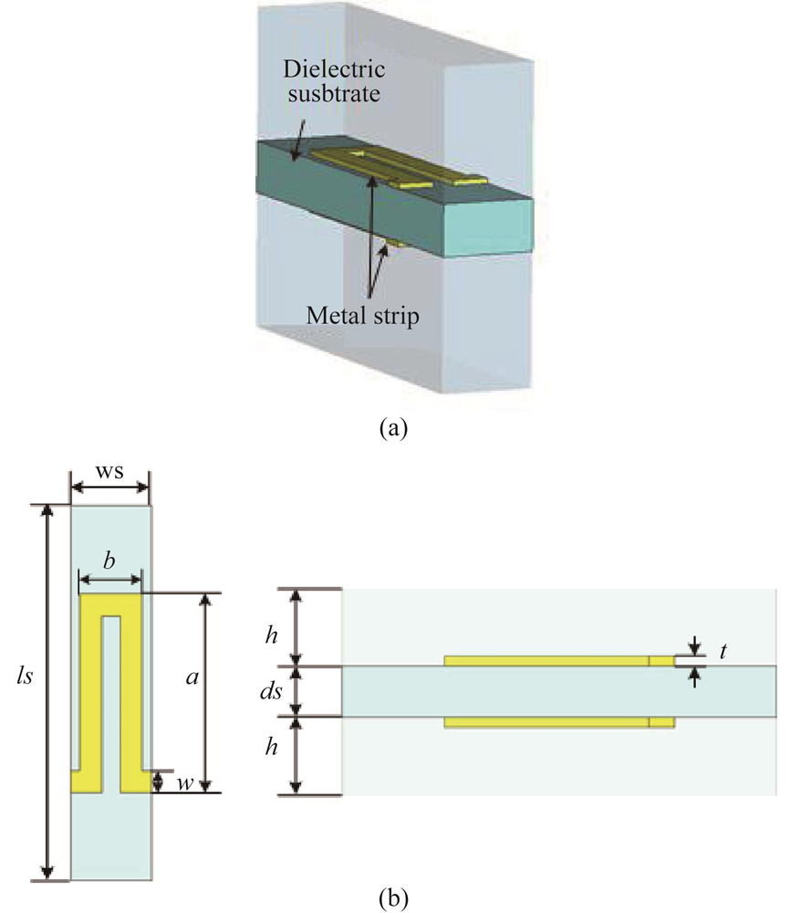
    Fig. 1. (a)The diagram unit model of the SDMML SWS,and (b) size view
    The electric field of (a) the odd mode, and (b) the even mode
    Fig. 2. The electric field of (a) the odd mode, and (b) the even mode
    The dispersion curves of the SDMML SWS
    Fig. 3. The dispersion curves of the SDMML SWS
    The interaction impedance curves of the odd mode of the SDMML SWS and conventional microstrip SWS
    Fig. 4. The interaction impedance curves of the odd mode of the SDMML SWS and conventional microstrip SWS
    (a) Output power, gain and (b) saturation power, gain curves of the SDMML SWSs with single and dual beam
    Fig. 5. (a) Output power, gain and (b) saturation power, gain curves of the SDMML SWSs with single and dual beam
    Electron bunching above the SDMML SWS
    Fig. 6. Electron bunching above the SDMML SWS
    Frequency spectrum of output signal(35 GHz)
    Fig. 7. Frequency spectrum of output signal(35 GHz)
    The model of the SDMML SWS with the input/output coupler
    Fig. 8. The model of the SDMML SWS with the input/output coupler
    The simulation transmission characteristics curves of the whole structure
    Fig. 9. The simulation transmission characteristics curves of the whole structure
    The SDMML SWS after laser processing (a) top view, (b) bottom view.
    Fig. 10. The SDMML SWS after laser processing (a) top view, (b) bottom view.
    The cold testing tube model and the pictures of the SDMML SWS and test tube
    Fig. 11. The cold testing tube model and the pictures of the SDMML SWS and test tube
    The cold testing result of the SDMML SWS
    Fig. 12. The cold testing result of the SDMML SWS
    (a) Diagram of oxidation area of the copper layer processed by laser, and (b) the model of oxidation area in simulation
    Fig. 13. (a) Diagram of oxidation area of the copper layer processed by laser, and (b) the model of oxidation area in simulation
    The comparison of transmission loss S21 of experiment and some kind of simulated models
    Fig. 14. The comparison of transmission loss S21 of experiment and some kind of simulated models
    ParametersValueParametersValue
    a/mm0.8w/mm0.1
    b0.184h/mm0.5
    t/mm0.01ls/mm1.6
    ws/mm0.368ds/mm0.2
    Table 1. Dimensional parameters of the designed SWS
    Operating parametersValueOperating parametersValue
    Voltage2050 VBeam-SWS distance0.05 mm
    Current0.1 A*2Focusing magnetic field0.2 T
    Cathode size0.8 mm*0.2 mmInput signal power50 mW
    Table 2. The operating parameters for hot performance simulation
    Teng-Long HE, Shao-Meng WANG, Xin-Yi LI, Duo XU, He-Xin WANG, Ning-Jie SHI, Hua-Rong GONG, Zhi-Gang LU, Zhan-Liang WANG, Zhao-Yun DUAN, Yu-Bin GONG. Design and test of a low voltage suspended dual-microstrip meander-line slow wave structure at Ka band[J]. Journal of Infrared and Millimeter Waves, 2022, 41(2): 437
    Download Citation