
Yilin Chen, Fayu Wang, Jianyang Liu. Non-Contact Portable Three-Dimensional Palmprint Acquisition System Based on Binocular Stereo Vision and Structured Light[J]. Laser & Optoelectronics Progress, 2022, 59(4): 0410016
- Laser & Optoelectronics Progress
- Vol. 59, Issue 4, 0410016 (2022)
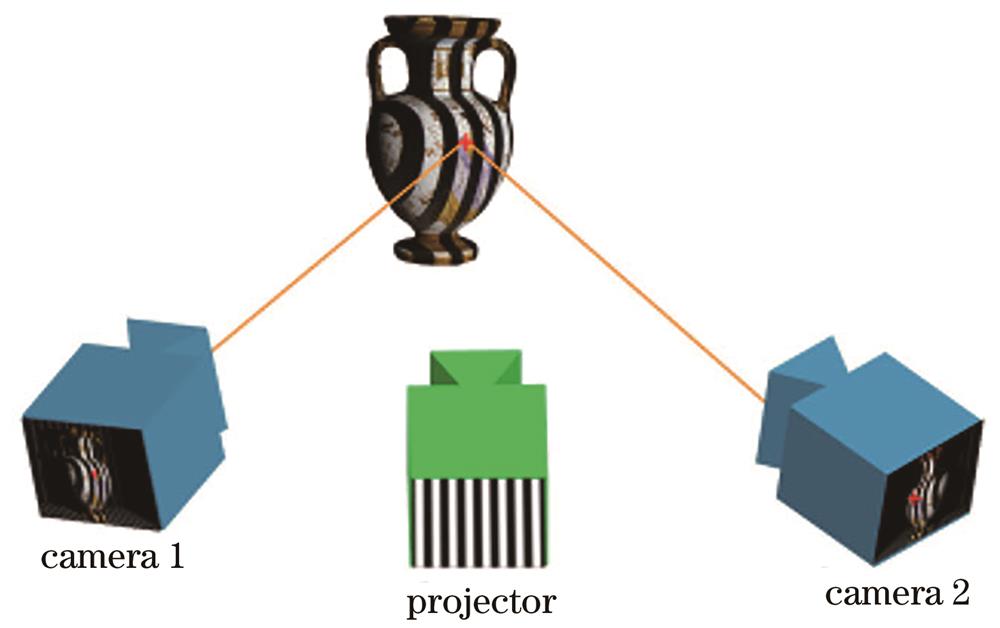
Fig. 1. Structure of binocular structured light system
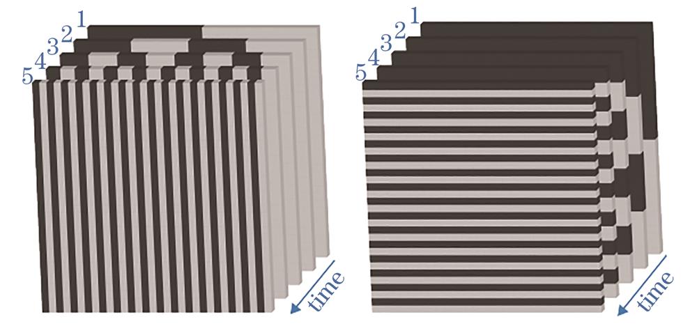
Fig. 2. Vertical and horizontal Gray-coded patterns
Fig. 3. 3D reconstruction results obtained by using single Gray code. (a) Using 10 Gray-code pictures; (b) using 9 Gray-code pictures; (c) using 8 Gray-code pictures
Fig. 4. Gray code assisted phase unwrapping
Fig. 5. Disparity maps of periodic jump correction. (a) Image before correction; (b) corrected image by traditional method; (c) corrected image by maximum probability method
Fig. 6. Linear interpolation diagram of right view pixels
Fig. 7. Point cloud effect comparison. (a) Pixel-level matching; (b) sub-pixel-level matching
Fig. 8. Comparison of palm surface reconstruction effects. (a) Using pixel-level matching; (b) using sub-pixel-level matching
Fig. 9. 3D palmprint acquisition system
Fig. 10. Calibration error of stereo camera
Fig. 11. Projected patterns
Fig. 12. Images obtained by left and right cameras before correction. (a) Left camera; (b) right camera
Fig. 13. Images obtained by left and right cameras after correction. (a) Left camera; (b) right camera
Fig. 14. Gray code phase shift decoding results of image taken by left camera. (a) Shadow area; (b) relative phase; (c) period; (d) absolute phase
Fig. 15. Disparity map
Fig. 16. Three-dimensional point cloud
Fig. 17. Point cloud filtering results. (a) Before point cloud filtering; (b) after point cloud filtering
Fig. 18. Reconstruction result of palm surface
Fig. 19. Images collected by 3D palmprint system based on stereo binocular camera. (a) Left view; (b) right view
Fig. 20. Comparison of experimental disparity maps. (a) Disparity map generated by traditional binocular stereo vision palmprint acquisition system; (b) disparity map generated by palmprint acquisition system proposed in this article

Set citation alerts for the article
Please enter your email address
© Copyright 2018-2021 | Chinese Laser Press. All Rights Reserved 沪ICP备15018463号-20