Hyeon-Hye Yu, Sunjae Gwak, Jinhyeok Ryu, Hyundong Kim, Ji-Hwan Kim, Jung-Wan Ryu, Chil-Min Kim, Chang-Hwan Yi, "Impact of non-Hermitian mode interaction on inter-cavity light transfer," Photonics Res. 10, 1232 (2022)

Search by keywords or author
- Photonics Research
- Vol. 10, Issue 5, 1232 (2022)

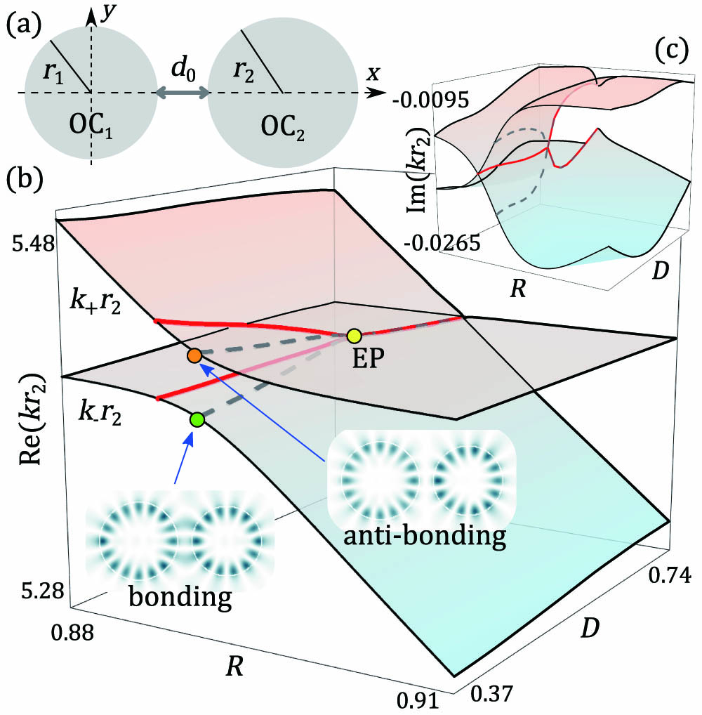
Fig. 1. (a) System configuration of coupled microcavities, where r 1 and r 2 are radii of cavities and d 0 is the inter-cavity distance. (b) and (c) are the Riemann surfaces for the real and imaginary parts of the resonant wavenumbers in the parameter space ( R , D ) , obtained using the boundary element method. The branch-cut (interaction center) is marked by a red solid (gray dashed) curve. The insets in (b) are the spatial distributions of the two coupled modes at the interaction center.

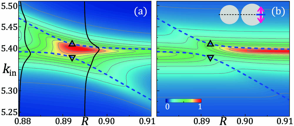
Fig. 2. (a) FDTD results of the EDA spectra of | a 1 | and (b) of | a 2 | at D = 0.37 , as a function of ( k in , R ) . The dashed curves are Re ( k ± r 2 ) obtained using the BEM. In (a), solid curves represent EDA as a function of k in for fixed R = 0.88 and 0.892, whereas the upper/lower triangles mark the anti-bonding/bonding modes. The inset in (b) shows the radiating pumping source (arrow) used in FDTD simulation.

Fig. 3. Couplings of WGM 1 and WGM 2 : (a) real and (b) imaginary parts of μ 12 r 2 (red circle) and μ 21 r 2 (black square) obtained using Eq. (6 ), as a function of R at D = 0.37 . In (c), Im ( K ± r 2 ) obtained using the BEM (gray solid) are compared to those obtained using Eq. (4 ) with the Hermitian (open circle) and non-Hermitian (red dashed line) couplings. The inset in (c) shows the Re ( K ± r 2 ) , where K ± r 2 are the re-expressed relative eigenvalues of the mean eigenvalues. The vertical solid lines in (c) and the inset mark the interaction center, whereas the vertical dashed line in (c) marks the branch-cut.

Fig. 4. TCMT results of the EDA spectra of | a 1 | with (a) true non-Hermitian and (b) artificial Hermitian couplings, respectively, at D = 0.37 . The insets show the values of | a 2 | . The dashed curves are Re ( k ± r 2 ) obtained using the BEM.
![(a) Parameter trajectory for the branch-cut (filled symbols) and the interaction center (open circles) for five cases of WGM coupling pairs defined by angular mode numbers: [(i), (m1,m2)=(4,5)], [(ii), (7,8)], [(iii), (11,12)], [(iv), (12,13)], [(v), (13,14)]. (b) |Im(⟨μ12μ21⟩)|r22 for pairs (i), (ii), and (v) obtained at D=0.37. (c) Comparison between the mean values of Im(kr2) and μij for the same pairs at D=0.37.](/Images/icon/loading.gif)
Fig. 5. (a) Parameter trajectory for the branch-cut (filled symbols) and the interaction center (open circles) for five cases of WGM coupling pairs defined by angular mode numbers: [(i), ( m 1 , m 2 ) = ( 4,5 ) ], [(ii), (7,8)], [(iii), (11,12)], [(iv), (12,13)], [(v), (13,14)]. (b) | Im ( ⟨ μ 12 μ 21 ⟩ ) | r 2 2 for pairs (i), (ii), and (v) obtained at D = 0.37 . (c) Comparison between the mean values of Im ( k r 2 ) and μ i j for the same pairs at D = 0.37 .

Fig. 6. Couplings for pair ( m 1 , m 2 ) = ( 7,7 ) , R ≈ 1 . (a) Real and (b) imaginary parts of μ 12 r 2 (red circle) and μ 21 r 2 (black square) obtained using Eq. (6 ), as a function of R at D = 0.37 . The (c) real and (d) imaginary relative eigenvalues of K ± r 2 obtained using the BEM (gray solid) are compared to those obtained using Eq. (4 ) with the Hermitian (open circle) and non-Hermitian (red dashed) couplings. The vertical solid lines in (c) and (d) indicate the interaction center.

Set citation alerts for the article
Please enter your email address