• Laser & Optoelectronics Progress
  • Vol. 56, Issue 6, 060004 (2019)
Liang Ding1、2、*, Zhiyong Wu1, Yucong Gu1、2, Zechao Gao1、2, Jintian Hu1、2, and Shuang Ma1
Author Affiliations
  • 1 Changchun Institute of Optics, Fine Mechanics and Physics, Chinese Academy of Sciences, Changchun, Jilin 130033, China
  • 2 University of Chinese Academy of Sciences, Beijing 100049, China
  • show less
    DOI: 10.3788/LOP56.060004 Cite this Article Set citation alerts
    Liang Ding, Zhiyong Wu, Yucong Gu, Zechao Gao, Jintian Hu, Shuang Ma. Key Technologies of Wireless Laser and Radio Frequency Complementary Communication System[J]. Laser & Optoelectronics Progress, 2019, 56(6): 060004 Copy Citation Text show less
    Block diagram of FSO and RF complementary communication system
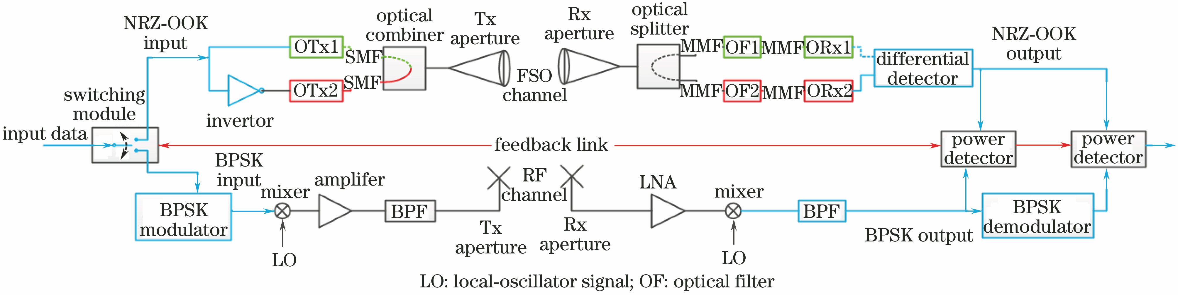
    Fig. 1. Block diagram of FSO and RF complementary communication system
    Schematic of hard switching
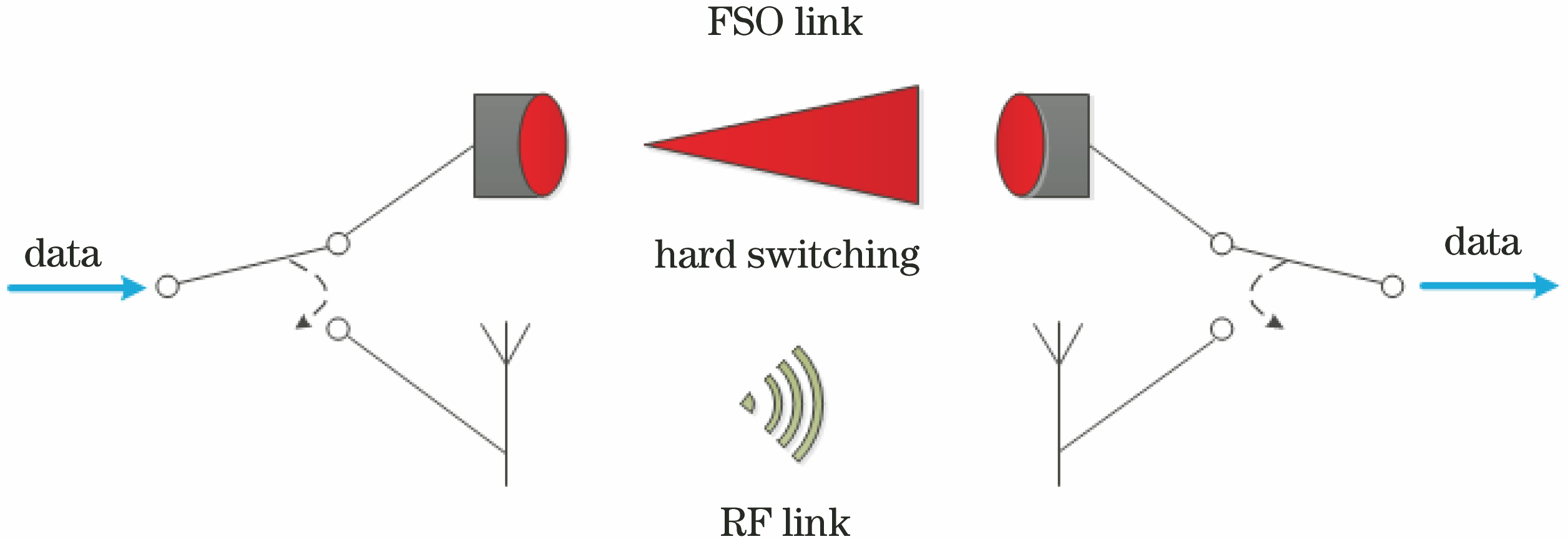
    Fig. 2. Schematic of hard switching
    Operation under dual FSO threshold
    Fig. 3. Operation under dual FSO threshold
    Operation regions under dual FSO threshold
    Fig. 4. Operation regions under dual FSO threshold
    Flow chart of time hysteresis algorithm
    Fig. 5. Flow chart of time hysteresis algorithm
    Flow chart of power hysteresis algorithm
    Fig. 6. Flow chart of power hysteresis algorithm
    Performance of trend prediction algorithm. (a) Reactive trend; (b) proactive trend
    Fig. 7. Performance of trend prediction algorithm. (a) Reactive trend; (b) proactive trend
    Block diagram of switching system based on RMS detector
    Fig. 8. Block diagram of switching system based on RMS detector
    Schematic of soft switching
    Fig. 9. Schematic of soft switching
    Soft-switching complementary communication system based on packet-level Raptor codes
    Fig. 10. Soft-switching complementary communication system based on packet-level Raptor codes
    Laser communication link with adaptive optics compensation
    Fig. 11. Laser communication link with adaptive optics compensation
    Structural diagram of optical modem
    Fig. 12. Structural diagram of optical modem
    Effect of OAGC on eye diagram of FSO link signal. (a) Without OAGC; (b) with OAGC
    Fig. 13. Effect of OAGC on eye diagram of FSO link signal. (a) Without OAGC; (b) with OAGC
    Block diagram of DFE
    Fig. 14. Block diagram of DFE
    System performances before and after equalization. (a) Before equalization; (b) after equalization
    Fig. 15. System performances before and after equalization. (a) Before equalization; (b) after equalization
    Improvement in SNR after adopting DFE. (a) Before equalization; (b) after equalization
    Fig. 16. Improvement in SNR after adopting DFE. (a) Before equalization; (b) after equalization
    Optical windows
    Fig. 17. Optical windows
    Link typeInstrumentParameterItem
    FSO linkData sourceModulation formatNRZ-OOK
    Data rate /(Mbit·s-1)10100
    Laser diodePeak wavelength /nm785
    Output power /mW3
    Beam divergence /mrad2
    Optical lensDiameter /mm40
    Focal length /mm100
    PhotodetectorModuleThorlabs PDA10A-EC
    Spectral range of sensitivity /nm200-1100
    Active area /mm20.8
    Typical spectral sensitivity /(A·W-1)0.45 at 750 nm
    RF linkModulation formatQPSK
    Carrier frequency /GHz2.4
    Bandwith /MHz10
    Transmitted RF power /dB-3
    Link span /m5.5
    Table 1. Key parameters of switching system based on RMS power detector
    ParameterSNRthresholdTime andpower delayTrendpredictionRMS powerdetectorPacket-levelRaptor codes
    Traffic rateMediumLowMediumLowHigh
    Bit error rateLowLowLowHighLow
    ReliabilityHighHighLow
    Channel resource utilizationLowLowLowLowHigh
    Decoding overheadLowLow
    Hardwareimplementation complexityHighLowLow
    Table 2. Characteristic analysis of main switching algorithms in complementary communication system
    Transmitter
    adaptive
    optics
    status
    Receiver
    adaptive
    optics
    status
    Measured
    PIB /dBm
    Measured
    PIF /dBm
    Transmitter
    correction
    distance /m
    Receiver
    correction
    distance /m
    Measured
    PIB /dBm
    Measured
    PIF /dBm
    OnOn0.0-10.04,9504,950-1.2-11.3
    OnOff-2.0-22.04,6000-5.9-20.9
    OffOn-12.0-23.007,900-9.0-27.1
    OffOff-12.5-00-12.5-34.0
    Table 3. Performance comparison of systems with and without adaptive optics compensation under strong turbulence( Cn2=1.45×10⁻¹⁴)
    Liang Ding, Zhiyong Wu, Yucong Gu, Zechao Gao, Jintian Hu, Shuang Ma. Key Technologies of Wireless Laser and Radio Frequency Complementary Communication System[J]. Laser & Optoelectronics Progress, 2019, 56(6): 060004
    Download Citation