Abstract
We report the generation of high energy 2 μm picosecond pulses from a thulium-doped fiber master oscillator power amplifier system. The all-fiber configuration was realized by a flexible large-mode area photonic crystal fiber (LMA-PCF). The amplifier output is a linearly-polarized 1.5 ns, 100 kHz pulse train with a pulse energy of up to 250 μJ. Pulse compression was achieved with (2+2)-pass chirped volume Bragg grating (CVBG) to obtain a 2.8 ps pulse width with a total pulse energy of 46 μJ. The overall system compactness was enabled by the all-fiber amplifier design and the multi-pass CVBG-based compressor. The laser output was then used to demonstrate high-speed direct-writing capability on a temperature-sensitive biomaterial to change its topography (i.e. fabricate microchannels, foams and pores). The topographical modifications of biomaterials are known to influence cell behavior and fate which is potentially useful in many cell and tissue engineering applications.Introduction
High power light sources emitting at 2 μm are useful for applications in the processing of semiconductors, clear polymers, and water-rich biological tissues and biomaterials1-3. Fiber lasers are particularly attractive as 2 μm sources offering excellent beam quality. Heat dissipation along long fiber lengths is efficient which enables high output powers. However, amplification of pulses with high peak power in fiber laser systems is limited by nonlinear effects due to the small mode field area (MFA). Increasing the fiber core size will effectively increase the MFA but the number of supported waveguiding modes increase as well, leading to beam quality degradation. To circumvent the small MFA limitation whilst preserving the single-mode guidance property, more sophisticated microstructured fibers were devised to substitute conventional step-index fiber designs4.
An increase in MFA supports higher peak powers, but amplification of pulse energies to hundreds of microjoule remains difficult due to the intrinsic peak power damage thresholds in silica. For amplification at high pulse energies, the chirped pulse amplification (CPA) technique can be exploited5. In CPA, the original pulse is stretched in time by a few orders of magnitude. The stretched pulse has a reduced peak power allowing amplification at intensities below the material damage threshold in the fiber. Recently, there have been demonstrations of thulium-based CPA systems with a record average power of more than 1 kW average power and peak power of more than 5 GW, without nonlinear compression6, 7. Such systems typically consist of a main amplifier gain fiber between a diffraction grating-based stretcher and compressor. The use of bulk optics and gratings necessitates free-space propagation and alignment, which offsets the compactness of fiber laser systems. Using a fiber-based dispersion compensation element for instance chirped fiber Bragg grating (CFBG) reduces the footprint of fiber CPA systems. However, a high peak power after amplification restricts the use of CFBGs as compressors. The use of gratings as compressors requires precise alignment and good grating quality to achieve excellent efficiency, pulse width, and beam quality. Alternatively, chirped volume Bragg gratings (CVBG) have been used as compressors for low input pulse energies (tens of μJ) in the 2 μm wavelength regime, in a simple configuration8.
In this paper, we present a fiber master oscillator power amplifier (MOPA) system which consists of an all-fiber amplifier and a compact multi-pass CVBG-based compressor. The main amplifier exploits CPA in a thulium-doped large-mode area photonic crystal fiber (TD-LMA-PCF) with an MFA of more than 1000 μm2. The all-fiber configuration was realized by splicing the TD-LMA-PCF to a conventional 30/250 polarization-maintaining (PM) fiber. The amplifier output is a linearly-polarized nanosecond pulse train with up to 25 W of average power corresponding to a peak power of 166 kW at 100 kHz pulse repetition rate. The nanosecond pulses were then re-compressed using a pair of CVBGs through a compact multi-pass configuration to 2.8 ps full-width at half-maximum with an output pulse energy of up to 46.3 μJ. To the best of our knowledge, this is the highest pulse energy handling using CVBGs at the 2 μm wavelength regime. The multi-pass compressor demonstrates compactness whilst allowing high input pulse energies (up to 150 μJ) and high stretching/compression ratios. The high-energy picosecond output was then used to demonstrate the high-speed direct-writing capability on a temperature-sensitive biomaterial for topological engineering of microchannels, foam structures and pores. These topographical changes on cell growth substrates have the potential to influence cell behavior and fate, and are useful in cell therapy, tissue engineering, and regenerative medicine work.
Methodology
Fiber MOPA system
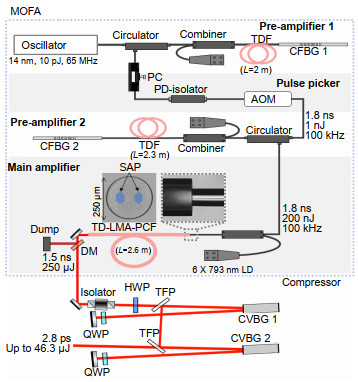
The all-fiber amplifier and the compact multi-pass compressor are depicted in Fig. 1. A compact oscillator, modified from our previous work9, outputs approximately 10 pJ seed pulses with a 14.5 nm spectral bandwidth at 1980 nm central wavelength, with a repetition rate of 65 MHz. The pulse duration could not be measured as the oscillator output power is too low (sub-milliwatt), but it is estimated to be sub-picosecond as the oscillator is operating in the soliton regime with a net cavity dispersion of -0.038 ps2. The oscillator pulses were amplified to 15 nJ through a cladding-pumped 10/130 double-clad thulium-doped fiber (TDF) and chirped to around 1 ns by CFBG 1 (D = -100 ps/nm) in Pre-amplifier 1. The lengths of the TDFs were chosen to have a total absorption of 13 dB at the pump wavelength.

Figure 1.Schematic of the system with the microscopy image of the thulium-doped large-mode area photonic crystal fiber (TD-LMA-PCF) cross-section and the splice point between the TD-LMA-PCF to a polarization-maintaining 30/250 silica fiber.
A polarization controller (PC) and polarization-dependent (PD) isolator function together as a Lyot filter10, allowing spectral and temporal shaping of the chirped nanosecond pulses. The PC was adjusted to induce more losses in the longer wavelengths, to compensate for the lower amplification in the shorter wavelengths, thus reducing the spectral narrowing effects later. At the same time, the filtering effect achieves 1.8 ns pulses as monitored by a photodetector. The fiber-pigtailed acousto-optic modulator (AOM) and its driver coupled with a digital divider/delay unit (DDU) function as the Pulse Picker to produce a 100 kHz pulse train from the original 65 MHz pulse train. Part of the oscillator output was detected by a photodiode to be used as the trigger for the DDU. The DDU is configured to gate 1 pulse for every 650 pulses, and outputs a radio frequency signal to the AOM driver, which drives the AOM to reduce the repetition rate from 65 MHz to 100 kHz.
Due to the high insertion loss of the AOM (7 dB), the pulse energy after the AOM is about 1 nJ. The 100 kHz pulse train with 1 nJ pulse energy is further amplified in a double-pass pre-amplifier (Pre-amplifier 2) to 200 nJ through a 2.3-metre long cladding-pumped PM TDF and CFBG 2 (D = +8.3 ps/nm). CFBG 2 serves as a reflector with a high reflectivity of 99% with a spectral bandwidth of 30 nm at 1975 nm central wavelength. The dispersion of CFBG 2 is low as compared to CFBG 1, and thus does not affect the pulse duration of the stretched nanosecond pulse. CFBG 2 also reduces the out-of-band amplified spontaneous emission (ASE) from propagating to the next stage by spectral filtering. The 100 kHz pulse train was further amplified through a 2.57-metre long TD-LMA-PCF with a 0.04 NA, 50-μm core diameter (mode field diameter of 37±3 μm), and a 250 μm inner cladding diameter. Its single-mode PM guidance enables better output stability and quality without tight coiling. As tight coiling is not required to induce losses for the higher-order modes, coiling-induced loss and mode area compression effects were eliminated. Furthermore, the multimode pump core with an air cladding has a large NA of > 0.5, which matches well with conventional double-cladding fibers for low-loss coupling of pump light. The TD-LMA-PCF is cladding-pumped by 6 fiber-pigtailed 793 nm laser diodes with a total output of up to 180 W, using a (6+1)×1 PM-combiner. The all-fiber amplifier was realized by splicing the TD-LMA-PCF to the 30/250 PM fiber (0.06 NA) of the combiner, and the splice point is shown in Fig. 1. The splicing was optimized to minimize loss and maximize both pump and signal transmission, whilst making sure the stress-applying parts (SAP) of the TD-LMA-PCF is aligned to that of the 30/250 PM fiber. The airholes of the TD-LMA-PCF were collapsed up to approximately 250 μm from the end facet to prevent contamination as seen in the splice point image in Fig. 1. Any further collapsing will induce high losses at the splice point due to the distortion of the fiber structure resulting in failure at high power operations. The entire TD-LMA-PCF was water cooled continuously at 12 ℃ inside a flexible and transparent tube. The output end has an angle-cleaved end cap, which increases the beam size at the output facet, reducing the chance of optical damage at high powers. A long-pass dichroic mirror (DM) was used to filter unabsorbed pump light. A high-power free-space isolator was also placed after the dichroic mirror to prevent back-reflection into the main amplifier.
The compressor consists of a pair of CVBGs (D = +22.8 ps/nm) in a compact multi-pass configuration to re-compress the chirped nanosecond pulses. The CVBG's central Bragg wavelength is 1977.5 nm with a bandwidth of 36 nm. The large aperture, 5 mm (vertical) × 10 mm (horizontal), allows a large beam input diameter and consequently enables high pulse energy handling. The CVBGs were mounted on water-cooled copper blocks continuously kept at 20 ℃. The multi-pass configuration was realized by directing the beam into each CVBG with a small angle of incidence using a series of half waveplate (HWP), quarter waveplates (QWP), thin-film polarizers (TFP), and mirrors as shown in Fig. 1.
Topographical engineering of biomaterial
A laser scanner system was set up which consists of an X-Y scanner (scanning speeds of up to 1000 mm/s) and a telecentric f-theta lens (focal length of 28 mm) as shown in Fig. 2. The X-Y scanner is connected to a computer installed with software to control the scanner movements. Simple patterns can be drawn directly, or computer-assisted drawing files may be imported into the software. The laser output power was set at the maximum 4.6 W average power, corresponding to 46 μJ pulse energy at 100 kHz repetition rate. A waveplate and polarizer was placed before the X-Y scanner to control the amount of power that will be used. The spot size (1/e2) was measured to be 201 μm by 131 μm using a beam profiler camera at the focal plane after the f-theta lens.
Figure 2.Schematic of laser scanner setup for the topographical engineering of hydrogels.
Two types of samples were prepared for the demonstration of topographical engineering of biomaterials using the fiber laser. The first type was hydrogels (0.4% agarose + 0.25% gelatin), prepared using a protocol used in cell culture studies11. The second type of sample was dried films prepared from the same hydrogels as before which were then left to dry in a vacuum oven. The thickness of the films was measured to be approximately 120 μm. The samples were set in a typical plastic petri dish and placed on a stage during the laser processing.
Results and discussion
Fiber laser performance and discussion
The maximum output power from the all-fiber amplifier was 25 W which corresponds to a pulse energy of 250 μJ with a 21% slope efficiency at 100 kHz repetition rate as shown in Fig. 3(a). The beam profiles at various output powers are depicted in Fig. 3(b). The pulse duration was measured to be 1.5 ns using a fast 12.5 GHz photodetector (EOT ET-5000F), corresponding to a peak power of 166 kW at 25 W. The output peak power was limited by the prevalence of nonlinear effects in the main amplifier. Particularly for the 2-μm waveband in silica, modulation instability (MI) and four-wave mixing (FWM) occur at high peak powers12. The output spectra are shown in Fig. 3(c) and the 10-dB bandwidth at 4 W, 15 W and 25 W are 29 nm, 36 nm and 53 nm, respectively. The polarization extinction ratio (PER) measured at the PCF output was at least 11 dB at output powers between 1 and 25 W.
Figure 3.(a) Slope efficiency curve of the main amplifier; (b) TD-LMA-PCF beam profile at different output powers; (c) Spectra of main amplifier seed (pre-amplifier 2 output) and main amplifier output at different pulse energies. Inset: Main amplifier output pulse measured using a fast photodetector.
The transmission of the high-power free-space isolator before the compressor was measured to be 81.65±1.50% from 1 W to 25 W output powers. After the isolator and undergoing 4 passes through the CVBG pair, the final output had a maximum average power of 4.63 W from the initial main amplifier output of 15 W. The final compressor output of 4.63 W corresponds to a pulse energy of 46.3 μJ at 100 kHz repetition rate. To the best of our knowledge, this is the highest output pulse energy from a CVBG-based compressor at the 2 μm wavelength regime.
The output power from the main amplifier to the compressor stage was limited at 15 W due to excessive losses at the first CVBG. The limited transmission bandwidth of the CVBGs acts as a spectral filter, allowing the out-of-band light to leak from the back of the CVBG as transmission. Thus, the main amplifier output with wavelengths below 1959 nm and above 1995 nm were not reflected by the CVBGs. The leakage from CVBG 1 was measured to be 1.7% of the main amplifier output at 2 W output power, which increased progressively as shown in Fig. 4(a), up to 47% when the output power was 25 W. Hence, we limited the main amplifier output power to the compressor at 15 W before the leakage from CVBG 1 rises steeply. Excluding the loss contributed by the isolator, the 4-pass compressor efficiency is up to 51.2% at 4 W, before decreasing to 38.1% at 15 W average powers of the main amplifier output. The decrease in compressor efficiency was found to correspond to the increase in leakage from CVBG 1 as shown in Fig. 4(a).
Figure 4.(a) Compressor efficiency and CVBG 1 leakage at different main amplifier output powers; (b) Autocorrelation trace of recompressed pulse at 1.7 W and 4.6 W average powers. Inset: Spectra at corresponding output powers after the compressor.
The PER after the 4-pass compressor was at least 26 dB at all powers measured. The second-harmonic autocorrelation measurement of the dechirped pulses at 1.7 W and 4.6 W, corresponding to 17 μJ and 46 μJ pulse energies respectively, are shown in Fig. 4(b). At 17 μJ and 46 μJ pulse energies, the full-width at half-maximum are 5.5 ps and 3.9 ps, corresponding to a pulse duration of 3.9 ps and 2.8 ps respectively based on the Gaussian pulse shape assumption. The compressor output spectra were collected after attenuation through a waveplate and polarizer before being focused into a multi-mode silica fiber to the optical spectrum analyzer. The compressor output spectra are shown in the inset of Fig. 4(b). The output spectra were clipped due to the CVBG's spectral bandwidth. The dip around 1975 nm was due to spatial chirp of the beam, thus some of the spectral components were not collected by the silica fiber for the spectral measurement.
From the autocorrelation trace, the pulse width is not transform-limited and there are pedestal features even at low pulse energies. Looking at the spectral profile of the chirped seed pulse, there are modulations which correspond to amplitude modulations in the temporal domain. This in turn causes Kerr-induced temporal phase oscillations during amplification in the main amplifier13. The CVBG-based compressor, which is designed to compensate linear chirp, is unable to compensate these phase oscillations14. Thus, some of the pulse energy was not confined within the main pulse after recompression. Furthermore, the B-integral value for the main amplifier was calculated to be about 5 rad at 150 μJ output pulse energies. The increased B-integral compounds to the nonlinear phase shift accumulated. Consequently, these nonlinear phase shifts may cause the pulse temporal profile to have more prominent side lobes and pedestal, shifting more energy away from the main pulse after recompression. On the other hand, these nonlinear phase shifts may have also contributed to a narrower pulse duration of 2.8 ps as compared to 3.9 ps after compression, at the expense of the stronger pulse distortions. The pedestals contain approximately 60% and 50% of the total pulse energy for the 2.8 ps pulse and the 3.9 ps pulse respectively, inferring a peak power of approximately 6.6 MW for the 2.8 ps pulse.
The beam quality after the 4-pass compressor was checked through an M2 measurement with a beam profiler camera at the highest output pulse energy according to the ISO 11146 compliant standard. The measurement which resulted in an M2 value of 1.5 and the collimated beam profile at the highest pulse energy are shown in Fig. 5(a). The power stability of the compressor output was also measured as shown in Fig. 5(b), and the power fluctuations were calculated to be 0.49% at 4.6 W average output power over the 2-hour duration. The stable output power over 2 hours demonstrates the stability of the overall system.
Figure 5.(a)M2 measurement at the highest pulse energy after compressor. Inset: Beam profile at the highest pulse energy after compressor; (b) Power stability of the compressor output over 2 hours.
In this work, the main amplifier slope efficiency was limited to 21%, due to the low seeding energy and repetition rate. Increasing the seeding energy by increasing the gain at the pre-amplifier stages would bring about undesirable nonlinear effects at 100 kHz repetition rate operation. Hence, we did not increase the seeding energy to the main amplifier. At the full 65 MHz repetition rate, the main amplifier slope efficiency improved to 39% at the expense of the pulse energy15.
We acknowledge the limitations of our work and propose these strategies to improve future work. The pulse energy and consequently, the peak power, were limited in this work due to nonlinear effects. The nonlinear effects in the main amplifier could be better mitigated by using a CFBG with a higher stretching factor, with a matching CVBG compressor. The spectral modulations from the pre-amplifier stages cause Kerr-induced phase modulations in the main amplifier, degrading the recompressed pulse temporal profile. These modulations may have originated from nonlinear effects in the pre-amplifier stages. In this work, the AOM introduced a large insertion loss (7 dB) necessitating high gains in the pre-amplifier stages to provide enough seeding energy to the main amplifier. Besides replacing the AOM, the phase modulations can be reduced by spectral amplitude shaping16, or by using gain fibers with normal dispersion made possible by recent developments in normal dispersion TDFs14, 17. Using normal dispersion TDFs in the CPA system would reduce the nonlinearity-induced spectral broadening and mitigate the decrease in compressor efficiency at high pulse energies when the pulse spectrum exceeded the CVBG bandwidth. Lastly, the pulse compression quality can be further improved by using a matched pair of tunable CFBG and CVBG18. The tunability of the 2nd, 3rd, and 4th-order dispersion of the CFBG allows dynamic pre-compensation of the high-order dispersion and nonlinear-induced phase shift. Unfortunately, these additional components were beyond our currently available resources.
Application on topographical engineering of hydrogels
The fiber laser was used to demonstrate biomaterial processing on hydrogels, a commonly used scaffold and substrate in cell culture studies. Hydrogels are cross-linked polymeric biomaterials with human tissue-like water content and physiochemical resemblance. Hence, they have been widely accepted as tissue analogs in cell therapy, tissue engineering and regenerative medicine research19, 20.
The topography and chemical composition of the substrate affect cell behaviour and proliferation, rendering the manipulation of substrate properties important in cell and tissue engineering applications21-25. Topographical properties such as porosity, surface roughness, micro- and macro-patterns influence cell adhesion, direct cell growth, and in some cases cell differentiation24, 26, 27.
Topographical manipulation of biomaterials can be done using various techniques such as 3D-printing, lithography-based methods, and moulding28-32. The variable parameters include but are not limited to, nano-, micro- and macrostructures, porosity, and mechanical properties. Laser-based modification of biomaterials has gained popularity in recent years due to its high-resolution control and flexibility in altering the biomaterial simply by steering the laser beam and varying laser parameters such as fluence, and pulse duration33-35.
A wide range of materials can be laser-engineered, but some require modification to be photolabile to enhance laser-material interactions. The use of a 2 μm laser source eliminates the need for photolabile materials as most biomaterials are water-rich and can absorb at this wavelength strongly. This is advantageous as it also minimizes potential sources of contamination. Biomaterials such as gelatin-based gels typically have low melting temperatures of below 40 ℃ depending on concentration36. Thus, ultrafast lasers with short pulse durations are useful to process these temperature-sensitive materials, as less heat is produced as compared to long-pulse or CW lasers.
The highest scanning speed of 1000 mm/s and laser output power of 3 W were used to create microchannel structures with channel widths of approximately 25-30 μm on the hydrogels as shown in Fig. 6. Increasing the laser power or decreasing the scanning speed creates wider channels. The microchannels may be useful to contain cells, align cells such as cardiac and neuronal cells, or to direct the differentiation of stem cells into cardiac cells27, 37. The microchannels may also serve as perfusion channels to allow more efficient transport of waste and nutrients to the cells cultured on the hydrogels38, 39. Hence, the high speed direct-writing of the microchannels on hydrogels was demonstrated using the ultrafast 2um fiber CPA laser system, as shown in Fig. 7(a). The high-speed processing was enabled by the high pulse energy and high repetition rate and was limited by the X-Y scanner's scanning speed.
Figure 6.Microscopy image of microchannels abricated on the hydrogel.
Figure 7.(a) Schematic of laser scanner setup on dried hydrogel films. Inset: Schematic of foam formation due to water absorption within film causing laser-induced expansion. (b) Scanning electron microscopy images of foamed hydrogel films with decreasing photon flux (scanning speeds of 100, 120 and 150 mm/s at 4 W) from left to right.
The effect of the 2 μm laser source on dried hydrogel films was then investigated. The films were prepared from the same hydrogels as before and were then left to dry in a vacuum oven set at 40 ℃ for 16 hours. Opaque white foam was observed on the film surface after laser processing at scanning speeds of 100 to 150 mm/s and at the laser output power of 4 W. The mechanism of the foam formation is laser-induced expansion due to explosive ablation40, 41. The hydrogel films still contain some moisture after drying42, 43, and these water molecules within the film absorb 2 μm strongly. The high energy fluence at the focal plane and strong water absorption causes the hydrogel film to expand thus creating the foam structure.
It was observed that the photon flux controls the morphology of the foam on the hydrogel films. Photon flux was varied by controlling the scanning speed and line spacing. At a low scanning speed (100 mm/s) and line spacing of 100 μm, the photon flux is higher, and the formation of pores was observed. Decreased photon flux resulted in foam formation without pores and increased smoothness as shown in Fig. 7(b). Several studies have found that foams increase cell adhesion sites and different cell types grow optimally in certain range of pore sizes44, 45. Additionally, the foam structure has increased porosity which improves fluid permeability, thus facilitating oxygen and nutrient exchange aiding in cell growth46, 47.
Conclusions
In conclusion, we report on the generation of high-energy megawatt-level picosecond pulses at a 100 kHz repetition rate from a compact thulium-based fiber MOPA system. The chirped output from the all-fiber amplifier is a linearly polarized nanosecond pulse train with up to 25 W average power corresponding to pulse energies of 250 μJ with a PER of > 11 dB. The high-energy output was realized using a TD-LMA-PCF with an MFA of more than 1000 μm2 as the main amplifier gain fiber. The all-fiber configuration was enabled by optimizing the splice point between the TD-LMA-PCF to a 250-μm PM silica fiber. We further devised a compact (450 mm by 450 mm footprint) compressor using a 4-pass CVBG configuration. Through the compressor, we obtained a 2.8 ps pulse duration with a total pulse energy of 46 μJ, despite high device losses. To the best of our knowledge, this is the highest output pulse energy from a CVBG-based compressor at 2 μm wavelengths. The high-energy picosecond output was then used for high-speed direct-writing on a temperature-sensitive biomaterial, for topographical engineering to create microchannels, foam structures and pores. The fabricated morphology was controlled by simply steering the beam and varying the laser parameters. The topographical modification of hydrogels influence cell adhesion, cell alignment, facilitate cell-cell interactions and hence directing cell growth which will be useful in cell therapy, tissue engineering, and regenerative medicine applications.
Acknowledgements
This work was supported by Agency for Science, Technology and Research (A*STAR), Singapore through the X-ray Photonics Programme (1426500052) and A*STAR Graduate Academy through the A*STAR Graduate Scholarship. The authors would like to thank Ahmad Amirul and Clarice Loke for their assistance with the scanning electron microscopy images.
Author contributions
All authors reviewed and revised the manuscript with valuable suggestions. E. Lee, B. Sun and J. Luo performed the fiber laser experiments, the measurements and analysis. E. Lee and D. Yong designed and initiated the hydrogel processing project. S. Singh assisted in sample preparations and discussions. X. Yu and Q. J. Wang provided the initial fiber laser project direction, designed and initiated the fiber laser project.
Competing interests
The authors declare no competing financial interests.
References
[1] N Gehlich, T Bonhoff, L Sisken, M Ramme, C Gaida et al. Utilizing the transparency of semiconductors via "backside" machining with a nanosecond 2 μm Tm:fiber laser. Proc SPIE, 8968, 89680W(2014).
[2] B Voisiat, D Gaponov, P Gečys, L Lavoute, M Silva et al. Material processing with ultra-short pulse lasers working in 2μm wavelength range. Proc SPIE, 9350, 935014(2015).
[3] R L Blackmon, N M Fried, P B Irby. Comparison of holmium:YAG and thulium fiber laser lithotripsy: ablation thresholds, ablation rates, and retropulsion effects. J Biomed Opt, 16, 071403(2011).
[4] F Jansen, F Stutzki, C Jauregui, J Limpert, A Tünnermann. High-power very large mode-area thulium-doped fiber laser. Opt Lett, 37, 4546-4548(2012).
[5] P Maine, D Strickland, P Bado, M Pessot, G Mourou. Generation of ultrahigh peak power pulses by chirped pulse amplification. IEEE J Quantum Electron, 24, 398-403(1988).
[6] C Gaida, M Gebhardt, T Heuermann, F Stutzki, C Jauregui et al. Ultrafast thulium fiber laser system emitting more than 1 kW of average power. Opt Lett, 43, 5853-5856(2018).
[7] C Gaida, M Gebhardt, F Stutzki, C Jauregui, J Limpert et al. 90 fs pulses with> 5 GW peak power from a high repetition rate Tm-doped fiber CPA system. In Advanced Solid State Lasers 2017 (Optical Society of America, 2017)(2017).
[8] D Gaponov, L Lavoute, N Ducros, A Hideur, S Février et al. 10 μJ-Class compact thulium all-fibered CPA system. In 2017 Conference on Lasers and Electro-Optics Europe and European Quantum Electronics Conference (Optical Society of America, 2017)(2017).
[9] J Q Luo, B Sun, J H Ji, E L Tan, Y Zhang et al. High-efficiency femtosecond Raman soliton generation with a tunable wavelength beyond 2μm. Opt Lett, 42, 1568-1571(2017).
[10] B Lyot. Optical apparatus with wide field using interference of polarized light. C R Acad Sci, 197, 1593(1933).
[11] R Imani, S H Emami, P R Moshtagh, N Baheiraei, A M Sharifi. Preparation and characterization of agarose-gelatin blend hydrogels as a cell encapsulation matrix: an in-vitro study. J Macromol Sci, Part B, 51, 1606-1616(2012).
[12] A Sincore, J D Bradford, J Cook, L Shah, M C Richardson. High average power thulium-doped silica fiber lasers: review of systems and concepts. IEEE J Sel Top Quantum Electron, 24, 0901808(2018).
[13] D N Schimpf, E Seise, J Limpert, A Tünnermann. Decrease of pulse-contrast in nonlinear chirped-pulse amplification systems due to high-frequency spectral phase ripples. Opt Express, 16, 8876-8886(2008).
[14] D N Schimpf, E Seise, J Limpert, A Tünnermann. Self-phase modulation compensated by positive dispersion in chirped-pulse systems. Opt Express, 17, 4997-5007(2009).
[15] E Lee, J Q Luo, B Sun, V Ramalingam, Y Zhang et al. Flexible single-mode delivery of a high-power 2μm pulsed laser using an antiresonant hollow-core fiber. Opt Lett, 43, 2732-2735(2018).
[16] D N Schimpf, J Limpert, A Tünnermann. Controlling the influence of SPM in fiber-based chirped-pulse amplification systems by using an actively shaped parabolic spectrum. Opt Express, 15, 16945-16953(2007).
[17] Y H Chen, S Raghuraman, D Ho, D Y Tang, S Yoo. Normal dispersion thulium fiber for ultrafast near-2 μm fiber laser. In 2018 Conference on Lasers and Electro-Optics: CLEO: Applications and Technology 2018 (Optical Society of America, 2018)(2018).
[18] T Bartulevicius, S Frankinas, A Michailovas, R Vasilyeu, V Smirnov et al. Compact fiber CPA system based on a CFBG stretcher and CVBG compressor with matched dispersion profile. Opt Express, 25, 19856-19862(2017).
[19] S Turunen, A M Haaparanta, R Äänismaa, M Kellomäki. Chemical and topographical patterning of hydrogels for neural cell guidance in vitro. J Tissue Eng Regen Med, 7, 253-270(2013).
[20] T Y Yu, C K Ober. Methods for the topographical patterning and patterned surface modification of hydrogels based on hydroxyethyl methacrylate. Biomacromolecules, 4, 1126-1131(2003).
[21] M Nikkhah, F Edalat, S Manoucheri, A Khademhosseini. Engineering microscale topographies to control the cell-substrate interface. Biomaterials, 33, 5230-5246(2012).
[22] H N Kim, A Jiao, N S Hwang, M S Kim, D H Kang et al. Nanotopography-guided tissue engineering and regenerative medicine. Adv Drug Deliv Rev, 65, 536-558(2013).
[23] M J Dalby, N Gadegaard, R O C Oreffo. Harnessing nanotopography and integrin-matrix interactions to influence stem cell fate. Nat Mater, 13, 558-569(2014).
[24] F Brandl, F Sommer, A Goepferich. Rational design of hydrogels for tissue engineering: impact of physical factors on cell behavior. Biomaterials, 28, 134-146(2007).
[25] K J Burg, S Porter, J F Kellam. Biomaterial developments for bone tissue engineering. Biomaterials, 21, 2347-2359(2000).
[26] A Ranella, M Barberoglou, S Bakogianni, C Fotakis, E Stratakis. Tuning cell adhesion by controlling the roughness and wettability of 3D micro/nano silicon structures. Acta Biomater, 6, 2711-2720(2010).
[27] C G Anene-Nzelu, D Choudhury, H P Li, A Fraiszudeen, K Y Peh et al. Scalable cell alignment on optical media substrates. Biomaterials, 34, 5078-5087(2013).
[28] D Falconnet, G Csucs, H M Grandin, M Textor. Surface engineering approaches to micropattern surfaces for cell-based assays. Biomaterials, 27, 3044-3063(2006).
[29] A A Chaudhari, K Vig, D R Baganizi, R Sahu, S Dixit et al. Future prospects for scaffolding methods and biomaterials in skin tissue engineering: a review. Int J Mol Sci, 17, 1974(2016).
[30] X H Liu, P X Ma. Polymeric scaffolds for bone tissue engineering. Ann Biomed Eng, 32, 477-486(2004).
[31] F Guillemot, A Souquet, S Catros, B Guillotin, J Lopez et al. High-throughput laser printing of cells and biomaterials for tissue engineering. Acta Biomater, 6, 2494-2500(2010).
[32] B Subia, J Kundu, S C Kundu. Biomaterial scaffold fabrication techniques for potential tissue engineering applications. Tissue Eng, 141(2010).
[33] D B Chrisey. The power of direct writing. Science, 289, 879-881(2000).
[34] K C Hribar, P Soman, J Warner, P Chung, S C Chen. Light-assisted direct-write of 3D functional biomaterials. Lab Chip, 14, 268-275(2014).
[35] P K Wu, B R Ringeisen, D B Krizman, C G Frondoza, M Brooks et al. Laser transfer of biomaterials: Matrix-assisted pulsed laser evaporation (MAPLE) and MAPLE Direct Write. Rev Sci Instrum, 74, 2546-2557(2003).
[36] F Johnston-Banks et al. Gelatine. Food Gels, 233-289(1990).
[37] A Tijore, S A Irvine, U Sarig, P Mhaisalkar, V Baisane et al. Contact guidance for cardiac tissue engineering using 3D bioprinted gelatin patterned hydrogel. Biofabrication, 10, 025003(2018).
[38] A Kobuszewska, E Tomecka, K Zukowski, E Jastrzebska, M Chudy et al. Heart-on-a-Chip: an investigation of the influence of static and perfusion conditions on cardiac (H9C2) cell proliferation, morphology, and alignment. SLAS Technol: Transl Life Sci Innov, 22, 536-546(2017).
[39] N Korin, A Bransky, M Khoury, U Dinnar, S Levenberg. Design of well and groove microchannel bioreactors for cell culture. Biotechnol Bioeng, 102, 1222-1230(2009).
[40] S Gaspard, M Oujja, C Abrusci, F Catalina, S Lazare et al. Laser induced foaming and chemical modifications of gelatine films. J Photochem Photobiol A: Chem, 193, 187-192(2008).
[41] S Lazare, V Tokarev, A Sionkowska, M Wiśniewski. Surface foaming of collagen, chitosan and other biopolymer films by KrF excimer laser ablation in the photomechanical regime. Appl Phys A, 81, 465-470(2005).
[42] R C Simoni, G F Lemes, S Fialho, O H Gonçalves, A M Gozzo et al. Effect of drying method on mechanical, thermal and water absorption properties of enzymatically crosslinked gelatin hydrogels. An Acad Bras Ciênc, 89, 745-755(2017).
[43] H Emoto, H Kambic, J F Chen, Y Nosé. Characterization of rehydrated gelatin gels. Artif Organs, 15, 29-34(1991).
[44] P Viswanathan, M G Ondeck, S Chirasatitsin, K Ngamkham, G C Reilly et al. 3D surface topology guides stem cell adhesion and differentiation. Biomaterials, 52, 140-147(2015).
[45] F J O'Brien, B A Harley, I V Yannas, L J Gibson. The effect of pore size on cell adhesion in collagen-GAG scaffolds. Biomaterials, 26, 433-441(2005).
[46] P Eiselt, J Yeh, R K Latvala, L D Shea, D J Mooney. Porous carriers for biomedical applications based on alginate hydrogels. Biomaterials, 21, 1921-1927(2000).
[47] T G Van Tienen, G J C Heijkants Ralf, P Buma, J H de Groot, A J Pennings et al. Tissue ingrowth and degradation of two biodegradable porous polymers with different porosities and pore sizes. Biomaterials, 23, 1731-1738(2002).