
Junwei Cheng, Zhenming He, Yuhao Guo, Bo Wu, Hailong Zhou, Teyan Chen, Yixin Wu, Wenwei Xu, Jianji Dong, Xinliang Zhang. Self-calibrating microring synapse with dual-wavelength synchronization[J]. Photonics Research, 2023, 11(2): 347
- Photonics Research
- Vol. 11, Issue 2, 347 (2023)
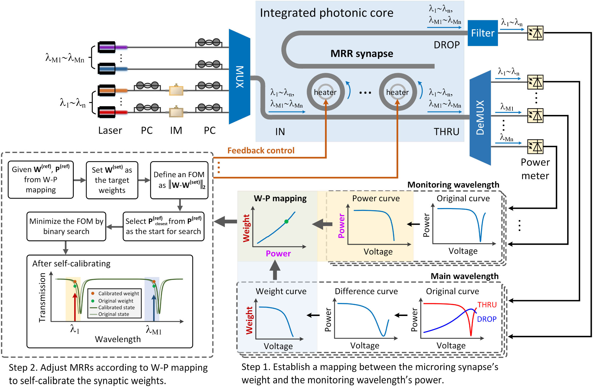
Fig. 1. Conceptual diagram of the self-calibrating microring synapse with dual-wavelength synchronization. Monitoring wavelengths are added to monitor and calibrate the synaptic weights, and a thermally insensitive mapping between the synaptic weights and monitoring wavelengths can be established to provide accurate initial reference points for the parameter update procedure.
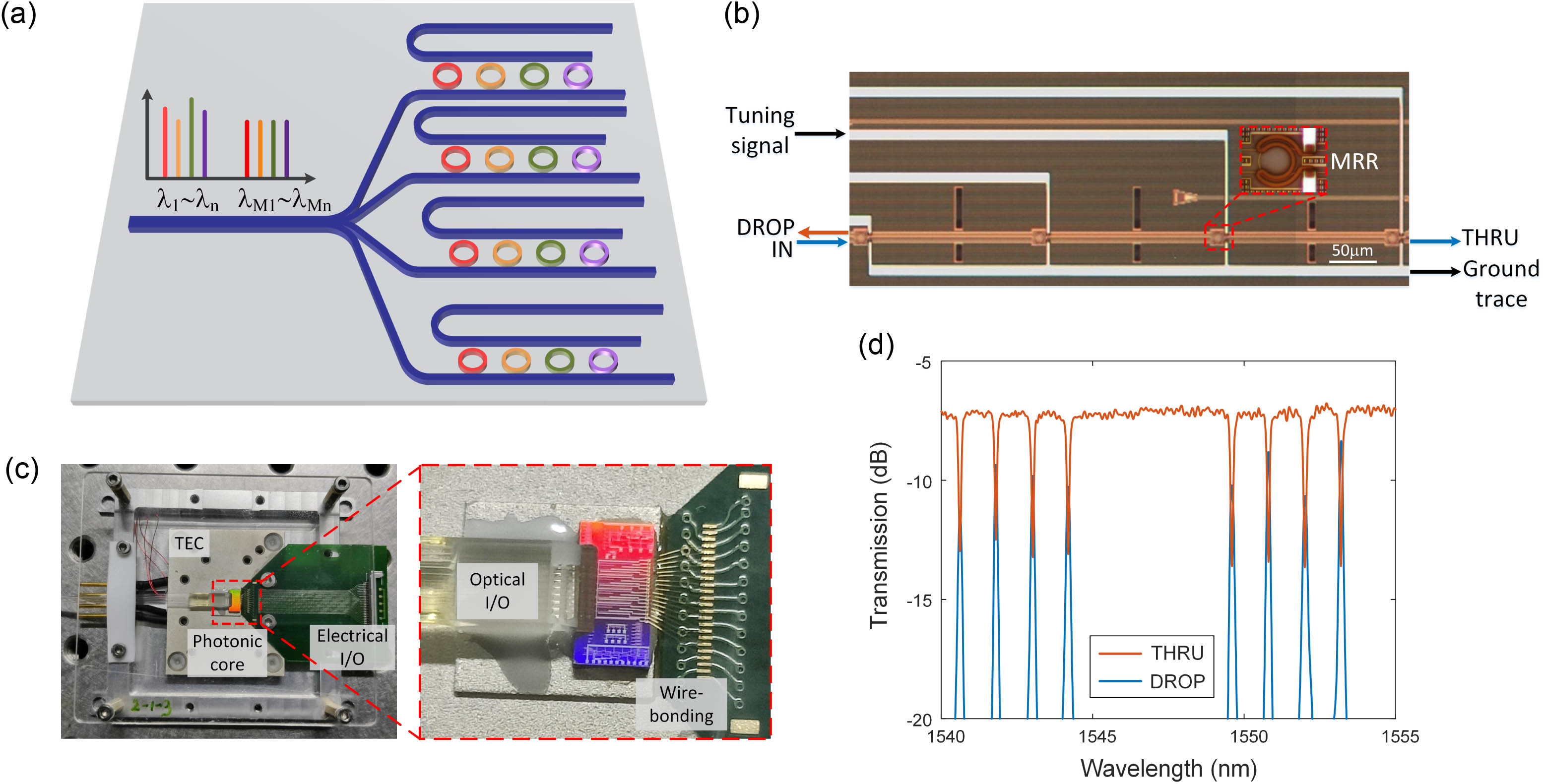
Fig. 2. Detailed design of the integrated microring synapse. (a) The schematic structure of the 4 × 4
Fig. 3. Comparison of the calibrated weights and theoretical weights of the individual MRR of the microring synapse.
Fig. 4. The calibration with dual-wavelength synchronization improves the precision of weighting in the two-MRR synapses. (a) The measurement of the weighting precision before the self-calibration. (b) The measurement of the weighting precision after the self-calibration. The weighting precision is evaluated at equally spaced weights on the heatmap. Each sub-square in the heatmap represents the weighting error of a measured weight, and its shade represents the magnitude of the error. (c) and (d) are the weighting error for the evaluation in (a) and (b), respectively, calculated as Δ w = w − w set w w set
Fig. 5. Robust performance of the self-calibrating microring synapse against environmental temperature fluctuations. The tested weights consist of positive, zero, and negative weights, including weight of (a) 0.3, (b) 0, (c) − 0.2 − 0.5
Fig. 6. Simulation results of Newton’s iterative method for matrix inversion tasks with bit precision of 4 bits, 5 bits, 6 bits, 7 bits, and 8 bits.
Fig. 7. Matrix inversion based on Newton’s iteration for two different initial matrices. (a) The implementation of an individual Newton’s iteration expressed by Eq. (3 ). (b) The theoretical and experimental results for the initial matrix A 1 A 1 A 2 A 2
|
Table 1. Comparison of Our Weight Monitoring Scheme with Three Mainstream Schemes

Set citation alerts for the article
Please enter your email address
© Copyright 2018-2021 | Chinese Laser Press. All Rights Reserved 沪ICP备15018463号-20