• Photonics Research
  • Vol. 11, Issue 2, 347 (2023)
Junwei Cheng1、2、†, Zhenming He1、2、†, Yuhao Guo3、†, Bo Wu1、2, Hailong Zhou1、2, Teyan Chen3, Yixin Wu3, Wenwei Xu4、5、*, Jianji Dong1、2、6、*, and Xinliang Zhang1、2
Author Affiliations
  • 1Wuhan National Laboratory for Optoelectronics, Huazhong University of Science and Technology, Wuhan 430074, China
  • 2Optics Valley Laboratory, Wuhan 430074, China
  • 3Galileo Advanced Technology Lab, Huawei Technologies, Shenzhen 518129, China
  • 4Institute of Strategic Research, Huawei Technologies, Shenzhen 518129, China
  • 5e-mail: xuwenwei@huawei.com
  • 6e-mail: jjdong@mail.hust.edu.cn
  • show less
    DOI: 10.1364/PRJ.478370 Cite this Article Set citation alerts
    Junwei Cheng, Zhenming He, Yuhao Guo, Bo Wu, Hailong Zhou, Teyan Chen, Yixin Wu, Wenwei Xu, Jianji Dong, Xinliang Zhang. Self-calibrating microring synapse with dual-wavelength synchronization[J]. Photonics Research, 2023, 11(2): 347 Copy Citation Text show less

    Abstract

    As a resonator-based optical hardware in analog optical computing, a microring synapse can be straightforwardly configured to simulate the connection weights between neurons, but it faces challenges in precision and stability due to cross talk and environmental perturbations. Here, we propose and demonstrate a self-calibration scheme with dual-wavelength synchronization to monitor and calibrate the synaptic weights without interrupting the computation tasks. We design and fabricate an integrated 4×4 microring synapse and deploy our self-calibration scheme to validate its effectiveness. The precision and robustness are evaluated in the experiments with favorable performance, achieving 2-bit precision improvement and excellent robustness to environmental temperature fluctuations (the weights can be corrected within 1 s after temperature changes 0.5°C). Moreover, we demonstrate matrix inversion tasks based on Newton iterations beyond 7-bit precision using this microring synapse. Our scheme provides an accurate and real-time weight calibration independently parallel from computations and opens up new perspectives for precision boost solutions to large-scale analog optical computing.

    1. INTRODUCTION

    Performing analog computation using optical hardware is an emerging computing paradigm based on light propagation for solving cutting-edge scientific issues such as deep learning [17], reservoir computing [810], and Ising machine [1113]. Complicated artificial intelligence (AI) systems can often be abstracted into intuitive mathematical models and thus can be represented by numerous vectors and matrices, such as layers of neurons (represented as vectors) and synaptic weights (represented as matrices) in a neural network [1416]. On the basis of mathematical models, numerical linear algebra describes methods for performing various operations, such as matrix-vector multiplication (MVM) and matrix inversion, which are capable of extracting and processing valuable information from complicated mathematical models. Limited by Moore’s law [17], microelectronic hardware represented by a central processing unit (CPU) and a graphics processing unit (GPU) is gradually approaching the performance limit of von Neumann architecture. Optical hardware uses photons instead of electrons to perform MVM and matrix inversion in an analog manner, which can significantly speed up the computation and reduce energy consumption and provide a faster and more energy-efficient analog computing platform to train or implement state-of-the-art AI models.

    Microring resonators (MRRs) are a type of fundamental devices in photonic integrated circuits with the advantages of compact footprint, high sensitivity, and reconfigurability. Especially in optical neural networks, optical synapses based on tunable MRRs [1823] can perform weighted summation of optical signals at different wavelengths to naturally complete MVM in one operation and can be flexibly scaled by wavelength division multiplexing (WDM) technology. Hence, this architecture is also known as a photonic “broadcast-and-weight” architecture [24]. In this architecture, the MRRs in the optical synapse correspond to the elements in the matrix, and the mapping between the transmittances of the MRRs and the element values needs to be established in advance as a look-up curve. In this way, each MRR can be straightforwardly configured according to the look-up curve without using complex algorithms such as singular value decomposition (SVD). However, the resonant structure of the MRR makes its state easily affected by thermal cross talk and environmental perturbations, which is equivalent to affecting the transmittance of the MRR at specific wavelengths. In addition, overlapping spectral responses between adjacent MRRs can also lead to inter-channel cross talk of microring synapses. As a result, the measured weight values of the MRRs will be different from those in the pre-established look-up curve; thereby the precision of the analog computation will deteriorate.

    To improve the analog computing precision of microring synapses, integrated monitors are usually used to obtain the state information of the MRR, and then the state of the MRR is fine-adjusted by intelligent calibration algorithms based on feedback control. On the one hand, different types of integrated monitors for obtaining MRR state information have been proposed recently, including the integrated temperature sensor for detecting the local temperature of the MRR [25,26], the in-resonator photoconductive heaters (IRPHs) for monitoring the light intensity in waveguides [27,28], and the contactless integrated photonic probe (CLIPP) for measuring the light-intensity-dependent change of the electronic conductivity of the waveguide [29]. On the other hand, various novel calibration algorithms have been demonstrated to realize weight adjustment of the MRR and thus improve the precision of analog computations, such as the dithering signal algorithms [23,30], the feedback control algorithms for microring weight banks [31,32], the state locking algorithms [33,34], and the self-calibration algorithm based on finite impulse response (FIR) filters [35].

    However, commercial integrated photonic foundries are currently unable to provide special integrated optical monitors, which makes it expensive to use them to obtain the state information of the MRR and requires a customized fabrication process. In addition, high-speed information processing applications also impose extra requirements on the operation speed of the calibration algorithm. Once anomalies in the microring synapse are detected, the calibration algorithm needs to be activated immediately to complete the calibration of the MRR weights in a very short time. Although the proposed dithering signal algorithms [23,30] and gradient descent algorithms [3639] can effectively calibrate and train the weights of synapse, it still takes several seconds to complete the whole process in the experimental demonstration.

    In this paper, we propose a dual-wavelength synchronization-based self-calibration scheme for real-time weight calibration of microring synapses to improve the precision of analog optical computation. In this scheme, we can obtain the weight of each MRR and perform real-time self-calibration by introducing an additional monitoring wavelength, and up to 2-bit precision improvement is experimentally achieved. The main wavelength and the monitoring wavelength are independent of each other and are used for computation and self-calibration, respectively, and thus our self-calibrating microring synapse allows the real-time dynamic calibration of the MRRs while the computational task is being performed. We tested the performance of the self-calibrating microring synapse for real-time monitoring and compensation of weight drifts caused by environmental temperature variation. The result shows that our scheme allows the transmission spectrum of the MRR to be quickly restored to its correct position within a short time, even after environmental temperature changes. Furthermore, we use this integrated microring synapse to perform matrix inversion tasks based on Newton’s iterative method, and the results show an improvement in weighing precision from 5 bits to 7 bits, which can meet the precision requirements of most matrix inversion tasks. This work represents an important step of the integrated optical hardware towards intelligent self-calibration and high-precision analog computation.

    2. PRINCIPLE AND DEVICE DESIGN

    Figure 1 shows the conceptual diagram of the self-calibrating microring synapse with dual-wavelength synchronization, including the detailed working flow and the intermediate process of visualization. Our scheme is designed for a microring synapse system with multiple signal channels, and the number of wavelengths is twice the number of the MRRs, with half as the main wavelengths to perform the computing function of the microring synapse itself, and the other half serving as the monitoring wavelengths to simultaneously calibrate the weights of the MRRs. Specifically, for one MRR in a microring synapse, in addition to the main wavelength, we set a monitoring wavelength fixed on the adjacent resonant peak of the main resonant peak of the MRR, and the two are always separated by a constant free spectral range (FSR). The monitoring wavelengths enter each signal channel together with the main wavelengths through the WDM and can be individually separated at the microring synapse’s output port by a wavelength demultiplexer (DeMUX) and then captured synchronously by a high-speed optical power meter. Since the monitoring wavelengths and the main wavelengths share the same optical path, each individually separated monitoring wavelength can reflect the weight of the corresponding MRR in real time.

    Conceptual diagram of the self-calibrating microring synapse with dual-wavelength synchronization. Monitoring wavelengths are added to monitor and calibrate the synaptic weights, and a thermally insensitive mapping between the synaptic weights and monitoring wavelengths can be established to provide accurate initial reference points for the parameter update procedure.

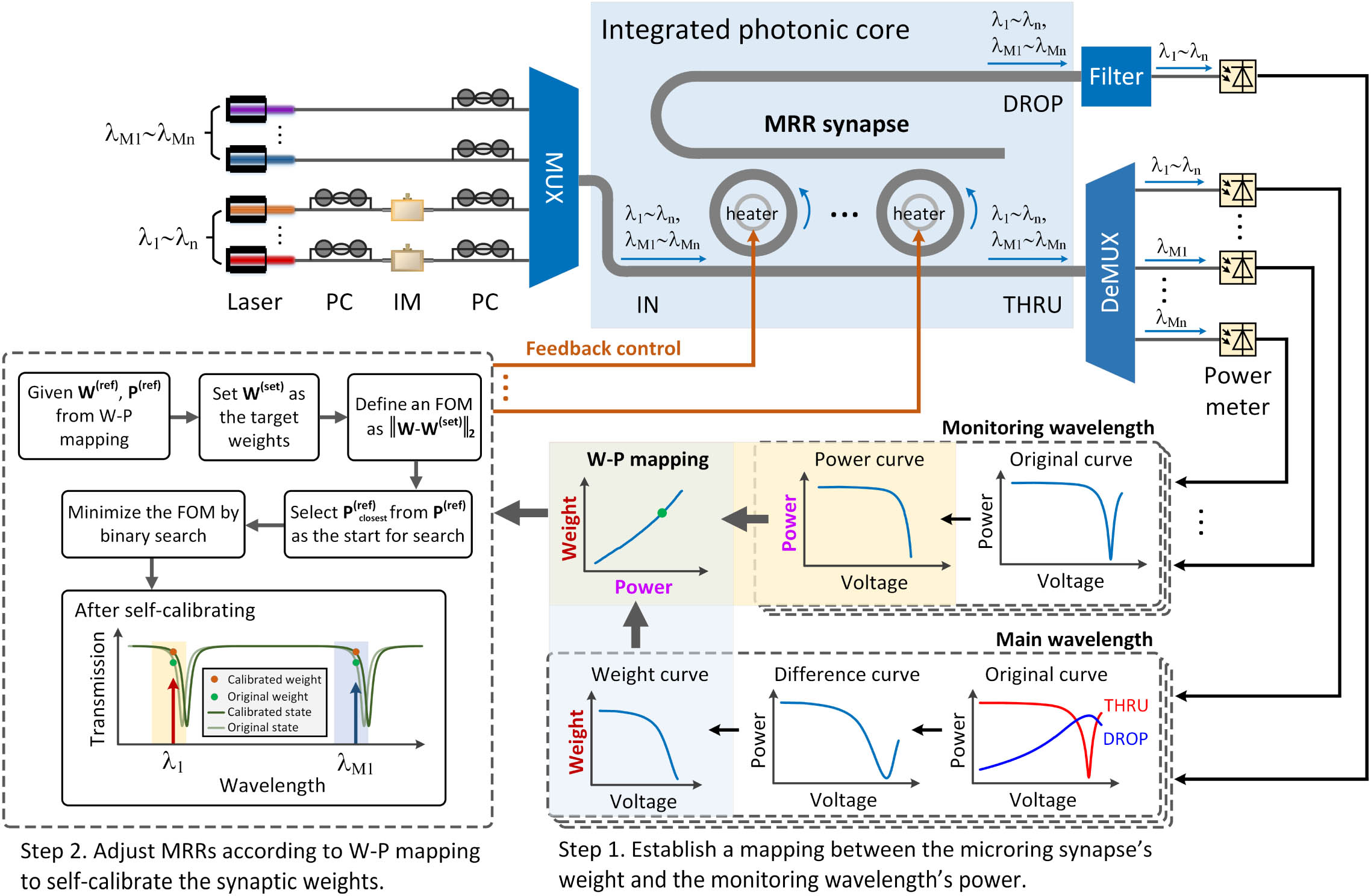
    Figure 1.Conceptual diagram of the self-calibrating microring synapse with dual-wavelength synchronization. Monitoring wavelengths are added to monitor and calibrate the synaptic weights, and a thermally insensitive mapping between the synaptic weights and monitoring wavelengths can be established to provide accurate initial reference points for the parameter update procedure.

    The self-calibration process can be summarized as two steps. The first step is to establish a mapping between the weights of the microring synapse and the power of the monitoring wavelength, and the second step is to adjust the microheater of the MRR to calibrate its weights. In the first step, the main wavelength is detected at the through (THRU) port and the drop (DROP) port, and then the weight-voltage (W-V) lookup curves can be established through differential processing. These W-V lookup curves provide initial reference points for self-calibration. At the same time, the corresponding power-voltage (P-V) lookup curves can be established by separately detecting the monitoring wavelengths at the THRU port. These P-V lookup curves show the mapping between the power of the monitoring wavelengths and the voltages applied to the MRRs, and the voltages also determine the weights of these MRRs. It should be noted that due to the synchronization of the dual wavelengths, the optical power of the monitoring wavelength and the weight of the main wavelength are synchronized, resulting in one-to-one mapping, which is also the premise of the validity of the proposed scheme. Next, we can obtain the weight-power (W-P) lookup curves by the already established W-V lookup curves and the P-V lookup curves, which directly correspond the weight information carried by the main wavelengths to the power of the monitoring wavelengths. The subsequent self-calibration process will be based on the W-P lookup curves established here. For one MRR in a microring synapse, there is a specific W-P lookup curve corresponding to it, which includes a weight set, W(ref):w1(ref),w2(ref),,wN(ref), and a power set, P(ref):p1(ref),p2(ref),,pN(ref), where N is the sample length. Each power, pn(ref),n[1,N], then uniquely determines its corresponding weight, wn(ref),n[1,N], of the MRR.

    In the second step, our self-calibration goal is to make the measured weights W closest to the target weights W(set) improve the analog computing precision. To evaluate the proximity of the two weight sets, we define a figure of merit (FOM) as the l2-norm between the measured one and the target one, as expressed by FOM=WW(set)2,where FOM[0,), meaning the lower the FOM value, the better proximity of the two weight sets. According to the W-P lookup curves established in the first step, we can find the reference weight that is closest to the target weight and its corresponding power value pclosest(ref) of the monitoring wavelength. The power meters will simultaneously record each individual weight corresponding to pclosest(ref) as a collection of the measured weights, W:w1,w2,,wN. To normalize the collection of measured weights, the maximum positive weight in the collection can be temporarily assigned as wmax=1 as the reference for determining other synaptic weights of this channel. Note that since the power of the monitoring wavelength is in one-to-one correspondence with the weight of the MRR, we only need to adjust the power of the monitoring wavelength to the correct value, and the corresponding weight of the MRR will naturally be in the correct position. During self-calibration, pclosest(ref) is taken as the starting position of the search, and the binary search is used to search for the appropriate power value near the starting position to minimize the value of the FOM. In addition, each MRR has a different monitoring wavelength, thus the weights of all channels can be monitored and adjusted simultaneously, and the required search time does not increase with the number of channels. The self-calibration procedure stops when the number of iterations reached the limit or the FOM is lower than the pre-defined threshold.

    Figure 2 shows the design details of the microring synapse. The device is designed on a silicon-on-insulator (SOI) platform with a 220-nm-thick silicon and a 2-μm-thick buried oxide layer, featuring a compact size of 2.6  mm×2.0  mm. As shown in Fig. 2(a), the MRR array consists of 4 four-MRR synapses, and the radius of the MRRs in each four-MRR synapse is designed to be gradual to avoid overlapping resonance peaks of different MRRs. Figure 2(b) shows the micrograph of the four-MRR synapse and the zoomed-in micrograph of an individual MRR. Thermo-optic phase shifters made of TiN heaters are used to tune the MRRs. Overall and detailed photos of the packaged layout are shown in Fig. 2(c), in which both wire bonding and vertical grating coupling have already been packaged for electrical and optical input/output (I/O). In addition, we specially designed a customed field-programmable gate array (FPGA) circuit and a digital-to-analog converter (DAC) circuit to achieve programmable voltages with 16-bit resolution to supply accurate voltages to the MRRs. The thermo-electric cooler (TEC) is mounted below the integrated microring synapse to control the environmental temperature and will be used in this work to test the robustness of the self-calibrating microring synaptic system. For a four-MRR synapse, four main wavelengths and four monitoring wavelengths are used in the experiment, corresponding to two adjacent sets of resonance peaks in the spectrum, as shown in Fig. 2(d). Our method only requires the monotonicity of adjacent resonance peaks to be consistent to establish the one-to-one mapping and does not require their transmission to be exactly the same. Because as long as the monotonicity of two sets of adjacent resonance peaks is consistent, the one-to-one mapping between the main wavelengths and the monitoring wavelengths can be established. Hence, when the power of the monitoring wavelength is adjusted to the correct value, the weight carried by the main wavelength will also be calibrated. Since all resonance peaks are separated from each other, the MRRs of the microring synapse can be independently configured, and thermal isolation trenches are employed between each microring synapse of the MRR array to minimize the thermal cross talk.

    Detailed design of the integrated microring synapse. (a) The schematic structure of the 4×4 MRR array. Different colors correspond to different wavelength channels. (b) The micrograph of the microring synapse cascading four MRRs and the zoomed-in micrograph of an individual MRR. (c) The overall and detailed photos of the packaged layout. The integrated photonic core is wire bonded with a tailored printed circuit board (PCB) and mounted on a thermo-electric cooler (TEC). The optical input and output (I/O) are through the fiber V groove on the top left. (d) The measured output spectral response of the MRR synapse at the THRU and DROP ports.

    Figure 2.Detailed design of the integrated microring synapse. (a) The schematic structure of the 4×4 MRR array. Different colors correspond to different wavelength channels. (b) The micrograph of the microring synapse cascading four MRRs and the zoomed-in micrograph of an individual MRR. (c) The overall and detailed photos of the packaged layout. The integrated photonic core is wire bonded with a tailored printed circuit board (PCB) and mounted on a thermo-electric cooler (TEC). The optical input and output (I/O) are through the fiber V groove on the top left. (d) The measured output spectral response of the MRR synapse at the THRU and DROP ports.

    The device is characterized by the experimental set-up that contains a C+L ASE light source (Amonics ALS-CL-15), a versatile tunable laser (ID Photonics CoBrite DX4), a custom programmable voltage source, an optical spectrum analyzer (Yokogawa AQ6370C), a multi-channel optical power meter (Luster OPM-1008), an optical tunable filter (Santec OTF-350), and two wavelength selective switches (Finisar WSS). The light polarization is controlled by a polarization beam splitter and a polarization controller before coupling into the grating coupler of the device under test. The loss of each grating coupler is measured to be around 3 dB at the central wavelength of 1550 nm.

    3. RESULTS

    In this section, we first experimentally validate the effectiveness of the proposed self-calibrating microring synapse with dual-wavelength synchronization, including two aspects: improved computing precision and robustness to environmental temperature changes. Next, we demonstrate the success of this self-calibrating microring synapse for matrix inversion tasks.

    A. Precision Test of the Two-MRR Synapse System

    Precision is always an important index for analog computing hardware, which determines its ability to deal with precision-demanded problems. State-of-the-art microelectronic hardware for AI computing, such as the Intel Loihi [40] and the Google tensor processing unit (TPU) [41], has 8-bit precision or higher. However, most optical synapses are limited to relatively low precision, typically 2 bits lower than that of microelectronic hardware, and thus there is an urgent need for an effective approach to improving the precision of optical hardware to meet the growing demand for AI applications.

    To show the effectiveness of the self-calibration scheme, we first tested the precision performance of an individual MRR. Before the self-calibration, we established the mapping between the MRR weights and the optical power of the monitoring wavelength, which is the W-P lookup curve mentioned above. Then, a main wavelength and a monitoring wavelength are simultaneously injected from the input port to evaluate the performance of the MRR. We swept the optical power of the monitoring wavelength by tuning the voltages applied to the TiN heater of the MRR to change the weights in equally spaced increments within the [–1, 1] interval. Figure 3 shows the comparison of the calibrated weights and theoretical weights of the individual MRR of the microring synapse. The blue dashed line (corresponding to the left vertical axis) indicates the W-P lookup curve established in advance, while the green dots (corresponding to the left vertical axis) represent the experimental calibrated weights obtained by the MRR self-calibrating scheme based on dual-wavelength synchronization. The error between these two weight values is calculated and plotted as the orange curve (corresponding to the right vertical axis). Results show that the error is basically within 1% over the whole weight range, [–1, 1], which confirms the effectiveness of our self-calibrating scheme.

    Comparison of the calibrated weights and theoretical weights of the individual MRR of the microring synapse.

    Figure 3.Comparison of the calibrated weights and theoretical weights of the individual MRR of the microring synapse.

    To further verify the effectiveness of the self-calibration scheme in a larger-scale situation, we then evaluate the performance of the self-calibration scheme on the two-MRR synapse system. Figures 4(a) and 4(b) show the error results on the heat map before and after the self-calibration process, respectively. The two MRRs in the microring synapse are tuned to (w1,w2),w1,2[1,1] with equidistant weight points. In the 9×9 heat map, each sub-square represents the error of one weight combination, and its color shade represents the magnitude of the error. The bit precision of the weights can be calculated from the standard deviation of the measured error marked on each sub-square of the heat map and then converted into bit-precision expression by the equation from Ref. [23], precision=log2[weightmax(1)weightmin(1)standard(error)].

    The calibration with dual-wavelength synchronization improves the precision of weighting in the two-MRR synapses. (a) The measurement of the weighting precision before the self-calibration. (b) The measurement of the weighting precision after the self-calibration. The weighting precision is evaluated at equally spaced weights on the heatmap. Each sub-square in the heatmap represents the weighting error of a measured weight, and its shade represents the magnitude of the error. (c) and (d) are the weighting error for the evaluation in (a) and (b), respectively, calculated as Δw=w−wset, where w is the measured weight and wset is the set weight. The dashed and solid circles correspond to different bit precisions to provide an intuitive distribution of weight precision.

    Figure 4.The calibration with dual-wavelength synchronization improves the precision of weighting in the two-MRR synapses. (a) The measurement of the weighting precision before the self-calibration. (b) The measurement of the weighting precision after the self-calibration. The weighting precision is evaluated at equally spaced weights on the heatmap. Each sub-square in the heatmap represents the weighting error of a measured weight, and its shade represents the magnitude of the error. (c) and (d) are the weighting error for the evaluation in (a) and (b), respectively, calculated as Δw=wwset, where w is the measured weight and wset is the set weight. The dashed and solid circles correspond to different bit precisions to provide an intuitive distribution of weight precision.

    Figures 4(c) and 4(d) show the aggregation of the errors derived from Figs. 4(a) and 4(b), respectively. The error points of weights are calculated as Δw=wwset, where w is the measured weight and wset is the set weight. The dashed and solid circles correspond to different bit precisions to provide an intuitive distribution of weight precision. Before calibration, most of the test points are distributed in the 5-bit range, while after calibration, most of the test points are clustered in solid circles representing 7-bit precision, indicating that the precision of the microring synapses can be improved from 5 bits to 7 bits, and the error is significantly reduced.

    B. Robustness Test against Temperature Fluctuations

    As a typical class of resonant devices, MRRs usually have a high Q factor and high sensitivity to temperature variations, and thus can be designed as temperature sensors [25,26]. However, the temperature sensitivity of the MRR makes it difficult to maintain the stability of the weights of the MRR when the environmental temperature fluctuates, which leads to a serious deterioration of the precision for analog optical computations.

    To resolve this issue, we applied our self-calibration scheme to the microring synapse and tested its robust performance against temperature fluctuations. As shown in Fig. 5, the tested weights consist of positive [Fig. 5(a)], zero [Fig. 5(b)], and negative weights [Figs. 5(c) and 5(d)], respectively. The whole test process contains three steps, including (I) origin, (II) temperature changes, and (III) weight self-calibrating. In the first step, we set the weights of the MRR to the target weights (weights=0.3,0,0.2,0.5) according to the W-P lookup curve pre-established at 20°C. In the second step, the environmental temperature is gradually increased from 20°C to 20.5°C using a thermo-electric cooler (TEC) module, and the weights of the MRR are recorded simultaneously by power meters. The curves in the II area of Fig. 5 show the weight deterioration process caused by environmental temperature changes. The third step is used to demonstrate the robust performance of the self-calibrating microring synapse against environmental temperature fluctuations. Due to the thermo-optical effect, changes in temperature affect the transmittance of the MRR, so the optical power of the monitoring wavelength is noticeably abnormal. Such anomalies are quickly identified, and the self-calibrating procedure is automatically activated and keep running. After a few dozen iterations at a temperature of 20.5°C, which is different from the temperature of pre-established W-P lookup curves, the weights of the MRR are successfully restored to the target weight, indicating that the weights of the MRR can be quickly corrected with a fast-converging training after the environmental temperature changes. Our test range includes positive, zero, and negative weights, and the results demonstrate the wide applicability of our self-calibration scheme with dual-wavelength synchronization.

    Robust performance of the self-calibrating microring synapse against environmental temperature fluctuations. The tested weights consist of positive, zero, and negative weights, including weight of (a) 0.3, (b) 0, (c) −0.2, and (d) −0.5.

    Figure 5.Robust performance of the self-calibrating microring synapse against environmental temperature fluctuations. The tested weights consist of positive, zero, and negative weights, including weight of (a) 0.3, (b) 0, (c) 0.2, and (d) 0.5.

    According to our experimental experience, current temperature variation range is close to the maximum range of temperature variations that our microring synapse and self-calibration algorithm can support. If the temperature variation range is further increased, the spectrum shift will be too large, which may cause the main wavelength and monitoring wavelength to shift out of the resonance peaks, and the microring cannot be calibrated back to the correct weight. Actually, the current temperature variation range is much larger than the fluctuation of the environmental temperature in usual experiments. As shown in Fig. 5, the weight will change dramatically due to the temperature variation, such as changing from 0.3 to 0.7, or even from 0.5 to 0.4, which is generally impossible in the usual experimental environment. Therefore, we believe that the current temperature variation range can already verify the effectiveness of our self-calibration scheme in terms of temperature stabilization.

    C. Demonstration of Matrix Inversion Tasks

    In the era of big data, where matrix inversion is an important and fundamental linear algebra operation, modern AI models are usually converted to linear algebra problems to support the heavy workload. Compared to the MVM, matrix inversion is more computationally complex and usually needs to be solved by iteration-based methods. For an N×N matrix, the computational complexity of the matrix inverse is generally O(N3) and that of MVM is just O(N2), and thus matrix inversion requires analog computing hardware to support higher computational precision and stability to ensure that high-precision iterations can be performed smoothly. As an effective and fast-convergence method for computing the matrix inversion, the Newton’s iterative algorithm was first proposed several decades ago [42], and it has been widely used in industrial and academic applications [43,44] and is also considered a benchmark for matrix inversion to compare with the performance of the newly proposed algorithms [45]. The Newton’s iterative method uses iterative numerical linear algebra to compute the matrix inversion, which starts with an initial guess of the solution matrix and updates the approximate solution in iterations of the algorithm, further minimizing the difference between the approximate solution and the target solution at each step. The Newton’s iteration can be expressed as Xn=X0·(2·IA·X0),where Xn is the target solution, X0 is the approximate solution, I is the identity matrix, and AR is the initial input matrix. However, the iterative process is often accompanied by the accumulation of errors. Once the error is too large, the algorithm cannot converge, and hence the computing precision is of great significance for the Newton’s iterative method. To illustrate the effect of the precision on Newton’s iterative method, we perform numerical simulations of the matrix inversion model based on the Newton iteration at different weight precisions. In each iteration, the Gaussian random noise is added to every matrix element, and the intensity of Gaussian noise is set with bit precision of 4 bits, 5 bits, 6 bits, 7 bits, and 8 bits, respectively, to evaluate the impact of computing precision on the feasibility of matrix inversion based on Newton’s iterative method. Figure 6 shows the simulation results of Newton’s iterative method for matrix inversion tasks with different bit precisions. The error function is designed to describe the difference between the approximate solution and the correct solution. The larger the error function is, the greater the difference between the approximate solution and the correct solution will be, while a smaller error function indicates that the approximate solution and the correct solution are closer. The simulation results show that the matrix inversion can be successfully achieved by Newton’s iterative method only when the computational precision reaches 7 bits or more.

    Simulation results of Newton’s iterative method for matrix inversion tasks with bit precision of 4 bits, 5 bits, 6 bits, 7 bits, and 8 bits.

    Figure 6.Simulation results of Newton’s iterative method for matrix inversion tasks with bit precision of 4 bits, 5 bits, 6 bits, 7 bits, and 8 bits.

    To further evaluate the practical precision performance of the proposed microring synapse, we experimentally demonstrate the Newton’s iteration-based matrix inversion task implemented by the proposed microring synapse. The task is to perform Newton iteration using optical hardware to calculate the inverse matrix of the given initial matrix, and the schematic of the computation flow is shown in Fig. 7(a). For an individual Newton’s iteration, MVM operations are optically performed by the photonic MRR synapses, and the subtraction operation of the output values of the MRR synapses is electrically executed on the customed FPGA circuit. Without loss of generality, we test several different initial matrices. The test results show that matrix inversion in the real domain can be successfully implemented, and Fig. 7 shows the matrix inversion based on Newton’s iteration for two different initial matrices A1R,A2R, A1=(10.20.40.420.50.30.62),A2=(20.30.50.210.40.40.62),where the theoretical inverse of A1 and A2 can be calculated as A11=(0.87550.15140.21300.22480.50170.08050.19880.12780.4922),A21=(0.56920.29110.20050.18111.22900.29110.16820.42690.6274).

    Matrix inversion based on Newton’s iteration for two different initial matrices. (a) The implementation of an individual Newton’s iteration expressed by Eq. (3). (b) The theoretical and experimental results for the initial matrix A1. (c) The error distribution of the inverse of A1. (d) The theoretical and experimental results for the initial matrix A2. (e) The error distribution of the inverse of A2.

    Figure 7.Matrix inversion based on Newton’s iteration for two different initial matrices. (a) The implementation of an individual Newton’s iteration expressed by Eq. (3). (b) The theoretical and experimental results for the initial matrix A1. (c) The error distribution of the inverse of A1. (d) The theoretical and experimental results for the initial matrix A2. (e) The error distribution of the inverse of A2.

    Figure 7(b) shows the theoretical and experimental results for the inversion of matrix A1, and the corresponding error distribution is shown in Fig. 7(c). Similarly, Fig. 7(d) shows the theoretical and experimental results for the inversion of matrix A2, and the corresponding error distribution is shown in Fig. 7(e). In the whole computation flow, the self-calibration procedure is employed to ensure that the computing precision can meet the requirements of matrix inversion tasks. According to the error distribution of matrix inversion, most elements have absolute errors less than 0.1, and over 75% of the elements have absolute errors less than 0.06. The results indicate that the experimental values are in excellent agreement with the theoretical values, and the matrix inversion based on Newton’s iteration can be achieved by the microring synapse with dual-wavelength synchronization.

    4. DISCUSSION

    Feedback weight calibration is essential to a microring synapse system with stability and dynamic operation ability. In our scheme, the concepts of monitoring wavelength and dual-wavelength synchronization are first proposed and demonstrated for the weight calibration of the microring synapses. Since the monitoring wavelengths and the main wavelengths used for computations are separated by one FSR and do not overlap, they are independent of each other, and changes in the amplitude of the input signal modulated by the intensity modulators do not affect the monitoring of the MRR weights. The MRR weight information carried by the main wavelengths can be obtained based on the synchronized monitoring wavelengths and the pre-established mapping. Table 1 summarizes the comparison of our weight monitoring scheme with three mainstream schemes in terms of several metrics.

    Comparison of Our Weight Monitoring Scheme with Three Mainstream Schemes

    Tap Coupler Scheme [33,34]Temperature Sensor Scheme [46]Dithering Control Scheme [23,30]Dual-wavelength Scheme (This Work)
    Independent MonitoringNoYesYesYes
    Immunity to Temperature FluctuationsNoNoNoYes
    Precision Improvement1–2 bits1–2 bits2–4 bits2  bits
    Extra Power LossRequiredNot requiredNot requiredNot required
    ScalabilityLimited by power lossLimited by fabrication processLimited by calibration speedStrong (benefit from optical combs)

    Compared with previous works, our scheme has several advantages. Computation and weight monitoring are implemented simultaneously and independently of each other. Based on the spectral characteristics of the MRR and the dual-wavelength synchronization, the optical power of the monitoring wavelength is in one-to-one correspondence with the MRR weight and will not be affected by the amplitude of the modulated input signal.Immunity to temperature fluctuations. Temperature fluctuations do not change the relative position and synchronization of the main wavelengths and the monitoring wavelengths, and thus the W-P mapping is naturally insensitive to temperature fluctuations, which fundamentally determines the advantage of this scheme in robust performance against temperature fluctuations.Significant precision improvement and fast convergence. Our scheme is an optoelectronic hybrid closed-loop feedback system that operates without human intervention. The real-time feedback and efficient binary search enable 2-bit precision improvement and fast convergence for weight self-calibration.Flexible scalability for the potential of large-scale microring synapses. On the one hand, each MRR only needs one additional “plug-and-play” monitoring wavelength, which can support the weight monitoring function under the premise of compatibility with the existing architecture. On the other hand, compared with the monitoring schemes based on power splitters, the proposed scheme does not induce extra power loss.

    Although our scheme achieves a precision improvement of 2 bits, it still falls short of the current highest precision record. Admittedly, the main limitation of our present work is the lack of the entire optical link consisting of the laser load, the intensity modulators, the radio frequency signal, the microring synapse, and the power meters. In particular, our scheme requires a constant interval between the monitoring wavelength and the main wavelength, and hence the wavelength instability of the laser will lead to errors. We believe that with the realization of the entire optical link monitoring, our scheme will be able to achieve precision comparable to the current state-of-the-art records.

    5. CONCLUSION

    In summary, we propose and demonstrate a self-calibration scheme with dual-wavelength synchronization, featuring the monitoring wavelengths independently parallel from computations and a thermally insensitive W-P mapping for the weight calibration of the microring synapses. To boost the calibration speed, on-demand FPGA circuits are designed to replace bulky instruments, while feedback control and fine-tuning of the MRRs are performed based on binary search algorithms and W-P mapping. We test the integrated microring synapse in terms of the precision improvement of the synaptic weights and the robustness against temperature fluctuations to evaluate the practical effectiveness of the scheme. As an optoelectronic hybrid closed-loop feedback control, this scheme supports fast-converging parameter update and iteration, which enables 2-bit precision improvement for the microring synapse. Moreover, our scheme is immune to the environmental temperature fluctuations, and the weights can be corrected within 1 s after the temperature changes 0.5°C. In addition, we demonstrate Newton iterations beyond 7-bit precision realized by MRRs and perform matrix inversion tasks in the real-value domain. Our self-calibration scheme paves the way for analog optical computing, especially overcoming the environmental vulnerability of resonator-based architectures, such as microring synapses, to perform high-precision computational tasks on optical hardware.

    References

    [1] Y. Shen, N. C. Harris, S. Skirlo, M. Prabhu, T. Baehr-Jones, M. Hochberg, X. Sun, S. Zhao, H. Larochelle, D. Englund, M. Soljačić. Deep learning with coherent nanophotonic circuits. Nat. Photonics, 11, 441-446(2017).

    [2] A. N. Tait, T. F. de Lima, E. Zhou, A. X. Wu, M. A. Nahmias, B. J. Shastri, P. R. Prucnal. Neuromorphic photonic networks using silicon photonic weight banks. Sci. Rep., 7, 7430(2017).

    [3] J. Feldmann, N. Youngblood, M. Karpov, H. Gehring, X. Li, M. Stappers, M. Le Gallo, X. Fu, A. Lukashchuk, A. S. Raja, J. Liu, C. D. Wright, A. Sebastian, T. J. Kippenberg, W. H. P. Pernice, H. Bhaskaran. Parallel convolutional processing using an integrated photonic tensor core. Nature, 589, 52-58(2021).

    [4] S. Xu, J. Wang, H. Shu, Z. Zhang, S. Yi, B. Bai, X. Wang, J. Liu, W. Zou. Optical coherent dot-product chip for sophisticated deep learning regression. Light Sci. Appl., 10, 221(2021).

    [5] X. Xu, M. Tan, B. Corcoran, J. Wu, A. Boes, T. G. Nguyen, S. T. Chu, B. E. Little, D. G. Hicks, R. Morandotti, A. Mitchell, D. J. Moss. 11 TOPS photonic convolutional accelerator for optical neural networks. Nature, 589, 44-51(2021).

    [6] T. Zhou, X. Lin, J. Wu, Y. Chen, H. Xie, Y. Li, J. Fan, H. Wu, L. Fang, Q. Dai. Large-scale neuromorphic optoelectronic computing with a reconfigurable diffractive processing unit. Nat. Photonics, 15, 367-373(2021).

    [7] F. Ashtiani, A. J. Geers, F. Aflatouni. An on-chip photonic deep neural network for image classification. Nature, 606, 501-506(2022).

    [8] M. Rafayelyan, J. Dong, Y. Tan, F. Krzakala, S. Gigan. Large-scale optical reservoir computing for spatiotemporal chaotic systems prediction. Phys. Rev. X, 10, 041037(2020).

    [9] M. Borghi, S. Biasi, L. Pavesi. Reservoir computing based on a silicon microring and time multiplexing for binary and analog operations. Sci. Rep., 11, 15642(2021).

    [10] X. X. Guo, S. Y. Xiang, Y. Qu, Y. N. Han, A. J. Wen, Y. Hao. Enhanced prediction performance of a neuromorphic reservoir computing system using a semiconductor nanolaser with double phase conjugate feedbacks. J. Lightwave Technol., 39, 129-135(2021).

    [11] D. Pierangeli, G. Marcucci, C. Conti. Large-scale photonic Ising machine by spatial light modulation. Phys. Rev. Lett., 122, 213902(2019).

    [12] D. Pierangeli, G. Marcucci, C. Conti. Adiabatic evolution on a spatial-photonic Ising machine. Optica, 7, 1535-1543(2020).

    [13] M. Prabhu, C. Roques-Carmes, Y. Shen, N. Harris, L. Jing, J. Carolan, R. Hamerly, T. Baehr-Jones, M. Hochberg, V. Čeperić, J. D. Joannopoulos, D. R. Englund, M. Soljačić. Accelerating recurrent Ising machines in photonic integrated circuits. Optica, 7, 551-558(2020).

    [14] B. J. Shastri, A. N. Tait, T. Ferreira de Lima, W. H. P. Pernice, H. Bhaskaran, C. D. Wright, P. R. Prucnal. Photonics for artificial intelligence and neuromorphic computing. Nat. Photonics, 15, 102-114(2021).

    [15] D. C. Tzarouchis, M. J. Mencagli, B. Edwards, N. Engheta. Mathematical operations and equation solving with reconfigurable metadevices. Light Sci. Appl., 11, 263(2022).

    [16] H. Zhou, J. Dong, J. Cheng, W. Dong, C. Huang, Y. Shen, Q. Zhang, M. Gu, C. Qian, H. Chen, Z. Ruan, X. Zhang. Photonic matrix multiplication lights up photonic accelerator and beyond. Light Sci. Appl., 11, 30(2022).

    [17] M. Lundstrom. Moore’s law forever?. Science, 299, 210-211(2003).

    [18] L. Yang, R. Ji, L. Zhang, J. Ding, Q. Xu. On-chip CMOS-compatible optical signal processor. Opt. Express, 20, 13560-13565(2012).

    [19] V. Bangari, B. A. Marquez, H. Miller, A. N. Tait, M. A. Nahmias, T. F. de Lima, H.-T. Peng, P. R. Prucnal, B. J. Shastri. Digital electronics and analog photonics for convolutional neural networks (DEAP-CNNs). IEEE J. Sel. Top. Quantum Electron., 26, 7701213(2020).

    [20] C. Huang, S. Fujisawa, T. F. de Lima, A. N. Tait, E. C. Blow, Y. Tian, S. Bilodeau, A. Jha, F. Yaman, H.-T. Peng, H. G. Batshon, B. J. Shastri, Y. Inada, T. Wang, P. R. Prucnal. A silicon photonic-electronic neural network for fibre nonlinearity compensation. Nat. Electron., 4, 837-844(2021).

    [21] Y. Jiang, W. Zhang, F. Yang, Z. He. Photonic convolution neural network based on interleaved time-wavelength modulation. J. Lightwave Technol., 39, 4592-4600(2021).

    [22] J. Cheng, Y. Zhao, W. Zhang, H. Zhou, D. Huang, Q. Zhu, Y. Guo, B. Xu, J. Dong, X. Zhang. A small microring array that performs large complex-valued matrix-vector multiplication. Front. Optoelectron., 15, 15(2022).

    [23] W. Zhang, C. Huang, H.-T. Peng, S. Bilodeau, A. Jha, E. Blow, T. F. de Lima, B. J. Shastri, P. Prucnal. Silicon microring synapses enable photonic deep learning beyond 9-bit precision. Optica, 9, 579-584(2022).

    [24] A. N. Tait, M. A. Nahmias, B. J. Shastri, P. R. Prucnal. Broadcast and weight: an integrated network for scalable photonic spike processing. J. Lightwave Technol., 32, 4029-4041(2014).

    [25] H. Xu, M. Hafezi, J. Fan, J. M. Taylor, G. F. Strouse, Z. Ahmed. Ultra-sensitive chip-based photonic temperature sensor using ring resonator structures. Opt. Express, 22, 3098-3104(2014).

    [26] H.-T. Kim, M. Yu. Cascaded ring resonator-based temperature sensor with simultaneously enhanced sensitivity and range. Opt. Express, 24, 9501-9510(2016).

    [27] H. Jayatilleka, H. Shoman, R. Boeck, N. A. F. Jaeger, L. Chrostowski, S. Shekhar. Automatic configuration and wavelength locking of coupled silicon ring resonators. J. Lightwave Technol., 36, 210-218(2018).

    [28] H. Jayatilleka, H. Shoman, L. Chrostowski, S. Shekhar. Photoconductive heaters enable control of large-scale silicon photonic ring resonator circuits. Optica, 6, 84-91(2019).

    [29] F. Zanetto, V. Grimaldi, M. Moralis-Pegios, S. Pitris, K. Fotiadis, T. Alexoudi, E. Guglielmi, D. Aguiar, P. D. Heyn, Y. Ban, J. V. Campenhout, N. Pleros, G. Ferrari, M. Sampietro, A. Melloni. WDM-based silicon photonic multi-socket interconnect architecture with automated wavelength and thermal drift compensation. J. Lightwave Technol., 38, 6000-6006(2020).

    [30] K. Padmaraju, D. F. Logan, T. Shiraishi, J. J. Ackert, A. P. Knights, K. Bergman. Wavelength locking and thermally stabilizing microring resonators using dithering signals. J. Lightwave Technol., 32, 505-512(2014).

    [31] A. N. Tait, H. Jayatilleka, T. F. De Lima, P. Y. Ma, M. A. Nahmias, B. J. Shastri, S. Shekhar, L. Chrostowski, P. R. Prucnal. Feedback control for microring weight banks. Opt. Express, 26, 26422-26443(2018).

    [32] C. Huang, S. Bilodeau, T. F. de Lima, A. N. Tait, P. Y. Ma, E. C. Blow, A. Jha, H.-T. Peng, B. J. Shastri, P. R. Prucnal. Demonstration of scalable microring weight bank control for large-scale photonic integrated circuits. APL Photon., 5, 040803(2020).

    [33] A. Annoni, E. Guglielmi, M. Carminati, S. Grillanda, P. Ciccarella, G. Ferrari, M. Sorel, M. J. Strain, M. Sampietro, A. Melloni, F. Morichetti. Automated routing and control of silicon photonic switch fabrics. IEEE J. Sel. Top. Quantum Electron., 22, 169-176(2016).

    [34] P. Dong, R. Gatdula, K. Kim, J. H. Sinsky, A. Melikyan, Y.-K. Chen, G. de Valicourt, J. Lee. Simultaneous wavelength locking of microring modulator array with a single monitoring signal. Opt. Express, 25, 16040-16046(2017).

    [35] X. Xu, G. Ren, T. Feleppa, X. Liu, A. Boes, A. Mitchell, A. J. Lowery. Self-calibrating programmable photonic integrated circuits. Nat. Photonics, 16, 595-602(2022).

    [36] H. Zhou, Y. Zhao, Y. Wei, F. Li, J. Dong, X. Zhang. All-in-one silicon photonic polarization processor. Nanophotonics, 8, 2257-2267(2019).

    [37] H. Zhou, Y. Zhao, X. Wang, D. Gao, J. Dong, X. Zhang. Self-configuring and reconfigurable silicon photonic signal processor. ACS Photon., 7, 792-799(2020).

    [38] H. Zhou, Y. Zhao, G. Xu, X. Wang, Z. Tan, J. Dong, X. Zhang. Chip-scale optical matrix computation for pagerank algorithm. IEEE J. Sel. Top. Quantum Electron., 26, 8300910(2020).

    [39] J. Cheng, W. Zhang, W. Gu, H. Zhou, J. Dong, X. Zhang. Photonic emulator for inverse design. ACS Photon..

    [40] M. Davies, N. Srinivasa, T.-H. Lin, G. Chinya, Y. Cao, S. H. Choday, G. Dimou, P. Joshi, N. Imam, S. Jain. Loihi: a neuromorphic manycore processor with on-chip learning. IEEE Micro, 38, 82-99(2018).

    [41] A. Graves, G. Wayne, M. Reynolds, T. Harley, I. Danihelka, A. Grabska-Barwińska, S. G. Colmenarejo, E. Grefenstette, T. Ramalho, J. Agapiou, A. P. Badia, K. M. Hermann, Y. Zwols, G. Ostrovski, A. Cain, H. King, C. Summerfield, P. Blunsom, K. Kavukcuoglu, D. Hassabis. Hybrid computing using a neural network with dynamic external memory. Nature, 538, 471-476(2016).

    [42] V. Pan, J. Reif. Fast and efficient parallel solution of dense linear systems. Comput. Math. Appl., 17, 1481-1491(1989).

    [43] Y. Wang, H. Leib. Sphere decoding for MIMO systems with Newton iterative matrix inversion. IEEE Commun. Lett., 17, 389-392(2013).

    [44] C. Tang, C. Liu, L. Yuan, Z. Xing. High precision low complexity matrix inversion based on newton iteration for data detection in the massive MIMO. IEEE Commun. Lett., 20, 490-493(2016).

    [45] Y. Zhang, W. Ma, B. Cai. From Zhang neural network to Newton iteration for matrix inversion. IEEE Trans. Circuits Syst. I Reg. Papers, 56, 1405-1415(2009).

    [46] S. Saeedi, A. Emami. Silicon-photonic PTAT temperature sensor for micro-ring resonator thermal stabilization. Opt. Express, 23, 21875-21883(2015).

    Junwei Cheng, Zhenming He, Yuhao Guo, Bo Wu, Hailong Zhou, Teyan Chen, Yixin Wu, Wenwei Xu, Jianji Dong, Xinliang Zhang. Self-calibrating microring synapse with dual-wavelength synchronization[J]. Photonics Research, 2023, 11(2): 347
    Download Citation