
Ran GUO, Yue-Ming WANG. A self-calibration method of the boresight angles of airborne hyperspectral VNIR/SWIR modules[J]. Journal of Infrared and Millimeter Waves, 2023, 42(6): 851
- Journal of Infrared and Millimeter Waves
- Vol. 42, Issue 6, 851 (2023)
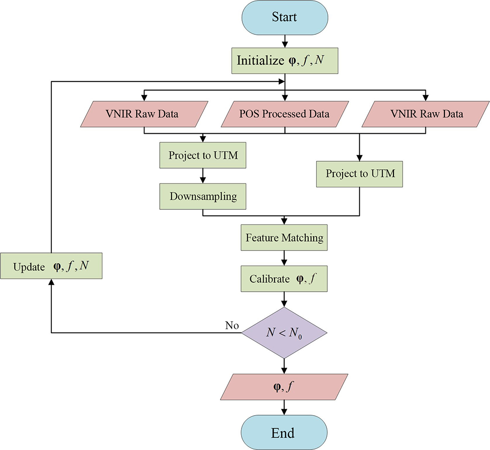
Fig. 1. The algorithm flowchart of boresight angle calibration

Fig. 2. The schematic diagram of the AMMIS optical system for a single VNIR subsystem
Fig. 3. The schematic diagram of the AMMIS optical system for a single SWIR subsystem
Fig. 4. The imaging modes of six VNIR/SWIR subsystems
Fig. 5. The definition of camera coordinate system and the illustration of projection process
Fig. 6. The effect of boresight angles on forward intersection (blue is before applying disturbance to boresight angles,red is after applying disturbance to boresight angles)
Fig. 7. The schematic diagram of flight direction and imaging subsystem identification
Fig. 8. The distribution of feature points in VNIR images captured by camera group 1 and their local enlargements,Note:red dots are the locations of feature points
Fig. 9. The distribution of feature points in SWIR images captured by camera group 1 and their local enlargements,Note:blue dots are the locations of feature points
Fig. 10. The schematic diagram of Dist in the rasterized image with ΔX,ΔY in UTM coordinate system
Fig. 11. The influence of various feature selection methods on the results of feature point selection (a case study using the first group of camera)
Fig. 12. Checkerboard images projected in UTM coordinate system for VNIR and SWIR data using various methods
Fig. 13. The comparative analysis of reprojection error and projection plane altitude error using random search and approximate formulas (a case study using the second group of camera)
Fig. 14. The peprojection error of VNIR and SWIR images from three sets of cameras with original parameters
Fig. 15. The reprojection error of VNIR and SWIR images from three sets of cameras with our method
Fig. 16. The reprojection error of VNIR and SWIR images from three sets of cameras calibrated with homography constraints and our method
Fig. 17. The reprojection error of VNIR and SWIR images from three sets of cameras with homography constraints
|
Table 1. Core parameters of the AMMIS VNIR/SWIR hyperspectral imaging subsystem
|
Table 2. Number of features extracted from VNIR and SWIR images
|
Table 3. The calibration result of the boresight angles and focal length scale
| ||||||||||||||||||||||||||||||||||||||||||||||||||||
Table 4. The comparison of reprojection error in UTM coordinate system before and after calibration
| |||||||||||||||||||||||||||||||||||
Table 5. Quadratic curve fitting results for the relationship between Y-direction reprojection error and Dist
|
Table 6. Euler angles derived from the decomposition of the homography matrix

Set citation alerts for the article
Please enter your email address
© Copyright 2018-2021 | Chinese Laser Press. All Rights Reserved 沪ICP备15018463号-20