• Photonics Research
  • Vol. 11, Issue 9, 1583 (2023)
Gangyi Zhu1、*, Xin Ji1, Zhenfu Zhang2, Xingcan Yan1, Ying Yang1, Feifei Qin1, Xin Li1, Jiagui Wu3, Xiaojuan Sun4, Junbo Yang2、5, and Yongjin Wang1
Author Affiliations
  • 1GaN Optoelectronic Integration International Cooperation Joint Laboratory of Jiangsu Province, Nanjing University of Posts and Telecommunications, Nanjing 210003, China
  • 2College of Arts & Science, National University of Defense Technology, Changsha 410003, China
  • 3School of Physical Science and Technology, Southwest University, Chongqing 400715, China
  • 4State Key Laboratory of Luminescence and Applications, Changchun Institute of Optics, Fine Mechanics and Physics, Chinese Academy of Sciences, Changchun 130033, China
  • 5e-mail: yangjunbo@nudt.edu.cn
  • show less
    DOI: 10.1364/PRJ.490145 Cite this Article Set citation alerts
    Gangyi Zhu, Xin Ji, Zhenfu Zhang, Xingcan Yan, Ying Yang, Feifei Qin, Xin Li, Jiagui Wu, Xiaojuan Sun, Junbo Yang, Yongjin Wang. Electrically pumped optomechanical beam GaN-LED accelerometer based on the quantum-confined Stark effect[J]. Photonics Research, 2023, 11(9): 1583 Copy Citation Text show less
    Fabrication process of GaN-LED accelerometer with beam structure: (a) patterning the photoresist, (b) etching to the n-GaN layer, (c) patterning the photoresist layer again, (d) etching to the Si substrate layer, (e) patterning the photoresist layer and preparing electrode, and (f) wet isotropic etching of silicon. Schematics of beam GaN-LED accelerometers with two structures: (g) type I, (h) type II. (i) Cross-sectional image for part of the GaN beam devices.
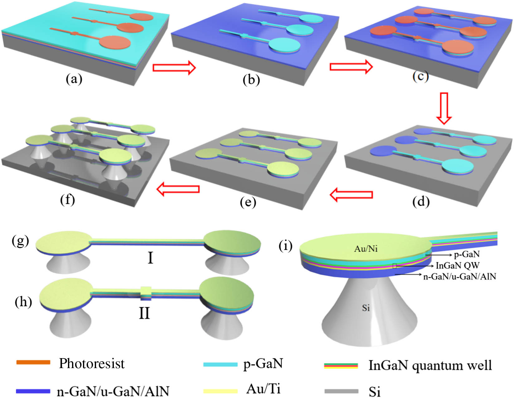
    Fig. 1. Fabrication process of GaN-LED accelerometer with beam structure: (a) patterning the photoresist, (b) etching to the n-GaN layer, (c) patterning the photoresist layer again, (d) etching to the Si substrate layer, (e) patterning the photoresist layer and preparing electrode, and (f) wet isotropic etching of silicon. Schematics of beam GaN-LED accelerometers with two structures: (g) type I, (h) type II. (i) Cross-sectional image for part of the GaN beam devices.
    SEM images of GaN-LED accelerometer with beam structure. (a) Top view of type I device; (b) side view of type I device; (c) top view of type II device; (d) side view of type II device; (e) enlarged image of the top view of sensitive mass block; (f) array of type II device.
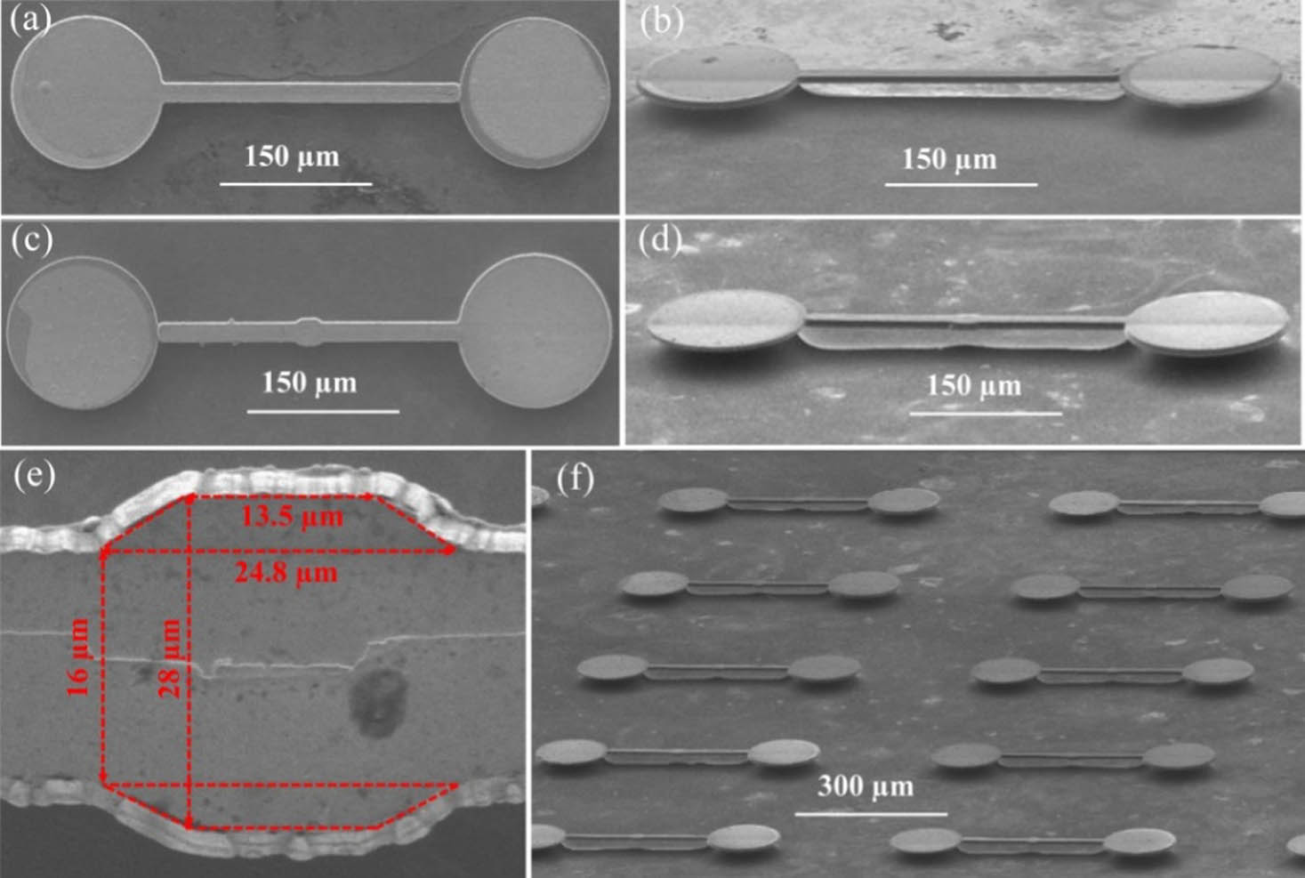
    Fig. 2. SEM images of GaN-LED accelerometer with beam structure. (a) Top view of type I device; (b) side view of type I device; (c) top view of type II device; (d) side view of type II device; (e) enlarged image of the top view of sensitive mass block; (f) array of type II device.
    Luminous images of the beams: (a) type I accelerometer, (b) type II accelerometer. EL spectra of the two types of beam GaN-LED accelerometers measured at different injection currents: (c) type I accelerometer, (e) type II accelerometer. (d) The emission intensity of two types of accelerometers at different injection currents. (f) The full width at half-maximum (FWHM) of the two types of beam GaN-LED accelerometers at different injection currents.
    Fig. 3. Luminous images of the beams: (a) type I accelerometer, (b) type II accelerometer. EL spectra of the two types of beam GaN-LED accelerometers measured at different injection currents: (c) type I accelerometer, (e) type II accelerometer. (d) The emission intensity of two types of accelerometers at different injection currents. (f) The full width at half-maximum (FWHM) of the two types of beam GaN-LED accelerometers at different injection currents.
    (a) I–V curves of the two types of beam GaN-LED accelerometers. The inset shows the data in logscale. (b) C–V curves of two types of accelerometers at a frequency of 100 kHz. (c) Relationship between the peak EL wavelength and injection current for the two types of GaN-LED accelerometers; the inset displays a schematic of the InGaN QW’s polarization direction, (d) beam displacement of the two types of GaN-LED accelerometers under standard gravity field obtained using COMSOL simulation.
    Fig. 4. (a) IV curves of the two types of beam GaN-LED accelerometers. The inset shows the data in logscale. (b) CV curves of two types of accelerometers at a frequency of 100 kHz. (c) Relationship between the peak EL wavelength and injection current for the two types of GaN-LED accelerometers; the inset displays a schematic of the InGaN QW’s polarization direction, (d) beam displacement of the two types of GaN-LED accelerometers under standard gravity field obtained using COMSOL simulation.
    (a) Beam stress distribution of beam GaN-LED device; (b) enlarged stress distribution of the device. (c) Vertical (Z axis) displacement and (d) horizontal (Y axis) displacement of the device. The acceleration is 1.8×10⁶ m/s2.
    Fig. 5. (a) Beam stress distribution of beam GaN-LED device; (b) enlarged stress distribution of the device. (c) Vertical (Z axis) displacement and (d) horizontal (Y axis) displacement of the device. The acceleration is 1.8×10⁶  m/s2.
    SEM images of type II device with PS. (a) Top view, (b) side view. (c) Enlarged image of beam structure with PS.
    Fig. 6. SEM images of type II device with PS. (a) Top view, (b) side view. (c) Enlarged image of beam structure with PS.
    (a) EL spectra of the type II device after adding PS at different injection currents. (b) I–V curves of type II device before and after adding PS; the inset image displays the illumination of the beam structure. (c) Relationship between peak wavelength of EL spectra and injection current before and after adding the PS. (d) Displacement of the beam before and after adding PS under standard gravity field.
    Fig. 7. (a) EL spectra of the type II device after adding PS at different injection currents. (b) IV curves of type II device before and after adding PS; the inset image displays the illumination of the beam structure. (c) Relationship between peak wavelength of EL spectra and injection current before and after adding the PS. (d) Displacement of the beam before and after adding PS under standard gravity field.
    Gangyi Zhu, Xin Ji, Zhenfu Zhang, Xingcan Yan, Ying Yang, Feifei Qin, Xin Li, Jiagui Wu, Xiaojuan Sun, Junbo Yang, Yongjin Wang. Electrically pumped optomechanical beam GaN-LED accelerometer based on the quantum-confined Stark effect[J]. Photonics Research, 2023, 11(9): 1583
    Download Citation