• Advanced Photonics Nexus
  • Vol. 2, Issue 6, 066009 (2023)
Yanqi Liu1、2、†, Keyang Liu1、3, Zhaoyang Li1、2、*, Yuxin Leng1、*, and Ruxin Li1、2、4、*
Author Affiliations
  • 1Chinese Academy of Sciences, Shanghai Institute of Optics and Fine Mechanics, State Key Laboratory of High Field Laser Physics, Shanghai, China
  • 2Zhangjiang Laboratory, Shanghai, China
  • 3Chinese Academy of Sciences, Xi’an Institute of Optics and Precision Mechanics, Center for Attosecond Science and Technology, Xi’an, China
  • 4ShanghaiTech University, Shanghai, China
  • show less
    DOI: 10.1117/1.APN.2.6.066009 Cite this Article Set citation alerts
    Yanqi Liu, Keyang Liu, Zhaoyang Li, Yuxin Leng, Ruxin Li. Coherently tiled Ti:sapphire laser amplification: a way to break the 10 petawatt limit on current ultraintense lasers[J]. Advanced Photonics Nexus, 2023, 2(6): 066009 Copy Citation Text show less
    (a) Schematic of a large-sized Ti:sapphire amplifier with a four-pass signal and two-surface pumps. Details in the front surface are enlarged. TASE is transverse-amplified spontaneous emission, c is the crystal axis, and GT and GL are the transverse and longitudinal gains, respectively. Equal scaling of the large-sized Ti:sapphire amplifier from shown in (a) to (b) extralarge-sized and (c) tiled Ti:sapphire amplifiers; signal beams are not shown for convenience. (d) Surface transverse gain GT(0) and longitudinal gain GL as functions of pump energy for single-surface pumping, 200 mm Ti:sapphire size, and 1 cm−1 pump absorption coefficient. (e) Instantaneous surface transverse gain GT(z=0,t=0) as a function of Ti:sapphire size D for a fixed 150/202 J/cm2 instantaneous surface pump fluence. Threshold of parasitic lasing GT=2110 is marked in (d) and (e).
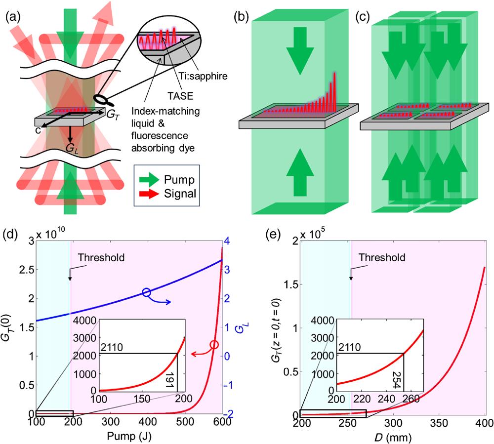
    Fig. 1. (a) Schematic of a large-sized Ti:sapphire amplifier with a four-pass signal and two-surface pumps. Details in the front surface are enlarged. TASE is transverse-amplified spontaneous emission, c is the crystal axis, and GT and GL are the transverse and longitudinal gains, respectively. Equal scaling of the large-sized Ti:sapphire amplifier from shown in (a) to (b) extralarge-sized and (c) tiled Ti:sapphire amplifiers; signal beams are not shown for convenience. (d) Surface transverse gain GT(0) and longitudinal gain GL as functions of pump energy for single-surface pumping, 200 mm Ti:sapphire size, and 1  cm1 pump absorption coefficient. (e) Instantaneous surface transverse gain GT(z=0,t=0) as a function of Ti:sapphire size D for a fixed 150/202  J/cm2 instantaneous surface pump fluence. Threshold of parasitic lasing GT=2110 is marked in (d) and (e).
    (a) Schematics of (2×2) CBC and (2×2) CTT. x−y−t are space–time coordinates defined at the focus. Focused pulsed beams in x−y, t−x, and t−y planes (b) without and (c) with tiling errors. In panel (c), three subbeams have horizontal angle, vertical angle, and longitudinal piston errors of (2 μrad, 1 μrad, and 500 nm), (−1 μrad, −2 μrad, and −500 nm), and (1 μrad, −2 μrad, and 200 nm) relative to a fixed subbeam, respectively. (d) Focused intensity If stability for 100 shots when three subbeams have random tiling errors of [−2, 2 μrad] horizontal angle, [−2, 2 μrad] vertical angle, and [−500, 500 nm] longitudinal piston relative to a fixed subbeam, the first shot shows the ideal case without tiling errors, and the probability density function is given.
    Fig. 2. (a) Schematics of (2×2) CBC and (2×2) CTT. xyt are space–time coordinates defined at the focus. Focused pulsed beams in xy, tx, and ty planes (b) without and (c) with tiling errors. In panel (c), three subbeams have horizontal angle, vertical angle, and longitudinal piston errors of (2  μrad, 1  μrad, and 500 nm), (1  μrad, 2  μrad, and 500  nm), and (1  μrad, 2  μrad, and 200 nm) relative to a fixed subbeam, respectively. (d) Focused intensity If stability for 100 shots when three subbeams have random tiling errors of [2,2  μrad] horizontal angle, [2,2  μrad] vertical angle, and [500,500  nm] longitudinal piston relative to a fixed subbeam, the first shot shows the ideal case without tiling errors, and the probability density function is given.
    (a) Experimental setup and a collimated signal beam is divided by a 2×2 square diaphragm into four subbeams which pass through a 2×2 tiled Ti:sapphire crystal 4 times. Reproduced with permission from Ref. 22. Copyright 2022, Wiley. Pump 1 is shaped by a square diaphragm and divided by a beam splitter into two beams to irradiate subcrystals A and C at the back surfaces. Similarly, pump 2 irradiates subcrystals A and C at front surfaces, pump 3 irradiates subcrystals B and D at the back surfaces, and pump 4 irradiates subcrystals B and D at the front surfaces. Photographs of the 2×2 tiled Ti:sapphire crystal and the 2×2 square diaphragm are shown. Four subcrystals are marked by A–D. (b) Measured (left) and simulated (right) near-field (upper) and far-field (lower) beam patterns and four subbeams are marked by A–D in the near field. (c) Measured wavefront. (d) Energy stability for 28 shots. (e) Measured spectra in different amplifiers. RA, regenerative amplifier; Amp1, amplifier 1; Amp2, amplifier 2; and TTA, tiled Ti:sapphire amplifier. (f) Measured compressed pulses and phases of subbeams A–D.
    Fig. 3. (a) Experimental setup and a collimated signal beam is divided by a 2×2 square diaphragm into four subbeams which pass through a 2×2 tiled Ti:sapphire crystal 4 times. Reproduced with permission from Ref. 22. Copyright 2022, Wiley. Pump 1 is shaped by a square diaphragm and divided by a beam splitter into two beams to irradiate subcrystals A and C at the back surfaces. Similarly, pump 2 irradiates subcrystals A and C at front surfaces, pump 3 irradiates subcrystals B and D at the back surfaces, and pump 4 irradiates subcrystals B and D at the front surfaces. Photographs of the 2×2 tiled Ti:sapphire crystal and the 2×2 square diaphragm are shown. Four subcrystals are marked by A–D. (b) Measured (left) and simulated (right) near-field (upper) and far-field (lower) beam patterns and four subbeams are marked by A–D in the near field. (c) Measured wavefront. (d) Energy stability for 28 shots. (e) Measured spectra in different amplifiers. RA, regenerative amplifier; Amp1, amplifier 1; Amp2, amplifier 2; and TTA, tiled Ti:sapphire amplifier. (f) Measured compressed pulses and phases of subbeams A–D.
    (a) Schematic of improving 10 to 40 PW by four-pass 2×2 tiled Ti:sapphire amplifier. Electric fields after a compressor and at a focus for (b) single beam, (c) 2×2 beam array consisting of four subbeams, and (d) 2×2 beam array consisting of four subbeams with a 1.33 fs time delay τ (i.e., 400 nm piston Δz) between upper two and lower two subbeams. Frequency of the carrier wave is multiplied by 0.5 to avoid fast oscillation in (b)–(d). (e) Focused intensity of pulsed beams as a function of time delay τ (or piston Δz) between upper two and lower two subbeams in 2×2 beam array. Results of temporal and spatial coherent combinations for two ray pulses (Ps) in time and two monochromatic beams (Bs) in far field are given for reference.
    Fig. 4. (a) Schematic of improving 10 to 40 PW by four-pass 2×2 tiled Ti:sapphire amplifier. Electric fields after a compressor and at a focus for (b) single beam, (c) 2×2 beam array consisting of four subbeams, and (d) 2×2 beam array consisting of four subbeams with a 1.33 fs time delay τ (i.e., 400 nm piston Δz) between upper two and lower two subbeams. Frequency of the carrier wave is multiplied by 0.5 to avoid fast oscillation in (b)–(d). (e) Focused intensity of pulsed beams as a function of time delay τ (or piston Δz) between upper two and lower two subbeams in 2×2 beam array. Results of temporal and spatial coherent combinations for two ray pulses (Ps) in time and two monochromatic beams (Bs) in far field are given for reference.
    Layout and parameters of the Ti:sapphire CPA laser facility for experimental demonstration. The red beamline is the signal, the green beamlines are pumps, and the dashed box indicates the final amplifier using CTT.
    Fig. 5. Layout and parameters of the Ti:sapphire CPA laser facility for experimental demonstration. The red beamline is the signal, the green beamlines are pumps, and the dashed box indicates the final amplifier using CTT.
    Yanqi Liu, Keyang Liu, Zhaoyang Li, Yuxin Leng, Ruxin Li. Coherently tiled Ti:sapphire laser amplification: a way to break the 10 petawatt limit on current ultraintense lasers[J]. Advanced Photonics Nexus, 2023, 2(6): 066009
    Download Citation