
Yanqi Liu, Keyang Liu, Zhaoyang Li, Yuxin Leng, Ruxin Li. Coherently tiled Ti:sapphire laser amplification: a way to break the 10 petawatt limit on current ultraintense lasers[J]. Advanced Photonics Nexus, 2023, 2(6): 066009
- Advanced Photonics Nexus
- Vol. 2, Issue 6, 066009 (2023)
Abstract
Keywords
1 Introduction
Femtosecond petawatt (fs-PW) ultraintense lasers, which are produced by chirped-pulse amplification (CPA),1 have opened and accelerated the research and development of plasma physics, particle physics, astrophysics, nuclear physics, etc. in the past two decades.2
Technically, two problems of the fs-PW Ti:sapphire ultraintense lasers, namely, small crystal size (Ti:sapphire) and parasitic lasing,18 limit the significant increase in the maximum pulse energy, as well as the highest intensity. First, it is difficult to fabricate Ti:sapphire crystals now, and second, even with large Ti:sapphire crystals, the strong transverse amplified spontaneous emission (TASE) and its induced parasitic lasing can dramatically consume the stored pump energy in the case of strong pumping, thus significantly reducing the pump-to-signal conversion efficiency.19 Although there are many methods to suppress TASE and parasitic lasing, such as two-surface pumping, lightly doped Ti:sapphire crystal, refractive-index matching, TASE absorbing, pump-signal delay, and multiple-pulse pump, none of them can solve these problems completely. Because of this, the recently started project of the Station of Extreme Light 100 PW (SEL-100PW) at Shanghai, China20, has chosen to use optical parametric chirped-pulse amplification (OPCPA) technology21 to reach 100 PW by increasing the energy to 1500 J and reducing the pulse to 15 fs. The OPCPA technology certainly has its advantages over the Ti:sapphire CPA technology, such as having a broader bandwidth, a larger crystal size (e.g., deuterated potassium dihydrogen phosphate), no parasitic lasing, and no saturation gain narrowing,22 but it also has its disadvantages, such as low-pump-to-signal conversion efficiency, poor beam quality, and low spatiotemporal stability.
The Ti:sapphire CPA, a proven and successful technology that has produced two 10 PW ultraintense lasers,9,10 will still play an important role in enabling the future of 50 to 100 PW ultraintense lasers. For example, coherently combining 10 beams of 10 PW Ti:sapphire CPA ultraintense lasers is one way to reach 100 PW;23 tenfold reducing the pulses of a 10 PW Ti:sapphire CPA ultraintense laser with postcompression from to 30 fs to 2.5 to 3 fs is another way to 100 PW24. In engineering, each of these two approaches has its own difficulties; for example, the former will face the problems of precision space–time control, high cost, and huge engineering, while the latter will face the problems of small-scaled self-focusing, precision dispersion management, and optics damage. Some new concepts are also being proposed one after another, which still need time to be tested in engineering.25
Sign up for Advanced Photonics Nexus TOC. Get the latest issue of Advanced Photonics Nexus delivered right to you!Sign up now
2 Results and Discussion
2.1 Truncating Transverse Amplified Spontaneous Emission
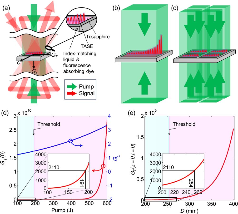
Figure 1(a) shows the schematic of a typical strongly pumped large-size Ti:sapphire amplifier. Pumps irradiate two surfaces of the Ti:sapphire crystal and are absorbed, and a signal is amplified in energy after four-pass. is the crystal axis, and and are longitudinal and transverse gains that determine the signal amplification and the parasitic lasing (or TASE), respectively. If the crystal is thick and all the pump energy is absorbed, the longitudinal gain is given by19
![]()
Figure 1.(a) Schematic of a large-sized Ti:sapphire amplifier with a four-pass signal and two-surface pumps. Details in the front surface are enlarged. TASE is transverse-amplified spontaneous emission,
Equation (1) shows that the pump fluence dominates the longitudinal gain . For example, two 10 PW ultraintense lasers (SULF and ELI-NP), the final amplifiers have pump energies at a 532 nm wavelength and Ti:sapphire crystals. For convenience, if assuming a square Ti:sapphire crystal, as well as square beams, the pump fluence is , the longitudinal gain (at 800 nm) is [see Fig. 1(d)], and a signal can be amplified to after a three/four-pass.9,10 Equation (2) shows that the surface pump fluence or , the pump absorption coefficient , and the crystal size determine the highest transverse gains, and , which appear at the two surfaces of the crystal. Usually for suppressing parasitic lasing, a relatively small pump absorption coefficient is chosen ( in this paper), and a refractive-index-matching liquid with a fluorescence-absorbing dye is used to reduce Fresnel reflections at interfaces and to absorb the TASE.18 When using the 1-bromonaphthalene (), the parasitic lasing threshold is for ,35 where is the Fresnel reflection ratio at the interface. Figure 1(d) shows that when all the 600 J pump energy irradiates the front surface of a 200 mm Ti:sapphire crystal, the surface transverse gain is , substantially exceeding the parasitic lasing threshold of 2110. When the 600 J pump is divided into two 300 J pumps irradiating the two surfaces of the crystal, the surface transverse gain or is , which is still too high. In this case, control in time is required;9,10 for example, in the ELI-NP’s three-pass final-amplifier,10 at each surface of the crystal, the 300 J pump is further divided in time into three pulses: 150, 75, and 75 J pump pulses irradiate the crystal before the first pass, before the second pass, and before the third pass of the signal, respectively. The total pump energy of 600 J remains unchanged, but the highest instantaneous surface transverse gain or is reduced to [see Fig. 1(d) for a 150 J pump], below the threshold of 2110, successfully achieving signal energy amplification from to .
If we keep the optimized pump fluence and instantaneous surface pump fluence constant as described above [i.e., and ] and then increase the total pump energy as well as the Ti:sapphire crystal area to achieve higher energy operation, Fig. 1(e) shows that as the crystal size increases linearly from 200 to 400 mm (if available), the instantaneous surface transverse gain or increases exponentially from to again, substantially exceeding the parasitic lasing threshold of 2110 again. This can be well explained by Eq. (2), which shows that the instantaneous surface transverse gain or is exponentially related to the product of the instantaneous surface pump fluence or and the crystal size . The results show that by simply increasing the crystal size linearly (if available), the transverse gain will increase exponentially, and parasitic lasing makes it impossible to achieve an increase in energy and then in peak power [see Fig. 1(b)]. However, Fig. 1(c) shows that, when using a tiled Ti:sapphire crystal, the gaps filled with refractive-index-matching liquids and fluorescence-absorbing dyes will truncate the TASE and then avoid the parasitic lasing, which becomes the only way to boost energy. The current 10 PW ultraintense laser may be enhanced to 40 PW by adding a tiled Ti:sapphire amplifier containing four 200 mm crystals pumped by four 600 J pumps. For convenience, four square subcrystals are considered, which can be cut from our homemade 280 mm circle Ti:sapphire crystals. When cutting from slightly smaller circle ones (e.g., 200 mm), square subcrystals with rounded corners would not significantly affect the performance here, either.
2.2 Tiling Errors Analysis
Tiling error control has always been a problem for CBC, which happens to be the strength of CTT. Figure 2(a) shows very simplified schematics of the CBC and the CTT. In the former, a signal beam is divided into four beams that are amplified and compressed in four parallel channels, each containing an amplifier and a compressor. The four output beams are coherently combined by different mirrors to form a beam array, which is then focused by a single large parabola. In the latter, the signal beam is expanded by a telescope and filtered by a diaphragm into a beam array that is amplified in a tiled Ti:sapphire amplifier, compressed in a single large compressor, and focused by a single large parabola. Using the simulation parameters given in Appendix A, Fig. 2(b) shows the focused pulsed beam without any tiling error in the , , and planes, where and are horizontal and vertical spatial axes at the focus and is the temporal axis (along the propagation axis). Both a Fourier-transform limit pulse and a diffraction limit focal spot are obtained simultaneously, and sidelobes around the focal spot are due to gaps in the beam array.
![]()
Figure 2.(a) Schematics of (
In practice, however, tiling errors are inevitable in CBC due to mechanical vibrations, electrical instabilities, etc. in different channels and at different mirrors. We fix one subbeam in the beam array as a reference and give the other three subbeams horizontal angle errors of 2, , and ; vertical angle errors of 1, , and ; and longitudinal piston errors of 500, , and 200 nm. Figure 2(c) shows the focal spot in the plane distorts seriously, and the focused pulsed beam has a spatiotemporal distortion in the plane and an interference split in the plane. Figure 2(d) shows the stability of the focused intensity for 100 independent shots. The first shot is the focused intensity without any tiling error in Fig. 2(b), which is normalized to the reference standard “1” for comparison. The other 99 shots are the results when the three subbeams have random horizontal angle errors of , random vertical angle errors of , and random longitudinal piston errors of relative to the fixed subbeam, and the probability density function for these 99 random vibrations shows a mean value of only around 0.25, which significantly compromises the goal of using CBC to increase the focused intensity. Similar conclusions have also been presented in several previous works.36,37
In CTT, the beam array is spatially filtered from an expanded large beam and experiences the same optical path, which contains all large aperture optics (e.g., mirrors, gratings, and a parabola), except for a tiled Ti:sapphire crystal (subcrystals are well fixed), so that relative vibrations between different subbeams are effectively avoided. The main problems include the time delay and the wavefront error among subbeams, which is caused by thickness differences and fixing errors of the subcrystals in the tiled Ti:sapphire crystal, which will be experimentally and theoretically studied in the sections below.
2.3 Experimental Demonstration
We have successfully demonstrated a , , tiled Ti:sapphire amplifier in the experimental facility described in Appendix B. Figure 3(a) shows the amplifier has two sets of beamlines, and the upper (red) and the lower (green) are the signal and the pump, respectively. The tiled Ti:sapphire crystal consisted of four subcrystals (we mark them by A, B, C, and D here), and the gaps between them are 6 mm. During the fabrication, the four subcrystals were processed together, including cutting (the orientations of optical axes), polishing, and coating, to obtain a near-ideal tiling condition. To match the tiled Ti:sapphire crystal, the signal beam was spatially filtered into a beam array by a diaphragm, which was then reflected 7 times by mirrors to pass through the tiled Ti:sapphire crystal 4 times. The diaphragm had four soft-edged square holes, and the gaps were also 10 mm. The pump beamline consisted of four beams of pumps 1 to 4, which were injected into the amplifier from the four corners of the lower set beamline. Figure 3(a) shows the elements in the optical path of pump 1: a soft-edged square diaphragm changed the beam from circular to square, a spatial filter improved the beam quality, and importantly, imaged it onto the crystals. A 50:50 beam splitter divided the beam into two beams and reflected one beam onto the back surface of subcrystal A, and a mirror reflected the other beam onto the back surface of subcrystal C. The two beams from pump 2 irradiated the front surfaces of subcrystals A and C, and pump 2 was symmetrical with pump 1 about the crystal. The two beams from pump 3 and pump 4, respectively, irradiated the back and the front surfaces of the subcrystals B and D, and pump 3 and pump 4 were symmetrical with pump 1 and pump 2 about the normal of the crystal.
![]()
Figure 3.(a) Experimental setup and a collimated signal beam is divided by a
The input energy of the beam array filtered by the square diaphragm was about 343 mJ, and the amplified energy was about 5 J. Since the total energy of the 532 nm pumps was , the pump-to-signal conversion efficiency was about 41.6%. In the experiment, with an absorption coefficient of , approximately 86% of the pump energy was absorbed. With a higher absorption coefficient and/or longer crystals, the pump-to-signal conversion efficiency could be further improved. Finally, the entire beam, i.e., beam array, was injected into a double-pass grating compressor with and large gratings to remove the temporal chirp, which output 3.5 J near-Fourier-transform-limit pulses, corresponding to a throughput efficiency of 70%.
Figure 3(b) shows the measured patterns in the near and far fields of the beam array (with a focal length of 1 m) and the corresponding simulation results for comparison, and the two results agree well. The eight sidelobes around the main focal spot in the far field were caused by gaps between the subbeams in the near field and could be efficiently suppressed by increasing the ratio between the subbeam and the gap (10/10 here). For example, in the 40 PW ultraintense laser design in this paper, this ratio is increased to 200/30 in the amplifier and 400/60 in the compressor, with very weak sidelobes relative to the main focal spot, as shown in Fig. 2(b). During experiments, we observed the main focal spot for a long time without spot splitting or separating, which corresponds to the longitudinal piston error and the horizontal/vertical angular error, respectively,31 indicating that tiling errors were well avoided in CTT. Figure 3(c) shows the measured wavefront of the entire beam, which has four small wavefronts corresponding to four subbeams A, B, C, and D. The peak-to-valley values of the subbeams A, B, C, and D were 0.2, 0.2, 0.1, and , respectively, while that of the entire beam was . All four wavefronts of the four subbeams were located in the same large wavefront, which indicates that the tiled Ti:sapphire crystal did not distort the wavefront of the entire beam. The stability of the output energy was measured for 28 shots, and Fig. 3(d) shows the values are stable and near 5 J. The measured spectra of the four subbeams after the tiled Ti:sapphire amplifier are in very good agreement, and that of subbeam A is shown by the blue curve in Fig. 3(e). The spectra before the tiled Ti:sapphire amplifier, i.e., after the regenerative amplifier, amplifier 1, and amplifier 2, are also given. The compressed pulses of the four subbeams were measured in the near field and are given in Fig. 3(f) with highly consistent pulses and phases. The pulse durations (full width at half-maximum, FWHM) of the subbeams A, B, C, and D are 30.5, 30.9, 30.4, and 30.9 fs, respectively. Although the pulse duration at the focus was not directly measured, the measured plane wavefront and the near-ideal focal spot of the entire beam indicate that the four pulsed beams arrived at the focus at the same time; otherwise, the four small subbeams that are separated in time would enlarge the focal spot size and thus deviate from the ideal one.22
2.4 Extrapolation from 10 to 40 PW
The excellent spatial, temporal, and spectral homogeneity of the four subbeams in the 2 × 2 beam array demonstrated in the above experiments allows CTT to enhance the current 10 PW ultraintense lasers to 40 PW. Concerning the final amplifier of the ELI-NP 10 PW ultraintense laser where an 80 J signal has been amplified to 330 J in a 600 J pumped 200 mm large-sized Ti:sapphire crystal,9Fig. 4(a) schematically shows a 330 J signal in a 10 PW ultraintense laser (before the compressor) is divided into a beam array with energy in each subbeam by a diaphragm. It is then injected into an added tiled Ti:sapphire amplifier consisting of four 200 mm square subcrystals, where the energy can be amplified from to by a pump. In fact, each subbeam in the tiled Ti:sapphire amplifier is equivalent to the current final amplifier of the ELI-NP or SULF, whereas CTT solves a key problem of spatiotemporal combination. In the above experiments, the spectral optimization for broadening the bandwidth was not used, which is now a common technique for obtaining short pulses of in the 10 PW ultraintense lasers.9,10 In this case, a 22 fs, 880 J, and 40 PW ultraintense laser could be produced in the near future by the tiled Ti:sapphire amplification technique when a grating compressor with a throughput efficiency is used.
![]()
Figure 4.(a) Schematic of improving 10 to 40 PW by four-pass
Figure 4(a) shows in the current 10 PW ultraintense lasers, the beam size in the amplifier is limited by the Ti:sapphire crystal (e.g., ) and needs to be expanded (e.g., from to ) before the compressor to avoid damage to the gratings. In the designed 40 PW ultraintense laser, after the added tiled Ti:sapphire amplifier, the entire beam size of the beam array also needs to be expanded (e.g., from to ) by a telescope before the compressor. Figure 4(b) shows compressed and focused (2 + 1)-D spatiotemporal electric fields of a 400 mm square beam in the domains, corresponding to a 10 PW laser, based on the simulation parameters given in Appendix A. To observe the spatiotemporal structure of electric fields, the carrier frequency is multiplied by 0.5 to avoid a fast oscillation. Figure 4(c) shows the results of a beam array consisting of four 400 mm square subbeams with two 60 mm gaps, corresponding to a 40 PW laser. Compared with the result in Fig. 4(b), because the total energy is increased by a factor of 4, the focal spot area is reduced to 1/4, and then the focused intensity is enhanced by a factor of 16. However, the time delay between the subbeams affects the achievement of this ideal result. In a tiled Ti:sapphire crystal, thickness differences and fixing errors of the subcrystals will introduce very small optical path differences (i.e., time delays) to the subbeams. Even when these subcrystals are cut, polished, and coated together, these differences cannot be eliminated completely. Figure 3(a) shows that in the four-pass tiled Ti:sapphire amplifier, the upper-two subbeams pass through the subcrystals A and B twice and they undergo exactly the same optical path with no time delay between them. Similarly, the lower two subbeams also undergo the same optical path (pass through the subcrystals C and D twice), there is no time delay between them either. When the upper two and the lower two subbeams have an optical path difference of 1/2 wavelength (i.e., a piston error of 400 nm or a time delay of 1.33 fs in vacuum), Fig. 4(d) shows that the focused pulsed beam splits into two spots in space and some spatiotemporal distortions can also be found, which can degrade the focused intensity. Compared to the focused intensity without any tiling error (i.e., time delay or longitudinal piston error is 0) in Fig. 4(c), the reference standard of “1,” Fig. 4(e) shows that the normalized focused intensity oscillates down as the time delay between the upper two and the lower two subbeams increases from 0 to 20 fs (or the longitudinal piston error from 0 to ). The oscillation is caused by the interference of pulsed beams in space and time. For comparison, Fig. 4(e) also gives the results of the temporal coherent combination of two ray pulses in time and the spatial coherent combination of two monochromatic beams in the far field. In the experiments above, we did not observe any interference-induced focal spot splitting in the long-time operation, indicating that the time delay (or the longitudinal piston error) is very small and that the time delay vibration is (or the longitudinal piston error vibration is ). In engineering, with a small time delay (or longitudinal piston error) between subbeams, it can be detected by observing focal spot splitting31 and then corrected by deformable mirrors, thin glasses, etc. Therefore, it is feasible to engineer a normalized focused intensity .
3 Conclusion
We analyzed TASE truncation, parasitic lasing suppression, and tiling error avoidance of the CTT technique and experimentally demonstrated a tiled Ti:sapphire amplifier in a , , and laser facility. The results show that even with extra-large-sized Ti:sapphire crystals (if available), TASE and parasitic lasing will consume stored pump energy, preventing signal laser amplification. The CBC technique is limited by tiling errors, and its focused intensity is usually much lower than the ideal value. The CTT technique solves both problems well and offers the possibility of breaking the current 10 PW limit to reach 40 PW in a Ti:sapphire CPA system. The experiments have shown that the tiled Ti:sapphire amplifier has the same pump-to-signal conversion efficiency as the conventional Ti:sapphire amplifier. There is no significant difference between the two in terms of laser amplification. What is important is that all subbeams in the beam array filtered from an expanded beam can maintain good spatial, temporal, and spectral homogeneity during amplification, propagation, compression, and focusing, facilitating the improvement of peak powers and focused intensities. The main problem is the time delay between subbeams in the beam array, which can be detected by observing focal spots and removed by deformable mirrors.
The feature of CTT is that after the tiled Ti:sapphire amplifier, the entire beam (i.e., the subbeam array) is reflected, diffracted, and focused by the same optics without any spatial separation. Thus, at the rear end, the overall size of of the beam array (with 400 mm square subbeams and 60 mm gaps) requires about 1.5 m mirrors, gratings, and 1.6 m parabola, all of which are being manufactured at the Shanghai Institute of Optics and Fine Mechanics, Chinese Academy of Sciences, China now. The gold-coated commercial gratings have been available since 2018.10 Currently, the large-size optics are not a bottleneck for the realization of 40 PW ultraintense lasers. In the future, when adding a thin-plate/film postcompressor after the grating compressor to reduce the pulse duration from to , the peak power would be further enhanced from 40 to 100 PW.24,25
In conclusion, the CTT technique is expected to break the bottleneck of current Ti:sapphire CPA ultraintense lasers and achieve higher output. Its advantageous effects in terms of TASE truncation, parasitic lasing suppression, and tiling error avoidance are theoretically analyzed and high conversion-efficiency energy amplification with high-quality spatial, temporal, and spectral homogeneity was successfully demonstrated in a laser facility. This work provides a technique to further improve current Ti:sapphire CPA ultraintense lasers from 10 to 40 PW or higher.
4 Appendix A: Simulation Parameters
Referring to the current two 10 PW ultraintense lasers, the pulse in the simulation has a six-order super-Gaussian spectrum, an 800 nm center wavelength, and a 75 nm FWHM bandwidth, which therefore corresponds to a FWHM duration. Because a 2× telescope is considered between the final amplifier and the grating compressor in order to avoid damage to the gratings, the beam array (for both CBC and CTT) have 200 and 400 mm square subbeams and 30 and 60 mm gaps in the final amplifier and in the grating compressor, respectively. The focal length of the parabola after the grating compressor is 2 m.
5 Appendix B: Experimental Details
The layout and parameters of the experimental facility used for the demonstration are shown in Fig. 5. A commercial Ti:sapphire oscillator outputs a 12 fs, 25 nJ, and 80 MHz mode-locked seed, which is stretched in time to 2.4 ns by an Offner grating stretcher with an energy efficiency of around 20%. A regenerative amplifier amplifies the pulse energy to 2 mJ and reduces the repetition rate to 10 Hz. Two six-pass Ti:sapphire amplifiers further amplify the pulse energy to 45 and 850 mJ, respectively. A beam array is filtered from the expanded beam in a beam shaper and injected into a four-pass tiled Ti:sapphire amplifier, where the pulse energy is amplified from 343 mJ to . Finally, a grating compressor compensates the temporal chirp of the energy-amplified beam array, achieving an output of 30.7 fs, 3.5 J, and 114 TW. The pumps for the Ti:sapphire amplifiers are 532 nm frequency-doubled Neodymium-doped Yttrium aluminum garnet (Nd:YAG) Q-switched lasers, the energy parameters of which at different amplifiers are given in Fig. 5.
![]()
Figure 5.Layout and parameters of the Ti:sapphire CPA laser facility for experimental demonstration. The red beamline is the signal, the green beamlines are pumps, and the dashed box indicates the final amplifier using CTT.
In the experiments, pulse energies are measured by two energy meters from Gentec-EO (QE8SP-B-BL-D0) and Ophir (PE50BF-DIFH-C ROHS), spectra are measured by a fiber spectrometer from Ideaoptics (PG4000-EX), pulse profiles and phases are measured by Wizzler from Fastlite (WizzlerUSP8), beam patterns are measured by a charge-coupled device from Spiricon (BeamGage SP503U), and wavefronts are measured by a Shack–Hartmann sensor from Thorlabs (WFS40-7AR).
Yanqi Liu is an associate professor at Zhangjiang Laboratory, Shanghai, China, with interests in ultra-intense laser technology and engineering. He received his bachelor’s and master’s degrees from Changchun University of Science and Technology in 2007 and 2011, respectively. He was a research assistant, research associate, and associate professor at Shanghai Institute of Optics and Fine Mechanics (SIOM), Chinese Academy of Sciences (CAS) from 2011 to 2022.
Keyang Liu is an assistant professor at Xi’an Institute of Optics and Precision Mechanics, CAS, with interests in ultrafast laser technology and engineering. He received his bachelor’s and doctoral degrees from Xi’an Shiyou University and SIOM, CAS in 2016 and 2021, respectively. He has been an assistant professor at Xi’an Institute of Optics and Precision Mechanics, CAS since 2021.
Zhaoyang Li is a professor at Zhangjiang Laboratory, Shanghai, China, with interests in ultra-intense laser technology and engineering. He received his bachelor’s, master’s, and doctoral degrees from Beijing Institute of Technology, China Academy of Engineering Physics, and Nanjing University of Science and Technology, respectively. He was an assistant professor at Institute of Laser Engineering, Osaka University, at SIOM, and at Shanghai Institute of Laser Plasma.
Yuxin Leng is a professor at SIOM, CAS, Shanghai, China, with interests in ultra-intense lasers and physics. He received his bachelor’s and doctoral degrees from Wuhan University and SIOM, CAS in 1997 and 2002, respectively. He is an assistant/associate/full professor at SIOM, CAS; the director of Stake Key Laboratory of High Field Laser Physics, SIOM, CAS; and the vice director of SIOM, CAS.
Ruxin Li is a professor at SIOM, CAS, Shanghai, China, with interests in ultra-intense lasers and physics. He received his bachelor’s and doctoral degrees from Tianjin University and SIOM, CAS in 1990 and 1995, respectively. He was elected as the fellow of Optica (formerly OSA) in 2014, the Academician of CAS in 2017, and the Academician of Third World Academy of Sciences in 2021.

Set citation alerts for the article
Please enter your email address
© Copyright 2018-2021 | Chinese Laser Press. All Rights Reserved 沪ICP备15018463号-20