
Juan DU, Lei LIU, Yifeng YU, Yue ZHANG, Haijun LÜ, Aibing CHEN. Hollow Carbon Sphere with Tunable Structure by Encapsulation Pyrolysis Synchronous Deposition for Cefalexin Adsorption [J]. Journal of Inorganic Materials, 2020, 35(5): 608
- Journal of Inorganic Materials
- Vol. 35, Issue 5, 608 (2020)
Abstract
Keywords
Hollow carbon spheres (HCS) continue to be a research focus due to their unique properties such as high surface-to-volume ratios, and excellent chemical and thermal stabilities[
Polystyrene spheres (PS), a typical polymer, are often used as self-sacrifice hard template for hollow sphere due to its easy removal through changing into waste organic gases. Meanwhile, it can also be used as a promising carbon precursor due to high carbon content, facile preparation and adjustable diameter. Therefore, it is facilitate to prepare hollow carbon nanostructures by using PS spheres as carbon sources directly.
Generally, crosslinking or metal catalysis enable it to transform into carbon materials. Some methods (e. g. Friedel-Crafts reaction) was used for preparation of functional carbon materials using PS as carbon precursor[
Herein, we reported a novel synthesis of HCS with tailorable nano-size and shell thickness using an encapsulation pyrolysis synchronous deposition. The key to this approach was to encapsulate the easily decomposed PS in a compact silica shell. Thermal decomposable polymer nanosphere (PN) was encapsulated in compact silica shell and then transform into volatile carbonaceous species which deposited on the HCS to form a carbon layer, instead of the common process of crosslinking or metal catalysis. The diameter size of the HCS could be tunable by simple adjusting the size of PS core. Moreover, HCS with different thickness of carbon shell were also obtained through simply changing the amount of TEOS, facile and efficient for the synthesis of well-defined HCS, which may provide a potential platform for treatment of antibiotic wastewater.
1. Experimental
1.1 Synthesis of PS nanoparticles
PS nanoparticles with different diameter size were prepared by following the previous methods with slight modification [
1.2 Preparation of HCS
To prepare polymer/silica nanohybrids (named PS@SiO2) nanoparticles, we dispersed 0.2 mL of as- prepared PS nanoparticles (124 mg) into 100 mL of ethanol solution, including 100 μL of aminopropyl-ethoxysilane (APTES). After vigorously stirring (4 h), 1 mL of TEOS and 2.5 mL of NH3 were then introduced into the above solution accompanying by stirring, and reacted at room temperature. The solution became milky when it reacted overnight. The white color product of PS@SiO2 nanoparticles was collected using centrifugation (9500 r·min-1) and rinsed several times with ethanol and dried at 50 ℃ for 10 h. The as-prepared PS@SiO2 nanoparticles were heated at 2 ℃·min-1 from room temperature to 800 ℃ and kept at this temperature for 3 h under a nitrogen flow. The pyrolysis product was treated with aqueous HF solution (10wt%) to remove the silica and generate HCS. Under the same reaction conditions for synthesis of PS@SiO2 core-shell spheres to obtained HCS with different shell thickness, the volume of TEOS was 0.5, 1 and 1.5 mL in the synthesis of HCS-0.5, HCS-1 and HCS-1.5, respectively.
1.3 Characterization
X-ray diffraction (XRD) patterns were achieved using a Rigaku D/MAX-2500 system with Cu-Kα (λ=0.15406 nm). Raman measurements were performed on a Jobin-Yvon HR800 Spectrometer using a 532 nm laser. The morphology and microstructure of HCS samples were investigated by a scanning electron microscopy (SEM, HITACHI S-4800-I) and a transmission electron microscopy (TEM, JEOL JEM-2100). Nitrogen adsorption- desorption isotherms were carried out on a Micromeritics TriStar 3020 instrument at -196 ℃. The Brunauer-Emmett- Teller (BET) method was employed to calculate the specific surface area, while the Barrett-Joyner-Halenda (BJH) method was applied to analyze the pore size distribution using the desorption branch of isotherm. The total pore volume was obtained from amount of N2 adsorbed at the relative pressure (p/p0=0.97). X-ray photoelectron spectroscopy (XPS) was conducted on a Thermo Scientific ESCALab 250Xi system using an Al-Kα radiation under a vacuum of 3×10⁻⁸ Pa. Thermogravimetric analysis (Pyris 1 TGA) was performed under air flow from 25 ℃ to 800 ℃ at a heating rate of 10 ℃·min-1.
1.4 Removal of antibiotic from an aqueous solution
Aqueous solution with cefalexin concentration of 0.01 was prepared by dissolving 1 g of cefalexin in 100 mL deionized water. A 4×10⁻⁴ aqueous cefalexin solution was prepared by further diluting the stock solution with deionized water. The effect of contact time on removal rate of cefalexin with initial concentration of 4×10⁻⁴ onto different adsorbents was evaluated as follows: 10 mg adsorbent was dried at 50 ℃ overnight, and then dispersed in 100 mL aqueous cefalexin solution (4×10⁻⁴). The suspension was then stirred at a constant rate for 1400 min in a sealed vessel at 25 ℃. 500 μL of the cefalexin solution was removed with a syringe-driven filter (pore size of 0.2 μm) from suspension at a pre-determined time, and then diluted to one tenth with water and the concentrations was analyzed using a UV2300 UV-Vis spectrophotometer at the maximum absorbance of 268 nm in order to calculate the cefalexin adsorption capacities. The amount of cefalexin adsorbed was calculated using the equation: qt= (C0-Ct)×V/m, where C0 and Ct are respectively the initial concentration and concentration after t min, m (g) is the mass of adsorbent, and V (L) is the volume of the solution.
To obtain an equilibrium adsorption amount, 10 mg of the adsorbent was added to 100 mL of the cefalexin solution with different initial cefalexin concentrations (25- 300 mg·L-1) for a certain time until equilibrium was reached. The equilibrium adsorption capacities qe (mg·g-1) were calculated according to the following formula: qe = (C0-Ce)×V/m, where C0 (mg·L-1) is the initial concentration of the cefalexin solution, Ce (mg·L-1) is the equilibrium concentration of cefalexin, V (L) is the volume of the solution, and m (g) is the weight of the adsorbent.
1.5 Adsorption kinetics
To illustrate the adsorption process, pseudo-first-order kinetic and pseudo-second-order kinetic models were used to fit the experimental data, which can be, respectively, expressed as follows: ln(qe-qt) = lnqe-K1t, t/qt = 1/K2/qe2 + t/qe, where qe (mg·g-1) and qt (mg·g-1) are the adsorption capacities at equilibrium and at time t, and K1 and K2 are the constants of first and second-order adsorption, respectively.
1.6 Adsorption isotherms
Langmuir and Freundlich adsorption isothermal models were used to determine the proper isotherm for cefalexin adsorption. The equations of the Langmuir and Freundlich models can be expressed as follows: Ce/qe = Ce/qm + 1/KL/qm, lnqe = lnKF + lnCe/n, where qm (mg·g-1) is the maximum adsorption capacity, Ce (mg·L-1) is the equilibrium concentration of cefalexin KL (L·mg-1) is the Langmuir constant related to the adsorption energy, and KF and n are the Freundlich constants and intensity factors, respectively.
2. Results and discussion
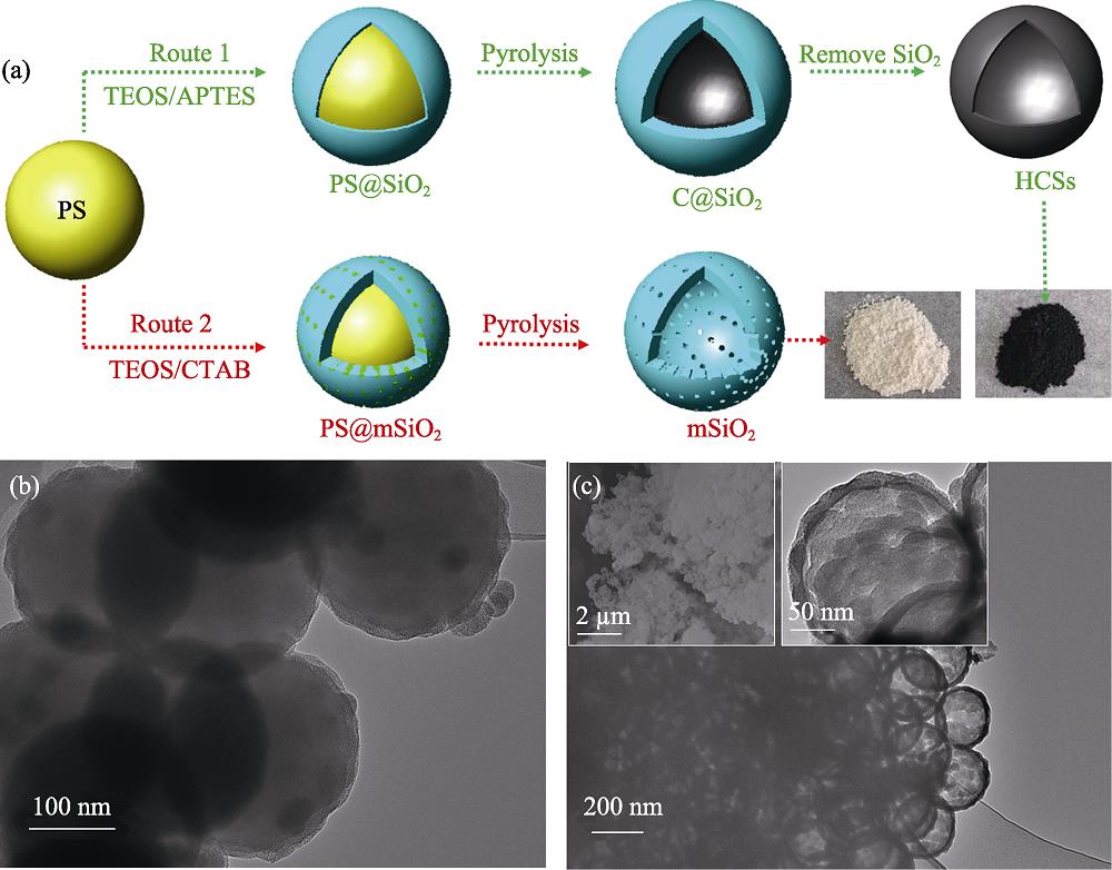
As illustrated in Fig. 1(a), the formation of HCS derived from PS was achieved in the compact silica shell. Briefly, uniform PS spheres were synthesized by using styrene as the precursor and template, then the PS were uniformly coated by a layer of compact silica. During the pyrolysis process, PS spheres transformed into volatile carbonaceous species and deposited in the hermetical silica shell to form a layer of carbon shell. Route 1 in Fig. 1 illustrates the synthesis of dispersible HCS-1, in which the formation of an inorganic outer compact silica shell was crucial. The outer compact silica shell functions as a nanoreactor to provide a confined nanospace for high temperature pyrolysis of the PS polymer[
![]()
Figure .Preparation routes and TEM (b,c) and SEM (c) images
Morphology and structure of obtained samples were characterized by TEM, which showed that highly uniform and monodisperse nanocomposites are successfully obtained (Fig. 2(a)). Each PS@SiO2 core-shell sphere contains only one PS core at the center. It was apparent that each PS sphere was encapsulated by a silica shell with a thickness of approximate 20 nm seeing from the Fig. 2(b). Moreover, a higher resolution TEM image of PS@SiO2 (Fig. 2(c)) exhibited the PS surface was covered with compact SiO2, providing an enclosed space for the encapsulation pyrolysis of PS. Notably, the surface was crude and there was no obvious pores found (the yellow arrow in Fig. 2(c)), attributing to the deposition of silica oligomer particles.
![]()
Figure .TEM images of PS@SiO2 hybrids sphere (a-c) and HCS-1 (d-f)
After deposition of carbon species generated from pyrolysis of the PS and subsequent removal of the compact silica shell, discrete and uniform HCS-1 are produced (Fig. 2(d)). The resulting HCS-1 had a diameter of 190 nm (Fig. 2(c)), which was smaller than that of the PS seed (ca. 200 nm), showing the deposition of decomposed PS happened in the inner encapsulation nanoreactor. In addition, the formation of carbon indicated that the shell was enclosed and thus allowed deposition of carbon species generated from pyrolysis of PS. As shown in Fig. 2(f), the high resolution TEM images of HCS-1 showed the thickness of microporous and amorphous carbon shell with size of 7.5 nm, indicating the irregular deposition of carbon species.
The amount of TEOS is very critical on the structure of HCS. Therefore, we tried to synthesize HCS with different thickness of carbon shell through changing the amount of TEOS. As shown in Fig. 3(a), when the amount of TEOS increased from 1 to 1.5 mL, the HCS-1.5 with more uniform spherical structure was obtained. Notably, the diameter of HCS-1.5 was same with HCS-1 (ca. 190 nm) (Fig. 3(b)), confirming that the carbon species deposition behavior in the inner compact silica shell. Moreover, the shell thickness increased from 7.5 to 13.5 nm (Fig. 3(c)), showing that larger amount of TEOS would play a better encapsulation effect and more carbon residue left.
![]()
Figure .TEM images of HCS-1.5 (a-c) and HCS-0.5 (d-f), the relationship between TEOS amount and HCS thickness (g), and schematic illustration for the pyrolysis deposition of the PS inside the mesoporous silica shell (h) and the silica shell encapsulation nanoreactor (i), TGA analyses of PS and PS@SiO2 samples in N2 (j) and air (k)
In order to further investigate the effect of TEOS amount in this encapsulation pyrolysis, we further reduced the TEOS amount to decrease the shell thickness of HCS. It was clear that the HCS-0.5 possessed mainly spherical morphology with some small fragmentized spheres (the red arrow in Fig. 3(d)). Compared with HCS-1.5, the diameter of HCS-0.5 unchanged and was also ca. 190 nm (Fig. 3(e)), which was the same with that of HCS-1 and HCS-1.5. Furthermore, the high-resolution TEM image in Fig. 3(f) clearly showed the thickness of HCS-0.5 at 4.5 nm, thinner than many other carbon shell derived from resin[
The mechanism of encapsulation pyrolysis synchronous deposition strategy was exhibited in Fig. 3(h, i). During pyrolysis of PS, the volatile carbonaceous species would penetrate through the open pore channel (Fig. 3(h)). Conversely, as shown in Fig. 3(i), when the pyrolysis of PS was confined in a compact silica shell, an increase of temperature results in the intrinsic thermal shrinkage of silica and carbon (char) materials, leading to an increase in density of the outer shell[
The specific textural properties of HCS were studied by N2 adsorption-desorption isotherm (Fig. 4(a)). N2 adsorption-desorption isotherms of HCS with different thickness all exhibited typical type-IV curves hysteresis[
![]()
Figure .N2 adsorption-desorption isotherms (a) and pore distributions (b) of HCS, XRD patterns of HCS-1 (c), XPS spectra of HCS-1 (d), C1s (e) and O1s (f) spectra of HCS-1
X-ray photoelectron spectroscopy (XPS) was performed to further analyze the surface chemical performance of the synthesized HCS-1. As shown in Fig. 4(d), only two peaks were detected in the XPS survey spectra at 284.6 and 532.5 eV, corresponding to C1s, and O1s. There were no other impurities in the HCS-1, indicating the successful deposition of carbon. Quantitative analysis elucidated that the content of C and O was 96.94 and 3.06at%, respectively. The C1s core-level spectrum was divided into three components centering at 284.6, 285.5 and 289.0 eV (Fig. 4(e)), being ascribed to the primary C-C/C=C carbon bonds, residual C-O bonds and C=O bonds formed in the pyrolysis process of PS[
Furthermore, the diameter of HCS could be tuned by varying the size of PS spheres. The scanning electron microscopy (SEM) images in Fig. 5(a-c) showed HCS with diameters of 400, 900 and 1600 nm. As shown in Fig. 5(a), the HCS with diameter of 400 nm possessed uniform and complete spherical morphology. However, with the increasing diameter of PS, the obtained HCS became more and more fragmentary, and broken spheres formed on the surface of the hollow carbon spheres after etching of the silica (Fig. 5(b, c), which might be due to the high pressure with larger diameter of PS sphere in the encapsulation nanoreactor. When the diameter of cavity became large, larger amount of volatile carbonaceous species derived from pyrolysis of PS generated. However, the large compact silica shell was unable to withstand the high pressure, resulting in that those volatile carbonaceous species break through the shell and leading to a fragmentized carbon sphere. N2 adsorption-desorption isotherms were also measured to determine the porous structure of the HCS with different diameter (Fig. 5(d)). Three HCS samples presented a typical IV-type curves, indicating the porous and hollow structures. With the increasing of diameter, the BET surface areas decreased to be 502, 404 and 109 m2·g-1. A wide peak at 20 nm clearly distinguished in the pore size distribution of the HCS (inset in Fig. 5(d)), ascribing to the fragmentary and mesopore formed on the surface of the hollow carbon spheres.
![]()
Figure .SEM images of HCS with dimeter size of 400, 900 and 1600 nm obtained by changing the dimeter of PS (a-c) and N2 adsorption-desorption isotherm (d) and pore distribution (inset) of HCS
Excessive antibiotic use has caused serious environmental pollution in the world. The high surface-to-volume ratios of the hollow carbon show many advantages in treating antibiotic wastewater. Generally, the cavity of the hollow sphere can provide a space for mass storage, thus improving the adsorption capacity of the material. In addition, the thin shell of the hollow sphere can provide convenience for the rapid transmission of substances. Herein, we selected cefalexin as a typical model drug to study the adsorption performance of HCS. Considering the highest specific surface area and favorable translation of thin shell, the HCS-0.5 was selected as typical absorbent for adsorption of cephalexin. The time-resolved adsorption capacities of cefalexin on HCS-1 were shown in Fig. 6(a). Remarkably, the adsorption capacity of activated HCS-1 was ca. 291 mg·g-1. Noticeably, the HCS-1 showed high adsorption in short time, attributing to the developed and directly accessible porosity of these nanosized hollow spheres. Fig. 6(b) shows the equilibrium adsorption curves after adsorption for 24 h. The adsorption capacity of HCS-1 increased with increasing equilibrium concentrations. However, cefalexin could no longer be adsorbed with a certain equilibrium concentration and the highest adsorption capacity of HCS-1 for cefalexin was found to be 293 mg·g-1, which was higher than that of other carbon materials[
![]()
Figure .Adsorption curve of cefalexin over HCS-1 for the contact time (a), various initial concentrations (b), and corresponding Kinetics (c-d) and isothermal (e-f) fittings
The kinetic and isotherm models were also used to elucidate the adsorption process. The pseudo-first-order kinetics and pseudo-second-order kinetics models were used to test the correlation between the adsorption rate and equilibrium time. The adsorption kinetic plots and the predicted kinetic parameters were presented in Fig. 6(c, d). As observed, the pseudo-second-order kinetics model was more suitable for cefalexin adsorption due to its higher regression coefficient (R2=0.9991). The adsorption process was likely to occur on the surface of materials and would last until the surface sites were completely occupied. In addition, the study on adsorption equilibrium was performed for HCS-1. The Freundlich sorption model (Fig. 6(e)), represented by an empirical equation, was not good (R2=0.6999). This indicated that adsorption of cefalexin on HCS-1 was not heterogeneous adsorption. However, the obtained regression coefficient by Langmuir model was 0.9999 (Fig. 6(f)), indicating the adsorption isotherm fitted Langmuir model well. The maximum theoretical adsorption capacity calculated by Langmuir model was 273 mg·g-1, which was approximately in close agreement with the measured data, illustrating that the adsorbed cefalexin formed a monolayer coverage on the adsorbent surface and all adsorption sites possessed equal, uniform adsorption energies. Therefore, the pseudo-second-order kinetics and Langmuir isotherms model can well describe the adsorption behavior of HCS-1.
3. Conclusion
To summarize, we have demonstrated a novel and efficient encapsulation pyrolysis synchronous deposition method to prepare HCS with tailorable particle size and well controlled thickness of carbon shell. We confirmed that the encapsulation nanoreactor, made by hermetical silica shell, could successfully provide nanospace for deposition of volatile carbonaceous species derived from pyrolysis of PS. The diameter of HCS and thickness of carbon shell could be tuned by changing the size of PS and amount of TEOS, respectively. The obtained HCS showed uniform spherical morphology with diameter from 200 to 1600 nm and different thickness of carbon shell (4.5-13.5 nm). The HCS exhibited a good performance for treatment of antibiotic waste water. In addition, this encapsulation pyrolysis synchronous deposition strategy may also be applied for the preparation of HCS using other easily decomposing polymer, e.g., polyethylene, polyvinyl alcohol and polyacrylonitrile.
References
[2] D LI, C FENG, K LIU H et al. Hollow carbon spheres with encapsulated germanium as an anode material for lithium ion batteries. J. Mater. Chem. A, 3, 978-981(2015).
[8] C ZOU, D WU, M LI et al. Template-free fabrication of hierarchical porous carbon by constructing carbonyl crosslinking bridges between polystyrene chains. J. Mater. Chem., 20, 731-735(2010).
[9] A CHEN, Y LI, Y YU et al. Synthesis of hollow mesoporous carbon spheres via “dissolution-capture” method for effective phenol adsorption. Carbon, 103, 157-162(2016).
[11] F HU, H YANG, C WANG et al. Co-N-doped mesoporous carbon hollow spheres as highly efficient electrocatalysts for oxygen reduction reaction Small, 13, 1602507(2017).
[14] A CHEN, Y YU, H LV et al. Thin-walled, mesoporous and nitrogen-doped hollow carbon spheres using ionic liquids as precursors. J. Mater. Chem. A, 1, 1045-1047(2013).
[17] G ZHOU, N-R KIM, S-E CHUN et al. Highly porous and easy shapeable poly-dopamine derived graphene-coated single walled carbon nanotube aerogels for stretchable wire-type supercapacitors. Carbon, 130, 137-144(2018).
[18] J CHONG, X ZHU, W HUANG et al. The fabrication of size-tunable nitrogen-doped dual-mesoporous carbon nanospheres with excellent thermal stability via colloidal silica driving co-assembly strategy. Carbon, 126, 156-164(2018).
[19] G ZHANG, J WANG, B QIN et al. Room-temperature rapid synthesis of metal-free doped carbon materials. Carbon, 115, 28-33(2017).


Set citation alerts for the article
Please enter your email address

© Copyright 2018-2021 | Chinese Laser Press. All Rights Reserved 沪ICP备15018463号-20