• Laser & Optoelectronics Progress
  • Vol. 55, Issue 1, 11403 (2018)
Li Junfeng, Wei Zhengying*, and Lu Bingheng
Author Affiliations
  • State Key Laboratory for Manufacturing Systems Engineering, Xi''an Jiaotong University, Shaanxi, Xi''an 710049, China
  • show less
    DOI: 10.3788/LOP55.011403 Cite this Article Set citation alerts
    Li Junfeng, Wei Zhengying, Lu Bingheng. Research Progress on Technology of Selective Laser Melting of Titanium and Titanium Alloys[J]. Laser & Optoelectronics Progress, 2018, 55(1): 11403 Copy Citation Text show less
    Schematic of SLM technology
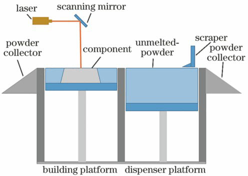
    Fig. 1. Schematic of SLM technology
    Cross-sectional images of Ti components formed by SLM under different scanning speeds. (a) 100 mm·s-1; (b) 200 mm·s-1; (c) 300 mm·s-1; (d) 400 mm·s-128<
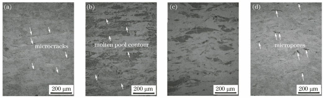
    Fig. 2. Cross-sectional images of Ti components formed by SLM under different scanning speeds. (a) 100 mm·s-1; (b) 200 mm·s-1; (c) 300 mm·s-1; (d) 400 mm·s-128<
    XRD spectra of Ti components formed by SLM under different diffraction angles. (a) 2θ=38.45°; (b) 2θ=40.18°[28]
    Fig. 3. XRD spectra of Ti components formed by SLM under different diffraction angles. (a) 2θ=38.45°; (b) 2θ=40.18°[28]
    Microstructures of Ti components formed by SLM under different scanning speeds. (a) 100 mm·s-1; (b) 200 mm·s-1; (c) 300 mm·s-1; (d) 400 mm·s-128<
    Fig. 4. Microstructures of Ti components formed by SLM under different scanning speeds. (a) 100 mm·s-1; (b) 200 mm·s-1; (c) 300 mm·s-1; (d) 400 mm·s-128<
    Microstructures of CP-Ti samples formed by SLM (a)(b) without and (c)(d) with SMF
    Fig. 5. Microstructures of CP-Ti samples formed by SLM (a)(b) without and (c)(d) with SMF
    (a)(b) Optical microscopy images, (c)(d)scanning electron microscopy images, (e)(f) orientation maps and (g)(h) inverse pole figures of fracture section under different conditions[31]
    Fig. 6. (a)(b) Optical microscopy images, (c)(d)scanning electron microscopy images, (e)(f) orientation maps and (g)(h) inverse pole figures of fracture section under different conditions[31]
    Morphologies of Ti6Al4V powder. (a) 500×; (b) 3000×
    Fig. 7. Morphologies of Ti6Al4V powder. (a) 500×; (b) 3000×
    Melting and solidification processes under different laser scanning speeds[43]. (a) 5 mm·s-1; (b) 10 mm·s-1; (c) 25 mm·s-1; (d) 50 mm·s-1; (e) 100 mm·s-1
    Fig. 8. Melting and solidification processes under different laser scanning speeds[43]. (a) 5 mm·s-1; (b) 10 mm·s-1; (c) 25 mm·s-1; (d) 50 mm·s-1; (e) 100 mm·s-1
    Influence of scanning strategy on microstructures[53]. (a)(b)(c)(d) Unidirectional scanning; (e)(f)(g)(h) cross scanning
    Fig. 9. Influence of scanning strategy on microstructures[53]. (a)(b)(c)(d) Unidirectional scanning; (e)(f)(g)(h) cross scanning
    Microstructures of Ti6Al4V specimens formed by SLM with laser energy input of (a) 0.5E0, (b) E0 and (c) 2E054</mtr
    Fig. 10. Microstructures of Ti6Al4V specimens formed by SLM with laser energy input of (a) 0.5E0, (b) E0 and (c) 2E054
    (a) Schematic of support structure; (b) schematic of support structure with As/Ap=0.25[63]
    Fig. 11. (a) Schematic of support structure; (b) schematic of support structure with As/Ap=0.25[63]
    Microstructures of Ti6Al4V components formed by SLM [63]. (a) As/Ap=0.125; (b) As/Ap=0.25; (c) As/Ap=0.4; (d) As/Ap=1
    Fig. 12. Microstructures of Ti6Al4V components formed by SLM [63]. (a) As/Ap=0.125; (b) As/Ap=0.25; (c) As/Ap=0.4; (d) As/Ap=1
    Structural components fabricated by SLM. (a) CP-Ti; (b) TiTa
    Fig. 13. Structural components fabricated by SLM. (a) CP-Ti; (b) TiTa
    (a) Individual bone plate after surface treatment; (b) matching between bone plate and pelvic model
    Fig. 14. (a) Individual bone plate after surface treatment; (b) matching between bone plate and pelvic model
    (a) Formed part and (b) model of gradient fusion cage section
    Fig. 15. (a) Formed part and (b) model of gradient fusion cage section
    Ti6Al4V sound absorbers fabricated by SLM. (a) Sample A; (b) sample B
    Fig. 16. Ti6Al4V sound absorbers fabricated by SLM. (a) Sample A; (b) sample B
    Samples on substrate
    Fig. 17. Samples on substrate
    Titanium alloy parts fabricated by SLM
    Fig. 18. Titanium alloy parts fabricated by SLM
    SLM equipmentσUTS /MPaσ0.2 /MPaε /%Hardness /HVReference
    MTTSLM 250 HL757±12.5555±319.5±1.8261[29]
    MCPSLM 250766-28-[31]
    SMF-MCPSLM 250794-35-
    SLM prototype65050017-[32]
    Table 1. Mechanical properties of CP-Ti fabricated by different SLM equipments
    Conditionσ0.2 /MPaσUTS /MPaεfracture /%Ref
    540 ℃ for 2 h, water cooling1118±391223±525.36±2.02[65]
    850 ℃ for 2 h, furnace cooling955±61004±612.84±1.36[65]
    850 ℃ for 5 h, furnace cooling909±24965±20Pre-fracture[65]
    1015 ℃ for 0.5 h, air cooling followed by843 ℃ for 2 h, furnace cooling801±20874±2313.45±1.18[65]
    1020 ℃ for 2 h, air cooling760±19840±2714.06±2.53[65]
    705 ℃ for 3 h, air cooling1026±351082±349.04±2.03[65]
    940 ℃ for 1 h and 650 ℃ for 2 h, air cooling899±27948±2713.59±0.32[65]
    1015 ℃ for 0.5 h and 730 ℃ for 2 h, air cooling822±25902±1912.74±0.56[65]
    SLM built(no post treatment)1110±91267±57.28±1.12[65]
    SLM built (no post treatment)-13513.14[66]
    600 ℃ for 2 h, furnace cooling-12873.2[66]
    750 ℃ for 2 h, furnace cooling-11853.4[66]
    925 ℃ for 2 h, furnace cooling-98812.2[66]
    1050 ℃ for 2 h, furnace cooling-9809.2[66]
    700 ℃ for 1 h, cooling at 10 K·s-11051111511.3[67]
    900 ℃ for 2 h, and 700 ℃ for 1 h, cooling at 10 K·s-19089889.5[67]
    Hot isostatic pressing (900 ℃, 100 MPa) for 2 hand 700 ℃ for 1 h cooling at 10 K·s-188597319.0[67]
    SLM built (no post treatment)736105111.9[67]
    SLM built (no post treatment)990±51095±108.1±03[61]
    Hot worked and annealed790±20870±1018.1±0.8[61]
    SLM built (no post treatment)1250-12801390-14305.5-7.0[68]
    (705±20) ℃ for 1.5 h, air cooling1080-11001110-113011.0-13.0[68]
    650 ℃ for 4 h, furnace cooling1145±171187±107±2.7[69]
    890 ℃ for 2 h, furnace cooling973±8996±103±0.4[69]
    SLM built (no post treatment)1125±2212.16±86±0.4[69]
    SLM built (no post treatment)1015109010[70]
    Hot isostatic pressing85096014[70]
    730 ℃ for 2 h, furnace cooling974±71065±217.0±0.5[71]
    SLM built (no post treatment)1075±251199±497.6±0.5[71]
    Table 2. Mechanical properties of Ti6Al4V components formed by SLM under different process conditions
    Li Junfeng, Wei Zhengying, Lu Bingheng. Research Progress on Technology of Selective Laser Melting of Titanium and Titanium Alloys[J]. Laser & Optoelectronics Progress, 2018, 55(1): 11403
    Download Citation