• Photonics Research
  • Vol. 8, Issue 11, 1757 (2020)
Kathirvel Nallappan1、2、4、*, Yang Cao2, Guofu Xu2, Hichem Guerboukha2、3, Chahé Nerguizian1, and Maksim Skorobogatiy2、5、*
Author Affiliations
  • 1Department of Electrical Engineering, Polytechnique Montréal, Montréal, Québec H3T1J4, Canada
  • 2Department of Engineering Physics, Polytechnique Montréal, Montréal, Québec H3T1J4, Canada
  • 3School of Engineering, Brown University, Providence, Rhode Island 02912, USA
  • 4e-mail: kathirvel.nallappan@polymtl.ca
  • 5e-mail: maksim.skorobogatiy@polymtl.ca
  • show less
    DOI: 10.1364/PRJ.396433 Cite this Article Set citation alerts
    Kathirvel Nallappan, Yang Cao, Guofu Xu, Hichem Guerboukha, Chahé Nerguizian, Maksim Skorobogatiy. Dispersion-limited versus power-limited terahertz communication links using solid core subwavelength dielectric fibers[J]. Photonics Research, 2020, 8(11): 1757 Copy Citation Text show less
    Schematic of the THz wireless and fiber communication links for reliable and versatile intra-/inter-vehicle communication applications.
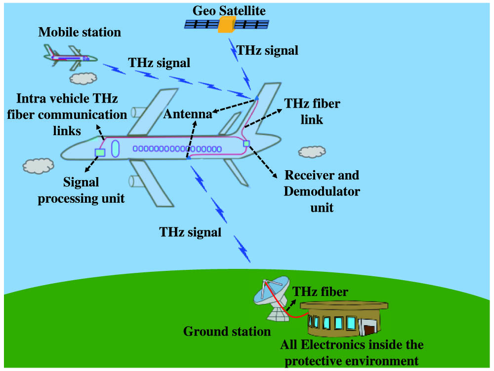
    Fig. 1. Schematic of the THz wireless and fiber communication links for reliable and versatile intra-/inter-vehicle communication applications.
    (a) Schematic of the rod-in-foam subwavelength THz fiber. Fiber outer diameter is chosen to accommodate ∼90% of the power guided by the identical rod-in-foam waveguide with infinite cladding. (b) Photograph of the rod-in-foam fiber.
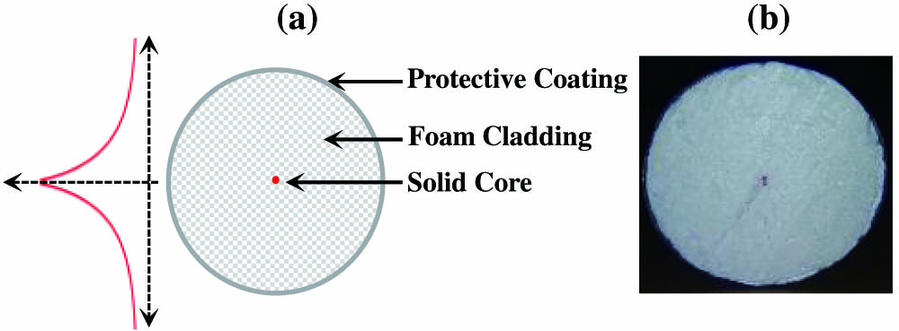
    Fig. 2. (a) Schematic of the rod-in-foam subwavelength THz fiber. Fiber outer diameter is chosen to accommodate 90% of the power guided by the identical rod-in-foam waveguide with infinite cladding. (b) Photograph of the rod-in-foam fiber.
    Normalized electric field profile |E| of the fundamental mode at the carrier frequency of 128 GHz: (a) 1.75 mm fiber, (b) 0.93 mm fiber, and (c) 0.57 mm fiber. (d) The power fraction of the fundamental mode within the aperture of a variable diameter. (e) The effective refractive indices of the guided modes, and (f) the corresponding modal absorption losses for the rod-in-air fibers of different diameters at the carrier frequency of 128 GHz. As a reference, the bulk refractive index and absorption loss of the fiber polypropylene core are 1.485 and 2.36 dB/m, respectively, at 128 GHz.
    Fig. 3. Normalized electric field profile |E| of the fundamental mode at the carrier frequency of 128 GHz: (a) 1.75 mm fiber, (b) 0.93 mm fiber, and (c) 0.57 mm fiber. (d) The power fraction of the fundamental mode within the aperture of a variable diameter. (e) The effective refractive indices of the guided modes, and (f) the corresponding modal absorption losses for the rod-in-air fibers of different diameters at the carrier frequency of 128 GHz. As a reference, the bulk refractive index and absorption loss of the fiber polypropylene core are 1.485 and 2.36 dB/m, respectively, at 128 GHz.
    Excitation efficiency by power of the fundamental HE11 mode of a rod-in-air fiber of three different diameters. (a) Excitation efficiency versus Gaussian beam diameter. (b) Excitation efficiency as a function of frequency for the optimized Gaussian beam diameter. Inset in (a), schematic of a simple free space coupler.
    Fig. 4. Excitation efficiency by power of the fundamental HE11 mode of a rod-in-air fiber of three different diameters. (a) Excitation efficiency versus Gaussian beam diameter. (b) Excitation efficiency as a function of frequency for the optimized Gaussian beam diameter. Inset in (a), schematic of a simple free space coupler.
    Power budget considerations for the fiber links of variable distance and 6 Gbps data transmission rate used in our experiments. Transmitter THz power is −6.6 dBm (∼218 μW). The signal loss level for the error-free data transmission is experimentally found at −20 dBm, and the absolute noise floor is −34 dBm.
    Fig. 5. Power budget considerations for the fiber links of variable distance and 6 Gbps data transmission rate used in our experiments. Transmitter THz power is −6.6 dBm (218  μW). The signal loss level for the error-free data transmission is experimentally found at 20  dBm, and the absolute noise floor is 34  dBm.
    (a) Bending losses of the 1.75 mm, 0.93 mm, and 0.57 mm fibers for different bending radii and polarizations. The solid curve corresponds to the X-polarized leaky mode, and the dashed curve corresponds to the Y-polarization leaky mode of a bend modeled using COMSOL software. The dotted lines correspond to the analytical estimations of the bending loss given by Eq. (3). (b) The group velocity dispersion of the fundamental X-polarized leaky mode of the 1.75 mm fiber as a function of the bending radius. (c) The field distributions correspond to those of the bent leaky modes for fibers of different diameters and bending radius of 3 cm.
    Fig. 6. (a) Bending losses of the 1.75 mm, 0.93 mm, and 0.57 mm fibers for different bending radii and polarizations. The solid curve corresponds to the X-polarized leaky mode, and the dashed curve corresponds to the Y-polarization leaky mode of a bend modeled using COMSOL software. The dotted lines correspond to the analytical estimations of the bending loss given by Eq. (3). (b) The group velocity dispersion of the fundamental X-polarized leaky mode of the 1.75 mm fiber as a function of the bending radius. (c) The field distributions correspond to those of the bent leaky modes for fibers of different diameters and bending radius of 3 cm.
    (a) Second-order dispersion β2 of the fundamental mode for 1.75 mm, 0.93 mm, and 0.57 mm fibers. The dashed vertical line corresponds to the single mode cutoff frequency of respective fibers. (b) The maximum bit rate supported by the fibers in a 10 m link with zero modal loss.
    Fig. 7. (a) Second-order dispersion β2 of the fundamental mode for 1.75 mm, 0.93 mm, and 0.57 mm fibers. The dashed vertical line corresponds to the single mode cutoff frequency of respective fibers. (b) The maximum bit rate supported by the fibers in a 10 m link with zero modal loss.
    (a) Schematic of the photonics-based THz communication system. Inset, butt coupling of the THz fiber with the horn antenna using fisherman’s knot assembly. (b) Photograph of the 6-m-long 1.75 mm diameter rod-in-air fiber THz communication link.
    Fig. 8. (a) Schematic of the photonics-based THz communication system. Inset, butt coupling of the THz fiber with the horn antenna using fisherman’s knot assembly. (b) Photograph of the 6-m-long 1.75 mm diameter rod-in-air fiber THz communication link.
    Measuring propagation losses of a 1.75 mm fiber using cutback technique. (a) Measured eye amplitude for 1 Gbps, 3 Gbps, and 6 Gbps signals as a function of the fiber length. (b) Power loss estimation using detector pre-calibration and recorded eye amplitude.
    Fig. 9. Measuring propagation losses of a 1.75 mm fiber using cutback technique. (a) Measured eye amplitude for 1 Gbps, 3 Gbps, and 6 Gbps signals as a function of the fiber length. (b) Power loss estimation using detector pre-calibration and recorded eye amplitude.
    (a) Fraction of the modal power inside the aperture of a variable diameter. Inset, circular aperture centered around the rod-in-air fiber. Photograph of the THz subwavelength fibers with polystyrene foam cladding: (b) 1.75 mm fiber with 5 mm diameter foam cladding (100% of power); (c) 0.93 mm fiber with 6 mm diameter foam cladding (90% of power); (d) 0.57 mm fiber with 45 mm diameter foam cladding (90% of power).
    Fig. 10. (a) Fraction of the modal power inside the aperture of a variable diameter. Inset, circular aperture centered around the rod-in-air fiber. Photograph of the THz subwavelength fibers with polystyrene foam cladding: (b) 1.75 mm fiber with 5 mm diameter foam cladding (100% of power); (c) 0.93 mm fiber with 6 mm diameter foam cladding (90% of power); (d) 0.57 mm fiber with 45 mm diameter foam cladding (90% of power).
    Measured BER versus bit rate for the 1.75 mm and 0.93 mm fibers, and the link length of 8 m. Inset, eye patterns for the two fibers at various bit rates.
    Fig. 11. Measured BER versus bit rate for the 1.75 mm and 0.93 mm fibers, and the link length of 8 m. Inset, eye patterns for the two fibers at various bit rates.
    Measured BER versus bit rate for the 0.57 mm fiber and the link length of 10 m. Inset, eye patterns for 1, 2, and 6 Gbps bit rates.
    Fig. 12. Measured BER versus bit rate for the 0.57 mm fiber and the link length of 10 m. Inset, eye patterns for 1, 2, and 6 Gbps bit rates.
    Measured BER for the 90° bending of 1.75 mm fiber with the bending radius of 6.5 cm versus bit rate. The schematic and experimental setup of the bent fiber are shown in the inset.
    Fig. 13. Measured BER for the 90° bending of 1.75 mm fiber with the bending radius of 6.5 cm versus bit rate. The schematic and experimental setup of the bent fiber are shown in the inset.
    Comparison between free space and rod-in-air fiber (straight)-based THz communication links at 128 GHz carrier frequency. The emitter power is set at 0 dBm.
    Fig. 14. Comparison between free space and rod-in-air fiber (straight)-based THz communication links at 128 GHz carrier frequency. The emitter power is set at 0 dBm.
    Schematic of the CW THz spectroscopy system for RI measurements.
    Fig. 15. Schematic of the CW THz spectroscopy system for RI measurements.
    (a) Unwrapped phase for different PP slab thicknesses. (b) Refractive index of the PP fiber as a function of frequency.
    Fig. 16. (a) Unwrapped phase for different PP slab thicknesses. (b) Refractive index of the PP fiber as a function of frequency.
    (a) THz photocurrent for different fiber lengths. (b) Absorption loss of the 1.75 mm PP fiber (blue) as well as inferred bulk absorption loss (black) and a corresponding square fit (red).
    Fig. 17. (a) THz photocurrent for different fiber lengths. (b) Absorption loss of the 1.75 mm PP fiber (blue) as well as inferred bulk absorption loss (black) and a corresponding square fit (red).
    (a) THz output power from the photomixer versus frequency and (b) developed DC voltage in the detector corresponding to the input THz power shown in (a).
    Fig. 18. (a) THz output power from the photomixer versus frequency and (b) developed DC voltage in the detector corresponding to the input THz power shown in (a).
    (a) Measured THz power and (b) developed DC voltage in the ZBD at the frequency of 128 GHz by varying the input infrared optical power. (c) Developed DC voltage in the ZBD versus THz power at the frequency of 128 GHz. (d) Relation between the developed DC voltage from the ZBD for the coupled THz signal, eye amplitude, and digital one level of the 1 Gbps eye pattern at the carrier frequency of 128 GHz.
    Fig. 19. (a) Measured THz power and (b) developed DC voltage in the ZBD at the frequency of 128 GHz by varying the input infrared optical power. (c) Developed DC voltage in the ZBD versus THz power at the frequency of 128 GHz. (d) Relation between the developed DC voltage from the ZBD for the coupled THz signal, eye amplitude, and digital one level of the 1 Gbps eye pattern at the carrier frequency of 128 GHz.
    BER measurement in our communication system as a function of the received signal power for the bit rate of 6 Gbps.
    Fig. 20. BER measurement in our communication system as a function of the received signal power for the bit rate of 6 Gbps.
    Eye pattern of 6 Gbps data for the emitter power of (a) 0.8 μW (−30.96 dBm), (b) 0.6 μW (−32.21 dBm), and 0.4 μW (−33.97 dBm).
    Fig. 21. Eye pattern of 6 Gbps data for the emitter power of (a) 0.8 μW (30.96  dBm), (b) 0.6 μW (32.21  dBm), and 0.4 μW (33.97  dBm).
    Normalized electric field profiles |E| of the fundamental modes at the carrier frequency of 128 GHz for rod-in-foam fibers of various diameters. (a) 1.75-mm-diameter core and 5-mm-diameter foam cladding; (b) 0.93-mm-diameter core and 7-mm-diameter foam cladding; (c) 0.57-mm-diameter core and 50-mm-diameter foam cladding.
    Fig. 22. Normalized electric field profiles |E| of the fundamental modes at the carrier frequency of 128 GHz for rod-in-foam fibers of various diameters. (a) 1.75-mm-diameter core and 5-mm-diameter foam cladding; (b) 0.93-mm-diameter core and 7-mm-diameter foam cladding; (c) 0.57-mm-diameter core and 50-mm-diameter foam cladding.
    THz FiberMaximum Excitation Efficiency, CGaussian Beam Diameter
    1.75 mm fiber0.971.85 mm
    0.93 mm fiber0.963.2 mm
    0.57 mm fiber0.9032.7 mm
    Table 1. Maximum Excitation Efficiency and Its Corresponding Gaussian Beam Size for the Fibers of Different Diameters
    THz FiberZero Dispersion Frequency (ZDF)Bit Rate at ZDF for a 10 m Link
    1.75 mm fiber128 GHz9 Gbps
    0.93 mm fiber241 GHz13.8 Gbps
    0.57 mm fiber393.5 GHz19.2 Gbps
    Table 2. ZDF for 1.75 mm, 0.93 mm, and 0.57 mm Fibers and Their Maximal Supported Bit Rates Estimated Using Third-Order Dispersion
    Link Distance, L8 m15 m30 m
    Maximal bit rate in Gbps for different link distances; carrier frequency is 128 GHzFree space560410290
    1.75 mm fiber10.58.46.7
    0.93 mm fiber1.310.7
    0.57 mm fiber5.23.82.7
    Required transmitter power in dBm so that the received signal power is above the minimal 20  dBm level required for the 6 Gbps error-free transmissionFree space (DTX=DRX=10.8  mm, α=6.5  dB/km)26.331.837.9
    Free space (DTX=DRX=50.8  mm, α=6.5  dB/km)−0.574.911.0
    1.75 mm fiber, α=2.2  dB/m, C=0.97−2.113.246.1
    0.93 mm fiber, α=0.62  dB/m, C=0.96−14.6−10.3−0.9
    0.57 mm fiber, α=0.01  dB/m, C=0.90−19.0−18.9−18.8
    Table 3. Maximal Bit Rate (ASK Modulation) at Different Link Distances and Required Emitter Power to Result in the 20  dBm Signal Power (Error-Free Transmission) at the Receiver End for Both Free Space and Fiber Communication Linksa
    Kathirvel Nallappan, Yang Cao, Guofu Xu, Hichem Guerboukha, Chahé Nerguizian, Maksim Skorobogatiy. Dispersion-limited versus power-limited terahertz communication links using solid core subwavelength dielectric fibers[J]. Photonics Research, 2020, 8(11): 1757
    Download Citation