• Opto-Electronic Advances
  • Vol. 5, Issue 3, 210026 (2022)
Yanxiang Zhang1、†, Xiaofei Liu2、†, Han Lin3, Dan Wang1, Ensi Cao1, Shaoding Liu1, Zhongquan Nie1、*, and Baohua Jia3、*
Author Affiliations
  • 1Key Lab of Advanced Transducers and Intelligent Control System, Ministry of Education and Shanxi Province, College of Physics and Optoelectronics, Taiyuan University of Technology, Taiyuan 030024, China
  • 2Department of Physics, Harbin Institute of Technology, Harbin 150001, China
  • 3Centre of Translational Atomaterials (CTAM), Faculty of Science, Engineering and Technology, Swinburne University of Technology, Hawthorn, VIC 3122, Australia
  • show less
    DOI: 10.29026/oea.2022.210026 Cite this Article
    Yanxiang Zhang, Xiaofei Liu, Han Lin, Dan Wang, Ensi Cao, Shaoding Liu, Zhongquan Nie, Baohua Jia. Ultrafast multi-target control of tightly focused light fields[J]. Opto-Electronic Advances, 2022, 5(3): 210026 Copy Citation Text show less
    The conceptual schematic to yield ultrafast multi-target light fields in a single high NA objective focusing configuration. Right inset in black area represents the light fields with three sorts of patterned conversions as time elapses. Therein, the first row denotes the bright-dark alternative optical field especially for the radially polarized beam illumination; the second row shows periodic rotational light field actuated by arbitrary polarizations; the third row stands for reciprocal conversion between different polarized field components. LP: linear polarization; RP: radial polarization; AP: azimuthal polarization; SPP: spiral phase plate; TS: time sequence; OV: optical vortex; OL: objective lens.
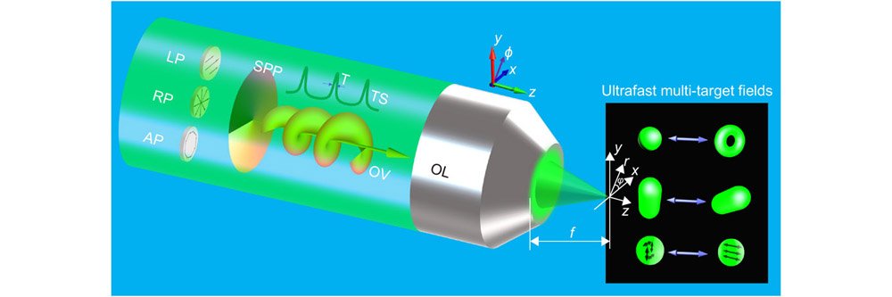
    Fig. 1. The conceptual schematic to yield ultrafast multi-target light fields in a single high NA objective focusing configuration. Right inset in black area represents the light fields with three sorts of patterned conversions as time elapses. Therein, the first row denotes the bright-dark alternative optical field especially for the radially polarized beam illumination; the second row shows periodic rotational light field actuated by arbitrary polarizations; the third row stands for reciprocal conversion between different polarized field components. LP: linear polarization; RP: radial polarization; AP: azimuthal polarization; SPP: spiral phase plate; TS: time sequence; OV: optical vortex; OL: objective lens.
    The focused field distributions of linearly polarized light with the first-order vortex at different temporal intervals. The total intensity distributions |Et|2 (a1–a8) as well as the transverse |Ex|2 (b1–b8), |Ey|2 (c1–c8) and the longitudinal |Ez|2 (d1–d8) field components in the x-y plane with the periodic time of t = 0 fs (a1–d1), 50 fs (a2–d2), 100 fs (a3–d3), 150 fs (a4–d4), 200 fs (a5–d5), 250 fs (a6–d6), 300 fs (a7–d7), and 350 fs (a8–d8). The color scale indicates the magnitude of the normalized intensity. The sizes for all of the images are 2λ×2λ. The other parameters are chosen as pulse width T = 5 fs, a laser beam with a center wavelength of 532 nm, central angular frequency ω0 = 3.543×10¹⁵ s–1, beam size σ0 = 2 cm, topological charge m = 1, and NA = 0.9.
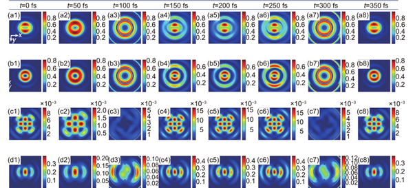
    Fig. 2. The focused field distributions of linearly polarized light with the first-order vortex at different temporal intervals. The total intensity distributions |Et|2 (a1a8) as well as the transverse |Ex|2 (b1b8), |Ey|2 (c1c8) and the longitudinal |Ez|2 (d1d8) field components in the x-y plane with the periodic time of t = 0 fs (a1–d1), 50 fs (a2–d2), 100 fs (a3–d3), 150 fs (a4–d4), 200 fs (a5–d5), 250 fs (a6–d6), 300 fs (a7–d7), and 350 fs (a8–d8). The color scale indicates the magnitude of the normalized intensity. The sizes for all of the images are 2λ×2λ. The other parameters are chosen as pulse width T = 5 fs, a laser beam with a center wavelength of 532 nm, central angular frequency ω0 = 3.543×10¹⁵ s–1, beam size σ0 = 2 cm, topological charge m = 1, and NA = 0.9.
    The focused field distributions of radially polarized light with the first-order vortex at different temporal intervals. The total intensity distributions |Et|2 (a1–a8) as well as the transverse |Ex|2 (b1–b8), |Ey|2 (c1–c8) and the longitudinal |Ez|2 (d1–d8) field components in the x−y plane with the periodic time of t = 0 fs (a1–d1), 50 fs (a2–d2), 100 fs (a3–d3), 150 fs (a4–d4), 200 fs (a5–d5), 250 fs (a6–d6), 300 fs (a7–d7), and 350 fs (a8–d8), respectively. Parameters are the same as those in Fig. 2.
    Fig. 3. The focused field distributions of radially polarized light with the first-order vortex at different temporal intervals. The total intensity distributions |Et|2 (a1a8) as well as the transverse |Ex|2 (b1b8), |Ey|2 (c1c8) and the longitudinal |Ez|2 (d1d8) field components in the x−y plane with the periodic time of t = 0 fs (a1–d1), 50 fs (a2–d2), 100 fs (a3–d3), 150 fs (a4–d4), 200 fs (a5–d5), 250 fs (a6–d6), 300 fs (a7–d7), and 350 fs (a8–d8), respectively. Parameters are the same as those in Fig. 2.
    A phase gallery of tightly focused radially polarized light with the first-order vortex at different temporal intervals. The phase distributions of the transverse |Ex|2 (a1–a8), |Ey|2 (b1–b8) and the longitudinal |Ez|2 (c1–c8) in the x−y plane with the time of t = 0 fs (a1–c1), 50 fs (a2–c2), 100 fs (a3–c3), 150 fs (a4–c4), 200 fs (a5–c5), 250 fs (a6–c6), 300 fs (a7–c7), and 350 fs (a8–c8), respectively. The white circles denote the rotational phases. The color scale indicates the magnitude of the phase. The sizes for all of the images are 2λ×2λ. Parameters are the same as those in Fig. 2.
    Fig. 4. A phase gallery of tightly focused radially polarized light with the first-order vortex at different temporal intervals. The phase distributions of the transverse |Ex|2 (a1a8), |Ey|2 (b1b8) and the longitudinal |Ez|2 (c1c8) in the x−y plane with the time of t = 0 fs (a1–c1), 50 fs (a2–c2), 100 fs (a3–c3), 150 fs (a4–c4), 200 fs (a5–c5), 250 fs (a6–c6), 300 fs (a7c7), and 350 fs (a8–c8), respectively. The white circles denote the rotational phases. The color scale indicates the magnitude of the phase. The sizes for all of the images are 2λ×2λ. Parameters are the same as those in Fig. 2.
    Normalized Poynting vector fields along the propagating direction (the first row) and on the focal plane (the second to last rows) of the tightly focused radially polarized light with the first-order vortex at different temporal intervals when t = 0 fs, 100 fs, 200 fs, 300 fs, and 400 fs, respectively.The total Poynting vector fields St (the first row and the second row); radial Poynting vector fields Sr (the third row) and azimuthal Poynting vector fields Sφ (the fourth row) as well as longitudinal Poynting vector fields Sz (the last row). Parameters are the same as those in Fig. 2.
    Fig. 5. Normalized Poynting vector fields along the propagating direction (the first row) and on the focal plane (the second to last rows) of the tightly focused radially polarized light with the first-order vortex at different temporal intervals when t = 0 fs, 100 fs, 200 fs, 300 fs, and 400 fs, respectively.The total Poynting vector fields St (the first row and the second row); radial Poynting vector fields Sr (the third row) and azimuthal Poynting vector fields Sφ (the fourth row) as well as longitudinal Poynting vector fields Sz (the last row). Parameters are the same as those in Fig. 2.
    Ultrafast multi-target control of the focal light fields for the radially polarized light illumination. (a) and (b) the intensity distributions of the total focal field along the x and the z axes at different temporal intervals with t = 0 fs, 100 fs, 113 fs, 150 fs. (c) the rotational angles of the x/y field components (overlapped) as time elapses. (d) the normalized intensity curves of transverse (overlapped black solid line and red dotted line) and longitudinal field components (blue solid line) as a function of time during 0–400 fs.
    Fig. 6. Ultrafast multi-target control of the focal light fields for the radially polarized light illumination. (a) and (b) the intensity distributions of the total focal field along the x and the z axes at different temporal intervals with t = 0 fs, 100 fs, 113 fs, 150 fs. (c) the rotational angles of the x/y field components (overlapped) as time elapses. (d) the normalized intensity curves of transverse (overlapped black solid line and red dotted line) and longitudinal field components (blue solid line) as a function of time during 0–400 fs.
    Yanxiang Zhang, Xiaofei Liu, Han Lin, Dan Wang, Ensi Cao, Shaoding Liu, Zhongquan Nie, Baohua Jia. Ultrafast multi-target control of tightly focused light fields[J]. Opto-Electronic Advances, 2022, 5(3): 210026
    Download Citation