1Key Lab of Advanced Transducers and Intelligent Control System, Ministry of Education and Shanxi Province, College of Physics and Optoelectronics, Taiyuan University of Technology, Taiyuan 030024, China
2Department of Physics, Harbin Institute of Technology, Harbin 150001, China
3Centre of Translational Atomaterials (CTAM), Faculty of Science, Engineering and Technology, Swinburne University of Technology, Hawthorn, VIC 3122, Australia
Yanxiang Zhang, Xiaofei Liu, Han Lin, Dan Wang, Ensi Cao, Shaoding Liu, Zhongquan Nie, Baohua Jia. Ultrafast multi-target control of tightly focused light fields[J]. Opto-Electronic Advances, 2022, 5(3): 210026
Copy Citation Text
The control of ultrafast optical field is of great interest in developing ultrafast optics as well as the investigation on various light-matter interactions with ultrashort pulses. However, conventional spatial encoding approaches have only limited steerable targets usually neglecting the temporal effect, thus hindering their broad applications. Here we present a new concept for realizing ultrafast modulation of multi-target focal fields based on the facile combination of time-dependent vectorial diffraction theory with fast Fourier transform. This is achieved by focusing femtosecond pulsed light carrying vectorial-vortex by a single objective lens under tight focusing condition. It is uncovered that the ultrafast temporal degree of freedom within a configurable temporal duration (~400 fs) plays a pivotal role in determining the rich and exotic features of the focused optical field at one time, namely, bright-dark alternation, periodic rotation, and longitudinal/transverse polarization conversion. The underlying control mechanisms have been unveiled. Besides being of academic interest in diverse ultrafast spectral regimes, these peculiar behaviors of the space-time evolutionary beams may underpin prolific ultrafast-related applications such as multifunctional integrated optical chip, high-efficiency laser trapping, microstructure rotation, super-resolution optical microscopy, precise optical measurement, and liveness tracking.
Introduction
Ultrafast pulsed light has been considered as an indispensable tool for the development of high-efficiency laser trapping1, 2, precise time-resolved measurement3, 4, ultrafast spectroscopy5, 6, integrated optical chip and super-resolution imaging7-8, 9. All these applicable scenarios in principle appreciably benefit from the multipurpose manipulation abilities to the optical fields through ultrafast pulsed light. In this respect, it is highly desired to achieve both the ultrafast (i.e., several hundred femtoseconds) and multi-target (i.e., amplitude, phase, polarization, and spatial pattern, etc.) control of light fields. However, the synergetic realization of such two key features is still scarce thus far, which are also the long-standing challenges in ultrafast optics and photonics10. On one hand, the control of light fields in an ultrashort time regime not only offers fundamental insights into the interaction dynamics between light and matter, but also is capable of boosting the efficiency in ultrafast signal processing, measurement and spectroscopy. On the other hand, it is vitally essential to configure the light fields with multi-target hallmarks in a single optical setup for multifunctional integrated optical chips, making them robust, scalable, flexible, and low cost.
Aiming at the first goal, tremendous research endeavors, encompassing ingenious spectral shaping11, 12, precise quantum control13, 14 and well-designed hybrid optics15, have been devoted toward manipulating the optical fields in a sub-femtosecond/femtosecond scale. Despite of significant progresses, these approaches still suffer from several possible limitations in practice, such as two-level quantum systems, paraxial optical configurations as well as restricted near-field regions. To cope with these issues, approaches exploring the ultrafast optical fields by tightly focusing linearly/radially polarized (vortex) beams based on the time-dependent vectorial diffraction theory have been proposed16-17, 18. In addition, Zhan et al. recently demonstrated that transverse spatial-time optical vortex beams are achievable through a controllable linear pulse shaping method19. Engineered mode converter of time-dependent transverse orbital angular momentum under a tight focusing condition was proposed by the same group20. These inspiring works however focus primarily on both the time-assisted propagating velocity of focused optical field and spatial-temporal spectral information, while overlooking the subtle variation of light fields within an ultrashort time regime. Therefore, the flexible regulation of focused light fields on the ultrafast time scale by resorting to a facile space-time-coding manner remains a significant challenge.
Realizing multi-target light fields by a single simple optical system is a long-sought mission. In this regard, numerous remarkable attempts have been made, including two beams coupling21-22, 23, amplitude/phase/polarization coding24-25, 26, time-dependent wavefront shaping27, 28, and reconfigurable metasurfaces29-35. Among these approaches, although the former two strategies empower the customization of a few target light fields, they require cumbersome optical systems and complex wavefront filters. What is worse is that the relevant response time is tedious under such circumstances due to the mechanical/electric actuators. In contrast, the tactful introduction of time-dependent wavefront shaping fashion in tight focusing optical systems not merely facilitates to mediate the speed of light fields upon propagation, but also enriches the routes in tailoring the light fields. Yet, the ability to multiplex in parallel several programmable characteristics of light fields is relatively unitary in this context. In view of the given problems, versatile reconfigurable metasurfaces have emerged as promising solution offering unprecedented ability to manoeuvre almost all dimensions of light fields (amplitude, phase, polarization, time, and angular momentum, etc.), thus enabling ultrafast multi-target control of light fields with the aid of the special patterned metasurfaces36, 37. The tremendous progresses from the principle design, via proof-of-concept demonstrations, to forthcoming real-life applications in the ultrathin patterned units offer new opportunities for the ultracompact integrated optical chips38, 39. Nevertheless, challenges, such as rigorous model engineering, arduous nanofabrication, limited device size, and non-ideal conversion efficiency (especially metal metasurfaces40), are yet to be solved. Overall, there is a stringent request for developing a simple yet robust solution for efficiently generating and manipulating the multi-target light fields.
Inspired by the aforementioned twofold challenges, here we dedicate to unveil ultrafast time-varying multi-target properties of the tight focusing light field of a single objective lens in free space based on the time-dependent vectorial diffraction theory and the fast Fourier transform (FFT). To achieve this, differently polarized time-dependent vortex beams without any complicated wavefront modulations are focused in a single high numerical aperture (NA) objective focusing system. We found that, as time elapse within an ultrashort temporal duration (~400 fs), the focused light fields allow to tune the bright-dark alternation, control the spatial rotation, as well as guide the polarization conversion. This is owing to the creation of zero or π phase variation, Gouy phase shift, and energy flux redistribution, respectively, upon beam propagation. The demonstrated principles and outcomes might contribute to the development of ultrafast optical detection, imaging, and sensor techniques, especially high-efficiency all-optical integrated chips. The paper is organized as follows. We first elaborate the full theoretical analysis on the time-dependent focal field distributions and parasitic Poynting vectors of linearly/radially/azimuthally polarized vortex beams. Subsequently, we trace the dynamic changes of all focal fields in a subpicsecond regime and clarify the related underlying physical mechanisms from several aspects. Furthermore, a possible experimental prototype for our theoretical paradigm is proposed preliminarily. Finally, we draw the conclusions.
Theoretical analysis
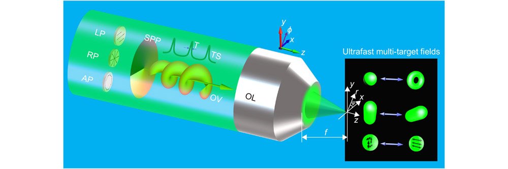
The ultrafast time-varying multi-target properties of optical fields in a high NA objective lens focusing geometry can be conceptually elucidated in Fig. 1. Femtosecond pulsed light beams with three sorts of polarizations (linearly, radially, and azimuthally) configured with general spatial phase and unconventional temporal phase are directly focused by a high NA aplanatic objective lens satisfying the sine condition r = f sinθ41. It should be noticed that we here utilized the intrinsic time phase factor of laser pulse with fleeting time to modulate incident light beam, and further to control and shape the tightly focused light fields. Mathematically, we first give the field distributions of an incoming linearly x- polarized, vortex-dressed Laguerre–Gaussian modes femtosecond pulsed light, which can be described as42, 43,
Figure 1.The conceptual schematic to yield ultrafast multi-target light fields in a single high NA objective focusing configuration. Right inset in black area represents the light fields with three sorts of patterned conversions as time elapses. Therein, the first row denotes the bright-dark alternative optical field especially for the radially polarized beam illumination; the second row shows periodic rotational light field actuated by arbitrary polarizations; the third row stands for reciprocal conversion between different polarized field components. LP: linear polarization; RP: radial polarization; AP: azimuthal polarization; SPP: spiral phase plate; TS: time sequence; OV: optical vortex; OL: objective lens.
where (r, , t) is the incoming time-dependent polar coordinate; σ0 and m stand for the beam waist and the topological charge of the incident beam; A(t) = exp[–(agt/T)2]exp(–iω0t) is the temporal pulse having a Gaussian shape envelope, in which ag = (2ln2)1/2, T denotes the pulse duration, as well as ω0 is its central angular frequency. According to the time-dependent vectorial diffraction theory16-17, 18, we can garner the focal light fields in the Fourier domain,
where the polarized unit vector matrix reads44, 45,
here, (r, φ, z) are the spatial cylindrical coordinates in the focal volume, i, j and k are the unit vectors with respect to the x, y, and z polarizations, respectively. k = ω/c is the wave vector related to the angular frequency ω of the carrier, and c = 3×10⁸ m/s is the light velocity in vacuum. α determined by sinα = NA is the maximal converging angle of the semi-aperture angle θ in the output pupil of the tightly focused optical system. f represents the focal length of the objective lens. Here the pupil apodization function of a single spectral component can be expressed as16, 17:
here E (r, t) refers to Eq. (1), where is eliminated during the calculation.
The local fields E (r, φ, z, t) mapped to the temporal domain can be described by the FFT of each polarized filed component. After a series of calculations, Eq. (2) can be rewritten as:
with
Jm(·) denotes the m-order Bessel function of the first kind and β = ωrsinθ/c.
In a similar fashion, the focal fields of radially polarized vortex-dressed Laguerre–Gaussian femtosecond pulsed light can also be deduced as,
where the polarized unit vector matrix45:
By leveraging the FFT, three orthogonal polarized field components of the radially polarized femtosecond pulsed light in the temporal domain can be calculated by the superposition of each spectral component as,
Based on Maxwell equations, the time-averaged Poynting vector components in the x, y, and z directions can be calculated via the three orthogonal electric field components and magnetic field components (see
Eqs. (S4)–(S6) in Supplemental information) determined by S = cRe(E × H*)/8π 46:
where Re(·) is the real part of the number, and the asterisk represents the complex conjugate of the variables.
Results and discussions
According to the Eqs. (1–10) and Eqs. (S1–S3) (Supplementary information), we examine in detail the dependence of focal field distributions and associated phase profiles of Laguerre–Gaussian vortex beams on various polarization states (linear, radial, azimuthal) and nontrivial temporal variations (0–350 fs, the distributions of t = 400 fs are similar to 0 fs, owing to the almost same contribution of the temporal phase to the focused light fields at such two moments), as shown in Figs. 2–4 and
Fig. S1 and
Fig. S6 in Supplementary information.
Figure 2.The focused field distributions of linearly polarized light with the first-order vortex at different temporal intervals. The total intensity distributions |Et|2 (a1–a8) as well as the transverse |Ex|2 (b1–b8), |Ey|2 (c1–c8) and the longitudinal |Ez|2 (d1–d8) field components in the x-y plane with the periodic time of t = 0 fs (a1–d1), 50 fs (a2–d2), 100 fs (a3–d3), 150 fs (a4–d4), 200 fs (a5–d5), 250 fs (a6–d6), 300 fs (a7–d7), and 350 fs (a8–d8). The color scale indicates the magnitude of the normalized intensity. The sizes for all of the images are 2λ×2λ. The other parameters are chosen as pulse width T = 5 fs, a laser beam with a center wavelength of 532 nm, central angular frequency ω0 = 3.543×10¹⁵ s–1, beam size σ0 = 2 cm, topological charge m = 1, and NA = 0.9.
For a linearly x-polarized beam illumination, we observe from Fig. 2 that both the x (Fig. 2(b1−b8)) and z (Fig. 2(d1−d8)) focal field components undoubtedly play a dominant role in any time stage for overall normalized optical field distributions (Fig. 2 (a1–a8)), while the y counterparts (Fig. 2(c1–c8)) could be neglected because of the tiny strength (10–3), which is in a good agreement with that reported in literature47. Incidentally, the magnitude of the x field component is always superior to that of the z counterpart in this case.
It is clearly seen that the total focal field and its field component perform versatile fertile patterns as time elapses. First, the total field distributions exhibit periodic behaviors ranging from initially compact button-like pattern, via ring-shaped structure with relatively weak sidelobe, and then to semilunar type possessing a two-fold rotation symmetry (Movie SL1). We further focus on the time-varying focusing characteristics of the remaining two component fields. On one hand, the spatial profile of transverse component (proportional to |Ex|2) starts to broaden slightly and subsequently rebounds to its original level within 0–350 fs. More importantly, we find that the rotation of the transverse components only occurs during 100–300 fs, whereas the rotational effect is hidden in the rest of temporal intervals (Fig. 2(b1–b8)). This situation can also be further verified in the corresponding phase galleries (
Fig. S1(a1–a8) and Movie SL2).
On the other hand, the longitudinal field component (proportional to |Ez|2) holds two dipole-shaped faint regions sandwiching a bright elliptic spot in the focal area at the static moment (t = 0 fs). As time goes by, two original sidelobes located at the x axis gradually strengthen and new outer-region sidelobes appear. Finally, the overall focal patterns return to the initial state as well (Fig. 2(d1–d8)). Interestingly enough, we observe the periodic rotation in the longitudinal field components within 0–350 fs duration, corresponding to a rotational rate 0.013 rad/fs regardless of the rotation direction (
Fig. S2(a–f)). The relevant details with respect to the general rotational process of the longitudinal field components, covering the dynamic process and the angle representations, are displayed in
Fig. S2 and Movie SL4. Similarly, the associated phase diagrams (
Fig. S1(c1–c8)) are also capable of illustrating these facts. Another aspect that needs to be noticed is the slight conversion between the transverse and longitudinal field components (see color bar in Fig. 2(b1–b8) and 2(d1–d8)). The appearances of these peculiar phenomena are in principle attributed to both the time-dependent Gouy phase shift and redistributed energy flux (
Fig. S3), which will be discussed systematically in the following section.
Figure 3.The focused field distributions of radially polarized light with the first-order vortex at different temporal intervals. The total intensity distributions |Et|2 (a1–a8) as well as the transverse |Ex|2 (b1–b8), |Ey|2 (c1–c8) and the longitudinal |Ez|2 (d1–d8) field components in the x−y plane with the periodic time of t = 0 fs (a1–d1), 50 fs (a2–d2), 100 fs (a3–d3), 150 fs (a4–d4), 200 fs (a5–d5), 250 fs (a6–d6), 300 fs (a7–d7), and 350 fs (a8–d8), respectively. Parameters are the same as those in Fig. 2.
Unlike the linearly polarized light illumination, the whole scenario changes drastically for the radially polarized light excitation. It is found from Fig. 3 that at t = 0 fs, the total field (Fig. 3(a1)) is completely dominated by three orthogonal field components (Fig. 3(b1–d1)). Apparently, the transverse field components (Fig. 3(b1) and 3(c1)) hold extended solid spots whereas the longitudinal one (Fig. 3(d1)) presents a symmetric donut pattern at the preliminary time. As time goes by, both the total field (Fig. 3(a1–a8)) and its each field component (Fig. 3(b1–b8), 3(c1–c8) and 3(d1–d8), respectively) manifest rich varying features within an observed temporal duration (~400 fs).
Firstly, as for the total fields (Fig. 3(a1–a8)) the original central bright spot starts to shrink gradually and then shifts into a marked hollow dark-core structure at about 113 fs (inset Fig. 5(c) or Movie SR1), as well as backtrack to the initial state at last. This bright-dark alternating variation is mainly due to the occurrence of constructive interference and destructive interference of the light wave with 0 or π phase difference at certain moments. In fact, the wavefront of the focal fields after passing through an aplanatic high NA objective lens may impose the slight frequency shift according to Eqs. (7)–(9), which inevitably introduces an extra additional π phase shift, as showcased in Fig. 4. Moreover, the reciprocal conversion between transverse and longitudinal fields also contributes to the bright-hollow alternating total field textures. Such ultrafast time-varying fields are highly attractive in applications, such as trapping two types of particles, and high-efficiency stimulated emission depletion microscope48-51.
Figure 4.A phase gallery of tightly focused radially polarized light with the first-order vortex at different temporal intervals. The phase distributions of the transverse |Ex|2 (a1–a8), |Ey|2 (b1–b8) and the longitudinal |Ez|2 (c1–c8) in the x−y plane with the time of t = 0 fs (a1–c1), 50 fs (a2–c2), 100 fs (a3–c3), 150 fs (a4–c4), 200 fs (a5–c5), 250 fs (a6–c6), 300 fs (a7–c7), and 350 fs (a8–c8), respectively. The white circles denote the rotational phases. The color scale indicates the magnitude of the phase. The sizes for all of the images are 2λ×2λ. Parameters are the same as those in Fig. 2.
Figure 5.Normalized Poynting vector fields along the propagating direction (the first row) and on the focal plane (the second to last rows) of the tightly focused radially polarized light with the first-order vortex at different temporal intervals when t = 0 fs, 100 fs, 200 fs, 300 fs, and 400 fs, respectively.The total Poynting vector fields St (the first row and the second row); radial Poynting vector fields Sr (the third row) and azimuthal Poynting vector fields Sφ (the fourth row) as well as longitudinal Poynting vector fields Sz (the last row). Parameters are the same as those in Fig. 2.
Secondly, it is clearly seen that two iso-intensity transversely polarized fields (Fig. 3(b1–b8) and 3(c1–c8)) possessing mutually perpendicular patterns can be accessible at any time. From a closer inspection of the demonstrated transverse field components, we discover their synchronized variation between single lobe and multilobes during the whole process. In particular, the corresponding field patterns appear to be rotated clockwise in the focal region (Movies SR2 and SR3), which is akin to the case in Fig. 2(d1–d8) with rotational ratio 0.013 rad/fs according to dφ/dt52. In principle, these prominent spinning behaviors hinge on the time-dependent Gouy phase shift. This anomalous phase shift, distinguished from the paraxial conditions, can be described by more universal form in a high NA geometry53. It takes the form on the optical axis: δi = arg[Ei]–kz' (i = x, y, z), with phase arg[Ei] for each field component and redefined axis location z' = zcosθ–Ωt/k. Ideally, the rotational optical fields are able to be changed by exploiting the completely novel degrees of freedom (DOFs): time intervals t (on the focal plane z = 0), allowing for the rotation of a prescribed orientation of particles. As is shown in Fig. 4, these distorted optical fields result from the change of positions where there exists 0/π phase reversal as time elapses. Considering another aspect of application, such well-defined optical field patterns are propitious to steer and control the ultrafast light-matter interaction54, 55.
Finally, as time elapses, the longitudinal field components (Fig. 3(d1–d8)) initially present a gradual decrease ranging from 56.3% to 23.6%, and then perform a progressive increase varying from 23.6% to 82.5% in a quasi-periodic manner (Movie SR4). On the contrary, the transverse field components show complementary variations during the corresponding temporal stages following the energy conservation law. This is mainly ascribed to a reciprocal conversion between the transversely and longitudinally polarized fields. The redistributed energy flux, supported by Eq. (10), is responsible for such a mutual conversion. To quantify the results, we plot the normalized Poynting vectors for the radially polarized illumination with t = 0 fs, 100 fs, 200 fs, 300 fs, 400 fs, respectively, as revealed in Fig. 5. It is found that both the strength (indicated by the colorbar) and polarization direction (indicated by the white arrows) of the total energy flux (St) alter together in different time durations (see the first and second rows in Fig. 5). This situation is confirmed to the interconversion between transverse energy flux (Sr and Sφ) and longitudinal counterpart (Sz) (see the last three rows in Fig. 5). It is well-known that the transverse energy flow in essence corresponds to the longitudinal electric field, and vice versa.
To further clarify the energy distribution, we firstly define a nontrivial tilt angle as ψ = arctan[(Sr2 + Sφ2)1/2/Sz2] to evaluate the conversions of the two orthogonal focal fields (detailed explanations and plot in
Fig. S10 in Supplementary information). For example, the transverse energy flow is prevailing when ψ < 45°; hence the corresponding longitudinal electric field plays a major role, and vice versa. In particular, if ψ = 45°, it indicates that the transverse field component is equal to the longitudinal one. More intuitively, we also clearly observe the conversion of the fields from the magnitudes of energy flux components (see the last three rows in Fig. 5). Taking the time intervals ranging from 100 fs to 300 fs as an exemplification, it is discovered that the transverse energy flux (see the third and fourth rows in Fig. 5) increases initially followed by a decrease (corresponding to the identical varying process of longitudinal electric fields in Fig. 3(d3–d7)), while the longitudinal energy flux (see the last row in Fig. 5) appear to be a reverse trend (corresponding to the same varying process of transverse electric fields in Fig. 3(b3–b7) and Fig. 3(c3–c7), respectively). As a comparison, we also plot the magnitudes and directions of Poynting vector of linearly polarized light beam in
Fig. S3 (Supplementary information). The magnetic fields on the focal plane and the corresponding total electric fields along the propagating directions are also shown in
Figs. S4 and
S5 (Supplementary information). Therefore, we could draw the following conclusion that the redistributed energy flux gives rise to the reciprocal conversions between the transverse and longitudinal field components.
To reveal more insights into the characteristic features of the demonstrated ultrafast multi-target focal fields, we study the focusing behaviors of the radially polarized beam illumination in detail at distinct time intervals: the total focal field distributions along the x and z axes (Fig. 6(a) and 6(b)), the rotational angles of transverse polarized fields (Fig. 6(c)) as well as the line scans of the normalized intensity of transverse/longitudinal polarized fields (Fig. 6(d)). In Fig. 6(a) and 6(b), we indeed observe that the focal fields perform a bright-to-dark process whether along the x or z axes as time elapses. Especially, the line scan (see yellow line) fully matches the hollow dark core pattern at 113 fs with a transverse full width half maximum (FWHM) of 0.484λ (inset in Fig. 6(a)). Secondly, we depict the rotational angles of x/y field components as a function of time (–400 fs–400 fs) in the polar coordinate (Fig. 6(c)), from which we find that t > 0 ( t < 0) is responsible for the clockwise (anticlockwise) rotation of the focal fields. In addition, it should be noted that the rotational angles enlarge rapidly near 100 fs, which corresponds to an angle of about π/2. Subsequently, the rotational angles vary relatively slowly during 100 fs–300 fs, as well as finally experience a dramatic reduction again from 300 fs to 400 fs. The variation in rotational angles of the focused light fields is in principle dictated by the derivative of the azimuthal angle with the time d φ/dt. As a result, the φ-dependent phase factor is dependent on both the spatial (kr) and temporal (ωt) phase terms. On the one hand, it is obvious that the strength of focused light fields varies rapidly when near 100 fs (see Fig. 6(d)). This is due to the fact that the related phase at this moment alters swiftly on the same spatial site, leading to the substantial enlarged rotational angles of the focused light fields. In sharp contrast, the strength of focused light fields varies relatively slowly between 100–300 fs due to the nearly constant phase (see Fig. 6(d)). Therefore, the rotational angles of the focused light fields are almost unchanged. Notably, the rotational angles in t < 0 take on the same variation tendency. In Fig. 6(d), we observe that both the transverse (x and y field components overlap together) and z field components change smoothly between 105–150 fs. Thus, the polarization conversions hardly exist under such a circumstance. However, at other time intervals, they exhibit a rapid complementary variation, which implies that reciprocal conversion arises between transversely and longitudinally polarized optical fields. In a similar fashion, we study the focal field distributions and associated phase patterns of the azimuthally polarized light illumination (
Fig. S6), from which only the rotational field component is observed yet other focused features are absent. Overall, in comparison with the linearly and azimuthally polarized lights illumination, we could declare that the radially polarized light is a suitable candidate to control ultrafast multi-target light fields in a single optical setup (more simulation results for radially polarized light fields with topological charges of 2 and 3 are provided in
Figs. S15 and
S16, respectively).
Figure 6.Ultrafast multi-target control of the focal light fields for the radially polarized light illumination. (a) and (b) the intensity distributions of the total focal field along the x and the z axes at different temporal intervals with t = 0 fs, 100 fs, 113 fs, 150 fs. (c) the rotational angles of the x/y field components (overlapped) as time elapses. (d) the normalized intensity curves of transverse (overlapped black solid line and red dotted line) and longitudinal field components (blue solid line) as a function of time during 0–400 fs.
As analyzed above, twofold crucial issues need to be clarified. Firstly, one can see that the laser parameter used in the theoretical analysis is a femtosecond laser with pulse width of 5 fs and central wavelength of 532 nm, while the temporal interval of 100 fs is much longer than the pulse width of the laser. In this respect, we should note that in our case the continuous pulse packets arrive at the fixed focal plane one by one, fleeting through the focal plane and propagating to the far-field zone. Therefore, a train of 5 fs pulses could show the temporal variation in 100 fs and even more. Secondly, ultrashort laser pulse can produce certain group velocity dispersion (GVD) and group delay dispersion (GDD) when it transmits cascaded optical devices or dispersive materials, which broadens the pulse width and thus affects the ultrafast multi-target control of light fields. However, it should be noted here that the results are all demonstrated in free space. As a result, the influence of GVD and GDD on the ultrafast multi-target control of light fields can be reasonably ignored if considering achromatic optical devices in our theoretical considerations.
To facilitate the realization of such novel beam manipulation, we propose the experimental configuration in
Fig. S7, and generate various cylindrical vector beams as well as detect their tightly focused light fields at a static time (t = 0 fs) as shown in
Figs. S8 and
S9. The experiment can be composed of three critical detachable sections: modulation, shaping, and observation of time-dependent focal fields, respectively. First, we start from a femtosecond laser delivering linearly polarized laser pulse utilized as the excitation source, which first passes through a telescope configuration made of two lenses (L1 and L2) and an iris to collimate the beam. The light is subsequently impinged on a half-plate (λ/2) to control the output power. Second, the stable output laser pulse is divided into two paths after passing through a beam splitter, where one path travels in a straight line and the other hits on a system called optical delay lines, formed by two low group delayed dispersion (GDD) reflected mirrors and a knife-edge prism mirror mounted on a computer-controlled translation stage, for jointly implementing modulation of ultrafast temporal intervals (delayed single step ~3 fs and total run 10 micron). Subsequently, these two path lights are combined by the other beam splitter. As for the optical field shaping, inspired by ‘zero dispersion pulse compressor’56, the divided femtosecond pulse light path is sent to femtosecond vector vortex pulse shaper consisting of a diffraction grating G (1200 lines mm−1) and a spatial light modulator (SLM) at the input and output of a 2f system (cylindrical lens L3) along with vortex retarder (VR), respectively. At this stage, a pair of diffractive gratings and cylindrical lens execute space-time FFT and its inverse FFT. Also, SLM is utilized for controlling amplitude and phase structures, and VR (for example from LBTEK) can yield required vector vortex optical fields. Last but not least, the synthetic time-dependent vector vortex pulse light is tightly focused with a high NA (NA = 0.9) objective lens onto a subwavelength nanoparticle sitting on glass substrate moved by 3D nano-positioning system57, 58. The transmitted light is collected via another high NA (NA =1.3) objective lens and imaged by a commercial charge coupled device (CCD). Thus, the resulting ultrafast multi-target light field can be reconfigured based on this so-called nano-probe scanning system59. Special caution needs to be paid on the unavoidable dispersion of the optical elements, the limited spectral bandwidth of the gratings, and confined pupil size of the SLM, which might impact the experimental measurement.
Conclusions
In summary, we have theoretically demonstrated ultrafast and multi-target control of light fields in free space for the first time by tightly focusing the vortex-dressed Laguerre–Gaussian femtosecond pulse light, based on the time-dependent vectorial diffraction theory and the FFT. We found that the bright-dark alternating fields arise within a temporal duration (~400 fs). In particular, dark-core structure induced by radially polarized light emerges at 113 fs, which is ascribed to the constructive/destructive interference stemming from new frequency shift by tight focusing of optical field and the FFT. As a potential application perspective, this peculiar time-varying focal field will be propitious to trap two types of particles within ultrashort time regimes. Furthermore, because of the time-dependent Gouy phase shift, the focal fields rotate clockwise/anticlockwise and the corresponding average rotation rate reaches up to 0.013 rad/fs. As such, taking advantage of such ultrafast rotated focal fields to instantly revolve the prescribed microscopic particles is promising. In parallel, it is unraveled that in our setup the reciprocal conversion between transversely and longitudinally polarized fields indeed exists as time elapses. This is in principle due to the fact that internal energy flux redistributes throughout the focal plane. One perhaps sort on-demand anisotropic particles possessing specific polarization reactions by resorting to the polarization-transformed fields. In addition, we give a prototypical experimental paradigm regarding the ultrafast control of optical fields and discuss its possible limitation. The findings presented here not only have significant implications for the fundamental understanding of how space-time coupling wave packets propagate in free space/medium on ultrafast nano-optics realm, but also provide huge opportunities for profound new applications in light-matter interactions, multifunctional integrated optical chip, ultrafast optical device and ultrafast optical tweezer. Further generalization of burgeoning working is required to establish the inseparable space-time effect of higher-order vector beams and will hopefully inspire more interesting researches in this field.
References
[7] Osellame R, Vazquez RM, Dongre C, Dekker R, Hoekstra HJWM et al. Femtosecond laser fabrication for the integration of optical sensors in microfluidic lab-on-chip devices. In Proceedings of the 16th International Conference on Ultrafast Phenomena XVI 973–975 (Springer, 2009); https://doi.org/10.1007/978-3-540-95946-5_315.
Yanxiang Zhang, Xiaofei Liu, Han Lin, Dan Wang, Ensi Cao, Shaoding Liu, Zhongquan Nie, Baohua Jia. Ultrafast multi-target control of tightly focused light fields[J]. Opto-Electronic Advances, 2022, 5(3): 210026