
Songbin Liu, Long Yan, Jinshu Huang, Bo Zhou. Nanostructure Design, Multi-Color Manipulation and Application of Orthogonal Upconversion Materials[J]. Laser & Optoelectronics Progress, 2021, 58(15): 1516005
- Laser & Optoelectronics Progress
- Vol. 58, Issue 15, 1516005 (2021)
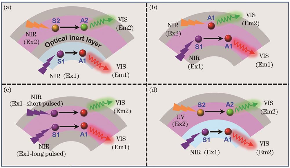
Fig. 1. Schematic of core-shell structure for orthogonal luminescence. (a) Double-emission layer design for orthogonal upconversion; (b) single-emission layer design for steady-state orthogonal upconversion; (c) single-emission layer design for non-steady-state orthogonal upconversion; (d) double-emission layer design for upconversion/downshifting dual-modal luminescence
![Double-emission layer design for dual-color orthogonal upconversion. (a) Schematic of NaGdF4∶Yb/Tm@NaGdF4@NaYbF4∶Nd@Na(Yb,Gd)F4∶Ho@NaGdF4 core-shell structure for blue-green dual-color orthogonal upconversion and its upconversion emission spectra and photograph under 980/808 nm excitation[27]; (b) upconversion emission spectra and photograph of NaGdF4∶Yb/Er@NaYF4∶Yb@NaGdF4∶Yb/Nd@ NaYF4@NaYF4∶Yb/Tm@NaYF4 core-shell sample[24]; (c) upconversion decay curves of Er3+ and Tb3+ after NaGdF4∶Yb/Tm coating with additional NaGdF4∶Tb[26]; (d) schematic of NaErF4@NaYF4@NaYbF4∶Tm@NaYF4 core-shell structure for blue-red dual-color orthogonal upconversion and its upconversion emission spectra and photograph under 980/800 nm excitation[36]; (e) schematic of core-shell structure by combining various dopants for red-green/red-blue dual-color orthogonal upconversion[29]; (f) upconversion emission photographs of NaErF4-based multilayer orthogonal core-shell samples under 808/980/1550 nm excitation[29]](/richHtml/lop/2021/58/15/1516005/img_2.jpg)
Fig. 2. Double-emission layer design for dual-color orthogonal upconversion. (a) Schematic of NaGdF4∶Yb/Tm@NaGdF4@NaYbF4∶Nd@Na(Yb,Gd)F4∶Ho@NaGdF4 core-shell structure for blue-green dual-color orthogonal upconversion and its upconversion emission spectra and photograph under 980/808 nm excitation[27]; (b) upconversion emission spectra and photograph of NaGdF4∶Yb/Er@NaYF4∶Yb@NaGdF4∶Yb/Nd@ NaYF4@NaYF4∶Yb/Tm@NaYF4 core-shell sample[24]; (c) upconversion decay curves of Er3+ and Tb3+ after NaGdF4∶Yb/Tm coating with additional NaGdF4∶Tb[26]; (d) schematic of NaErF4@NaYF4@NaYbF4∶Tm@NaYF4 core-shell structure for blue-red dual-color orthogonal upconversion and its upconversion emission spectra and photograph under 980/800 nm excitation[36]; (e) schematic of core-shell structure by combining various dopants for red-green/red-blue dual-color orthogonal upconversion[29]; (f) upconversion emission photographs of NaErF4-based multilayer orthogonal core-shell samples under 808/980/1550 nm excitation[29]
Fig. 3. Double-emission layer design for RGB orthogonal upconversion. (a) TEM image, upconversion emission spectra and photographs of NaYF4∶Nd/Yb@NaYF4∶Yb/Tm@NaYF4@NaYF4∶Yb/Ho/Ce@NaYF4 core-shell the above sample under various 808/980 nm excitation conditions[28]; (b) schematic of upconversion energy transfer mechanisms of the above sample under 980 nm pulsed laser excitation[28]; (c) multicolor upconversion emission photographs of the above sample under various 808/980 nm excitation conditions[28]; (d) schematic of energy transfer processes for realizing full-color orthogonal upconversion in NaYF4∶Nd/Yb@NaYF4∶Yb/Tm@NaYF4@NaYbF4∶Ho@NaYF4 core-shell structure[29]; (e) upconversion emission intensity ratio of red and green (R/G) and photographs under 808/980 nm excitations with various pump power densities [29]
Fig. 4. Single-emission layer design for orthogonal upconversion. (a) TEM morphology image of NaYbF4∶Er/Tm@NaYF4∶Yb core-shell sample and schematic of proposed energy migration processes[42]; (b) upconversion emission spectra and photographs of the above sample under 808/980 nm excitation[42]; (c) upconversion emission spectra and photographs of NaErF4@NaYbF4 core-shell sample under 980/1530 nm excitation[31]; (d) schematic of structure design to realize red-green orthogonal upconversion in NaErF4∶Yb/Tm@NaYbF4 core-shell sample[39]; (e) upconversion emission spectra of the sample in Fig. 4(d) under 980 nm excitation at different pulse widths[39]; (f) CIE chromatic coordinates and photographs of the sample in Fig. 4(d) under 980 nm excitation at different pulse widths[39]
Fig. 5. Double-emission layer design for upconversion/downshifting dual-modal luminescence. (a) Schematic of core-shell structure design for dual-modal luminescence[46]; (b) upconversion emission spectra of NaGdF4∶20%Yb/2%Ho/12%Ce@NaYF4∶Eu core-shell sample under 980 nm excitation[46]; (c) down-shifting excitation and emission spectra as well as photographs of NaGdF4∶Yb/Ho/Ce@NaYF4∶A (A=Eu, Tb, Sm, Dy, Nd) core-shell sample[46]; (d) schematic of dual-modal luminescence in LiYbF4∶Y@LiGdF4∶Yb/Tm@LiYF4∶A@LiGdF4∶Ce core-shell structure under 980/254 nm excitation[40]; (e) tri-channel emission spectra and corresponding emission color photographs under single-excitation of 980, 254 nm, and dual-excitation of them, respectively[40]
Fig. 6. Typical applications of orthogonal upconversion. (a) Three-dimensional volumetric full-color display[28]; (b) information security[31]; (c) anti-counterfeiting[26]; (d) DNA nano-device for programmed tumor cell recognition and treatment[37]
|
Table 1. Summary of orthogonal luminescence of multicolor output and modulation types

Set citation alerts for the article
Please enter your email address
© Copyright 2018-2021 | Chinese Laser Press. All Rights Reserved 沪ICP备15018463号-20