
Xinjun Wang, Yingliang Yan. Microstructure and Properties of Laser Cladding 316L Stainless Steel Coating Assisted by Magnetic Field[J]. Laser & Optoelectronics Progress, 2020, 57(23): 231401
- Laser & Optoelectronics Progress
- Vol. 57, Issue 23, 231401 (2020)
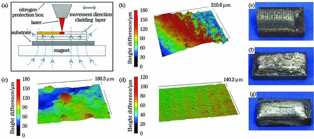
Fig. 1. Schematic of forming principle and comparison of surface morphology. (a) Schematic of forming principle; (b)--(d) confocal surface morphologies corresponding to B=0, 200, 400 mT, respectively; (e)--(g) macroscopic surface morphologies corresponding to B=0, 200, 400 mT, respectively
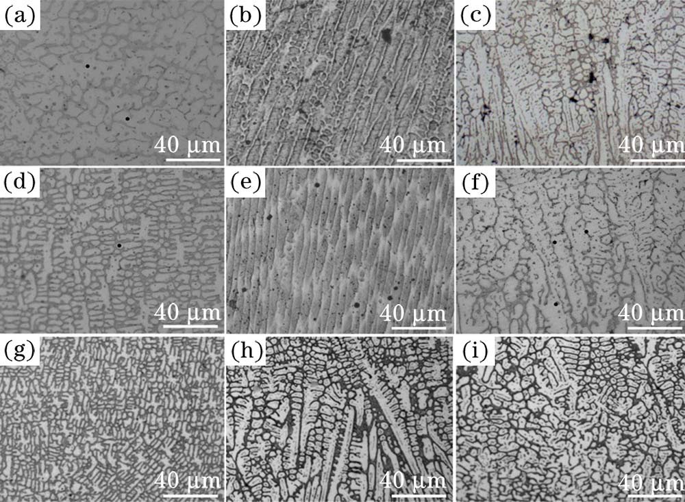
Fig. 2. Comparison of microstructure under three magnetic fields. (a)--(c) Top, middle, and bottom of cladding layer when B=0 mT; (d)--(f) top, middle, and bottom of cladding layer when B=200 mT; (g)--(i) top, middle, and bottom of cladding layer when B=400 mT
Fig. 3. XRD and microhardness. (a) XRD pattern of cladding layer; (b) microhardness distribution curve
Fig. 4. Friction and wear experiment. (a) Friction coefficient; (b) mass loss; (c)--(e) wear morphology under B=0, 200, 400 mT, respectively
Fig. 5. Potentiodynamic polarization curve
|
Table 1. Performance parameters of 316L stainless steel substrate
|
Table 2. Electrochemical corrosion parameters of three cladding layers

Set citation alerts for the article
Please enter your email address
© Copyright 2018-2021 | Chinese Laser Press. All Rights Reserved 沪ICP备15018463号-20