
Shujun Xing, Liangcai Cao, Xinzhu Sang, Xunbo Yu, Guofan Jin. Overview of Virtual Stereo Content Generation Technology for Super Multi-View Light Field[J]. Chinese Journal of Lasers, 2021, 48(15): 1509001
- Chinese Journal of Lasers
- Vol. 48, Issue 15, 1509001 (2021)
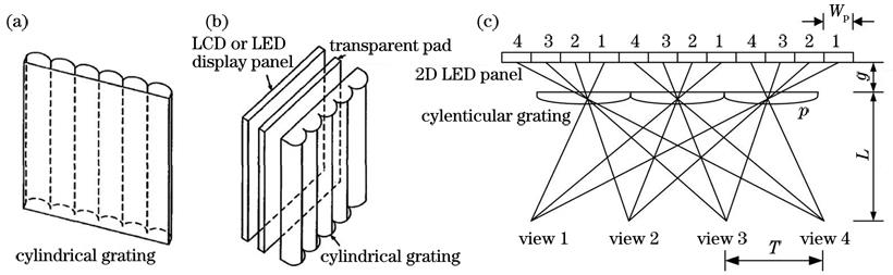
Fig. 1. Structure and principle of cylindrical grating stereoscopic display. (a) Cylindrical grating; (b) cylindrical grating stereoscopic display; (c) principle of light splitting for cylindrical grating stereoscopic display
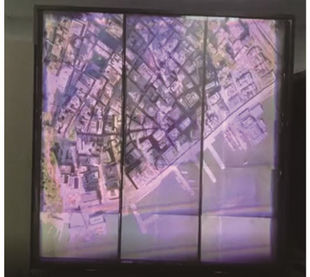
Fig. 2. Cluster light-field stereoscopic display consists of 15 8K LCD panels, 15 laser sources, and super large-format cylindrical grating
Fig. 3. Naked eye stereoscopic displays based on eye tracking. (a) Dimenco 8K eye-tracking naked eye stereoscopic display[7]; (b) Sony eye-tracking naked eye stereoscopic display[8]
Fig. 4. Schematic diagram of acquisition and reproduction processes of integrated imaging. (a) Acquisition process; (b) reproduction process
Fig. 5. Light field display of integral imaging, and full-parallax light field electronic sand table. (a) Light-field display of integral imaging; (b) full-parallax light field electronic sand table
Fig. 6. HoloVizio display system and 360° projection light-field system. (a) HoloVizio display system; (b) 360° projection light-field system
Fig. 7. Parameter comparison of typical light-field displays
Fig. 8. Suspension of spherical concave mirror[18]
Fig. 9. Suspension of spherical concave mirror
Fig. 10. Typical structural diagram of suspended display based on retroreflection[23] ( cylindrical grating stereoscopic display device can be replaced by general display, and suspended object is two-dimensional plane). (a) Levitating display device based on concave mirror; (b) suspension display device based on reverse reflection film
Fig. 11. Suspended light field stereoscopic display with large size and high definition. (a) Left viewpoint image; (b) middle viewpoint image; (c) right viewpoint image
Fig. 12. Basic principle of glass panel with negative refraction. (a) Structural chart; (b) light-path diagram
Fig. 13. Schematic diagram of four-dimensional light field acquisition[3]
Fig. 14. Transformation from camera coordinate system to world coordinate system
Fig. 15. Linear projection transformation, and normalized device coordinate system. (a) Linear projection transformation; (b) normalized device coordinate system
Fig. 16. Setting methods of view frustum for multi-view stereo camera. (a) Parallel type; (b) cluster type; (c) sheared type
Fig. 17. Flow chart of view-by-view rendering based on serial rasterization
Fig. 18. Copy method of primitives based on geometric shaders[31]
Fig. 19. GPU instancing technology in Unity 3D, solving computational efficiency problem of generous repetitive objects
Fig. 20. Principles of perspective projections. (a) Common perspective projection; (b) reverse perspective projection
Fig. 21. Applications of inverse perspective drawing. (a) Religious painting; (b) special construction
Fig. 22. Shadow elimination of general linear perspective projection, and shadow elimination of inverse perspective projection. (a) Shadow elimination of general linear perspective projection; (b) shadow elimination of inverse perspective projection
Fig. 23. Integrated imaging algorithm based on ray tracing[39]
Fig. 24. Flow chart of bilateral DIBR algorithm
Fig. 25. Multi-view images and corresponding EPI image[55]
Fig. 26. Light field acquisition of virtual points with staggered arrangement and corresponding EPI image
Fig. 27. Parameters of grating stereoscopic display
Fig. 28. Generation of elemental images in light field
Fig. 29. Correction of projectors[61]
| ||||||||||||||||||||||||||||||||||||||||||||||||||||||||||||||||||||||||||||||||||||||||||||||||||||||||||||||||||||||||||||||||||||||||||||||||||||||||||||||||||||||||||||||||||||||||||||||||||||||||||||||||||||||||||||||||||||||||||||||||||||||||||||||||||
Table 1. Features of super multi-viewpoint light-field rendering algorithms and encoding, correction, and synchronization algorithms running on a variety of light-field display devices


Set citation alerts for the article
Please enter your email address

© Copyright 2018-2021 | Chinese Laser Press. All Rights Reserved 沪ICP备15018463号-20