• Photonics Research
  • Vol. 2, Issue 4, B11 (2014)
Ning Zhang1、2, Xinlun Cai2, and and Siyuan Yu1、2、*
Author Affiliations
  • 1Department of Electrical and Electronic Engineering, University of Bristol, Bristol BS8 1UB, UK
  • 2State Key Laboratory of Optoelectronic Materials and Technology, School of Physical Science and Engineering Technologies, Sun Yat-sen University, Guangzhou 510 275, China
  • show less
    DOI: 10.1364/PRJ.2.000B11 Cite this Article Set citation alerts
    Ning Zhang, Xinlun Cai, and Siyuan Yu. Optical generation of tunable and narrow linewidth radio frequency signal based on mutual locking between integrated semiconductor lasers[J]. Photonics Research, 2014, 2(4): B11 Copy Citation Text show less
    Schematic diagram of RF signal generation circuit based on mutual locking among two DFB lasers and one SRL.
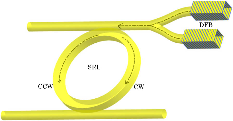
    Fig. 1. Schematic diagram of RF signal generation circuit based on mutual locking among two DFB lasers and one SRL.
    Spectra of (a) dual DFB injection-locked SRL modes in the CCW and CW directions, and (b) generated RF signal by beating the two lasing modes in the CCW direction. Pdfb1,2=0.23 dBm, Psrl−fr=−20.3 dBm, and Δω=0.
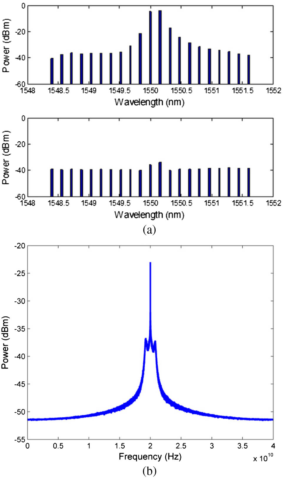
    Fig. 2. Spectra of (a) dual DFB injection-locked SRL modes in the CCW and CW directions, and (b) generated RF signal by beating the two lasing modes in the CCW direction. Pdfb1,2=0.23dBm, Psrlfr=20.3dBm, and Δω=0.
    FN curves of DFB lasers, SRL, and the generated RF signals.
    Fig. 3. FN curves of DFB lasers, SRL, and the generated RF signals.
    Linewidth of the generated RF signal as a function of tuning frequency.
    Fig. 4. Linewidth of the generated RF signal as a function of tuning frequency.
    Influence of backscattering coefficient and feedback phase change on the linewidth of the generated RF signal. (a) General evolution, with linewidth expressed in log, (b) results of two special k values. Pdfb1,2=0.23 dBm, Psrl=−20.3 dBm, and Δω=0.
    Fig. 5. Influence of backscattering coefficient and feedback phase change on the linewidth of the generated RF signal. (a) General evolution, with linewidth expressed in log, (b) results of two special k values. Pdfb1,2=0.23dBm, Psrl=20.3dBm, and Δω=0.
    Linewidth of the generated RF signal (in log) as a function of (a) power ratio (Pdfb/Psrl), where Pdfb=Pdfb1=Pdfb2 and Δω=0, and (b) power ratio (Pdfb2/Pdfb1), where Pdfb1=0.23 dBm and Δω=0.
    Fig. 6. Linewidth of the generated RF signal (in log) as a function of (a) power ratio (Pdfb/Psrl), where Pdfb=Pdfb1=Pdfb2 and Δω=0, and (b) power ratio (Pdfb2/Pdfb1), where Pdfb1=0.23dBm and Δω=0.
    Linewidth of the generated RF signal (in log) as a function of the injection frequency detuning of the two DFB lasers.
    Fig. 7. Linewidth of the generated RF signal (in log) as a function of the injection frequency detuning of the two DFB lasers.
    ParameterDescriptionValueUnit
    VVolume of the active region150μm3
    LdfbLength of DFB laser300μm
    ndfbRefractive index of the active region3.525
    αdfbLinewidth enhancement factor5
    Gth0Threshold gain level2.44×1011s1
    NgElectron number at transparency1.328×108
    RfPower reflectivity of the front facet0.2
    RbPower reflectivity of the back facet0.9
    kdfbCoupling ratio into DFB laser cavity0.3
    Table 1. Values of the DFB Parameters Used for Numerical Simulation
    ParameterDescriptionValueUnit
    LsrlSRL cavity length4106μm3
    N0Transparency carrier density2.2×1024m3
    αsrlLinewidth enhancement factor1. 57
    aGain-slope coefficient6.35×1020m2
    nsrlGroup index3.7
    kcConservative coupling0.0044s1
    kdDissipative coupling0.000327s1
    kcpCoupling ratio into SRL cavity0.3
    τpPhoton lifetime in SRL10ps
    λ0Central lasing wavelength1550nm
    Table 2. Values of the SRL Parameters Used for Numerical Simulation
    Ning Zhang, Xinlun Cai, and Siyuan Yu. Optical generation of tunable and narrow linewidth radio frequency signal based on mutual locking between integrated semiconductor lasers[J]. Photonics Research, 2014, 2(4): B11
    Download Citation