1Department of Electrical and Electronic Engineering, University of Bristol, Bristol BS8 1UB, UK
2State Key Laboratory of Optoelectronic Materials and Technology, School of Physical Science and Engineering Technologies, Sun Yat-sen University, Guangzhou 510 275, China
Ning Zhang, Xinlun Cai, and Siyuan Yu. Optical generation of tunable and narrow linewidth radio frequency signal based on mutual locking between integrated semiconductor lasers[J]. Photonics Research, 2014, 2(4): B11
Copy Citation Text
An integrated on-chip optical device consisting of two distributed feedback (DFB) lasers and one multimode semiconductor ring laser (SRL) has been numerically investigated. In this optical circuit, the two DFB lasers are injected into the SRL, and with the presence of the four-wave mixing effect and optical feedback, the three semiconductor lasers achieve mutual-locking state. The beating between the output optical spectral lines can generate readily tunable radio frequency signals with high spectral purity.
The ever-higher end-user data rate drives the strong requirement of flexible, energy-efficient, and broadband access services anywhere at any time [1]. Among different solutions for this topic, radio-over-fiber (RoF) technology, which combines the advantages of wireless access and fiber optics, is a promising one. To optimize the utilization of RoF technology, generation of radio frequency (RF) sources with high spectral purity (linewidth ) and wide tunability is a fundamental problem [2].
In recent years, optical generation of RF source carriers has received increasing interest since compared with electrical methods, optical methods provide immunity to electromagnetic interference (EI) and high flexibility, and are capable of generating multiples of a reference oscillator frequency. Also, integrated optical technology offers other advantages, such as compactness, low power consumption, and low cost [3]. Numerous optical methods have been reported for the generation of tunable and high-purity RF carriers, including those based on optical frequency combs, modulation side-mode injection locking, optical feedback (OFB) loops, and optical photomixing, as well as combinations of the above approaches. Generally speaking, frequency comb generation typically requires complex and bulky systems [4]. Similarly, side-band injection-locking methods need extra isolators that are hard to be integrated onto a single chip [5]. Methods employing OFB loops can achieve high spectral purity RF sources but suffer from limited tunable range [6]. On the other hand, optical photomixing, which is based on the coherent superposition of two single-mode lasers onto an ultrafast oscillator, provides a simple mechanism to generate RF signals with an extremely flexible tuning range, since semiconductor lasers can be tuned easily [7]. Meanwhile, to improve the spectral purity of the RF signals, the coherence between the two optical sources must be highly enhanced [8]. In this way, more complex systems have been developed based on the traditional optical photomixing method, including the use of RF reference sources and OFB loops [9].
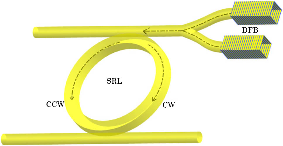
A novel optical scheme based on the photomixing technique for the generation of RF signals with high purity and wide locking bandwidth is proposed and discussed here. The illustration diagram of this scheme is given in Fig. 1. This scheme includes two distributed feedback (DFB) lasers and one multimode semiconductor ring laser (SRL). The DFB laser is a widely used high spectral performance laser. For SRL, the special bidirectional operation regimes [10] and its highly efficient nonlinear effect [11] allow us to utilize it as a promising resonator choice for photomixing. In this scheme, the light beams emitted from the two DFB lasers, as external optical injection sources, are first injected into two different longitudinal modes of the SRL. These two injection-locked longitudinal modes travel in the same direction, e.g., counterclockwise (CCW), as shown in Fig. 1. The two injected modes are phase locked via the four-wave mixing (FWM) effect within the ring. Meanwhile, light travels in the opposite direction in the ring, e.g., clockwise (CW), as shown in Fig. 1, as external OFB copies the information of the injection-locked modes back to the two DFB lasers. Therefore, phase correlation is achieved via both the FWM effect in the SRL and the feedback loop between SRL and DFB lasers and the three semiconductor lasers achieve mutual locking. The beating of the two injection-locked modes of SRL, or of the two DFB lasers, can generate RF signals with narrow linewidth. A wide frequency tuning range of the generated RF signals can be easily achieved by tuning the two DFB lasers targeting at different longitudinal modes in SRL. Moreover, since there is no isolator used in this scheme, the whole photonic circuits can be readily integrated onto a single photonic chip.
Sign up for Photonics Research TOC. Get the latest issue of Photonics Research delivered right to you!Sign up now
Figure 1.Schematic diagram of RF signal generation circuit based on mutual locking among two DFB lasers and one SRL.
In this paper, we carry out a numerical investigation of this scheme. A numerical model is presented in Section 2. The simulation results are presented in Section 3. In Section 4, conclusions and future work guidelines are given.
2. NUMERICAL MODEL
The numerical analyses of this photonic circuit include three parts: the semiconductor lasers, external optical injection locking (OIL), and the OFB loop. Injection is added into the multimode SRL model. The frequency domain SRL model also includes the linear and nonlinear mode interactions, which are the driving forces of SRL characteristics [12]. As outlined above, we believe the nonlinear process causes strong phase correlations between the two injection-locked modes and also between the two DFB lasers. On the other hand, the feedback is added into the DFB models [13]. Since the DFB lasers are the injection sources of SRL and SRL is the feedback source of DFB, the mutual-locking process between the three lasers is then initiated. The whole numerical model is established on the hypothesis that the optical fields have slowly varying complex amplitude in SRL and DFB laser. The rate equation systems and relative equations are written and analyzed as below.
A. Rate Equations
In the equations above, Eqs. (1) and (2) represent the time evolution of the carrier density and electric field in the DFB lasers. The feedback is written in the form of the feedback gain . The multimode SRL model is developed based on our previous work [14]. Equations (3) and (4) describe the time variation of the electric field of each single mode and the total carrier density. The nonlinear coupling process between different modes in SRL is expressed as . The linear coupling between two propagation directions in SRL is expressed as , where is the electric field of the modes in the opposite propagation direction and is the backscattering coefficient. Backscattering is a linear coupling process, including localized and distributed intra-/extra-cavity backscattering. Intra-cavity backscattering is mainly caused by distributed backscattering related to waveguide roughness, and localized backscattering related to discontinuities in the ring cavity. Extra-cavity backscattering is mainly caused by reflections from the facets or output waveguides [15]. Backscattering coefficient has the dimension of and contains two parts: the real part (dissipative coupling) and the imaginary part (conservative coupling). is an important coefficient in SRL since its value determines the strength and the phase shift in the linear coupling between the two counterpropagating modes. Here in our scheme, its value directly affects the mutual-locking condition between different lasers, and hence the linewidth of the generated RF signal. The external injection sources to the SRL are written as , which only exits for the two injection-locked modes. The spontaneous noise in each laser is considered via adding a noise source term at the end of each rate equation. The intrinsic linewidth of a laser arises from quantum fluctuations that are determined by the spontaneous emission process [16].
B. Optical Injection Locking
OIL is an important optical technique, and it has been proved that under OIL condition, the power and the phase fluctuation in the slave laser are both locked by the master laser [17]. If the master laser has high lasing power and low quantum noise, like the DFB lasers in our scheme, the lasing characteristics of the slave laser will be significantly improved via OIL [18]. To describe this physical process numerically, we add an extra injection item in the time evolution equation for the two injection-locked modes in SRL. The expression of is In the expressions above, is the selection rule and is nonzero only when the considered mode is under injection locking. The nonzero value of has a reciprocal relation with the sum of the light traveling time in the ring cavity and in the feedback loop. is the coupling ratio of the signal power in the waveguide coupled into the ring laser. is the frequency detuning of the DFB laser away from the frequency of the targeted longitudinal mode in SRL. The injection ratio can be defined as the power of compared with that of in the lasing direction without injection. The value of injection frequency detuning and the injection ratio will influence the locking efficiency between lasers.
C. Optical Feedback
OFB has been proved as an effective technology to improve the performance of OIL systems [19,20]. In an OFB loop, the strength of the feedback signals and the phase change caused in the loop are both important variables. The numerical descriptions of the feedback terms added to two DFB lasers are In the above equations, is the feedback coupling ratio, which is determined by the front facet reflection ratio of DFB and the coupling ratio to the laser cavity. is the extra phase change caused by the feedback loop, which can be calculated according to the distances between the DFB lasers and the SRL. From the expressions above we could tell that the modes in the noninjected direction of SRL produce the delayed feedback signals, with both amplitude and phase information. Meanwhile, the phase change also affects the extra phase information of the feedback signals. In the presence of the backscattering coefficient , the feedback signals “copy” the information from the two corresponding modes in the opposite propagation direction. These two “copied” modes, again, are injection-locked by DFB lasers that carry correlated phase information induced by the feedback signals. This feedback loop will then reach the steady state, leading the whole system into the mutual-locking condition. Therefore, to optimize the locking efficiency of this system, the values of and need to be well adjusted. Detailed discussion of these two coefficients is given in Section 3.
D. Nonlinear Process in SRL
The nonlinear effects expressing the coupling on the th mode in the presence of material oscillations caused by the beating of the th mode and th mode scattering th mode can be described as [21]: Here the total third-order polarization on the th mode is given by summing all the individual oscillations. The expression of in the SRL cavity has been developed before based on density matrix theory [21,22]. The value of is determined by the physical characteristics of the semiconductor material, the carrier density within the cavity, and the frequency difference between the modes involved. Hence the nonlinear efficiency is relatively high near the center region of the gain profile. is the selection rule and is equal to 1 when the four modes satisfy the phase matching condition; otherwise equals 0. Considering the fact that the ring cavity supports traveling longitudinal modes, the nonlinear mode coupling in SRL via third-order nonlinearity has been proved to be more efficient, especially FWM, which is 4 times more efficient compared with an equivalent Fabry–Perot (F-P) laser [11]. FWM is a phase sensitive process that could lead to power exchange among different modes. Via the energy coupling process, FWM also induces a phase-locking phenomenon due to its coherent nature. The phase correlation is enhanced under the dual-injection-locking condition since FWM efficiency between the adjacent injection-locked modes is elevated. In this way, the FWM process within the SRL cavity provides strong phase correlations between the two injection-locked modes and then helps to achieve mutual locking among the three lasers together with the presence of a feedback loop.
E. Frequency Noise Analysis and Linewidth
The noise content of the phase fluctuations is determined in terms of frequency noise (FN) [23], which indicates the frequency shift from the central lasing frequency of the laser. To simulate the phase fluctuations, we use the Langevin and Gaussian noise sources. The electric field noise source term is a complex Langevin noise source, with each of the real and imaginary parts having a Gaussian probability distribution with a zero mean. The carrier number noise source term is a real Gaussian noise source. The expressions of these two types of sources are Here is the autocorrelation of each variant and is a Gaussian random variable, and the three are independent of each other. When the noise sources are considered, the FN response can be calculated using the expressions below: The laser linewidth, which is the full width at half-maximum (FWHM) of the spectrum, can be calculated from the low frequency value of the FN under the approximation that the main contribution to the linewidth comes from white noise and gives a Lorentzian spectral line shape as described in [24]: Though from the computational standpoint, the calculation of FN is hard to extend to , the low fluctuation of the FN curve at the low frequency side allows us to estimate the linewidth value at a frequency far lower than the resonant frequency of the laser.
3. SIMULATION RESULTS AND DISCUSSION
The numerical model based on rate equations established in Section 2 is solved by means of a fourth-order Runge–Kutta method. The important parameters for DFB lasers and SRL are listed in Tables 1 and 2, respectively. The parameters are fitted from former experimental measurement [22]. The time step of the integration is set as 1 ps to guarantee the resolution of the computation process, which proceeds over a long period of time (4–5 μs). We calculate 10 round trips of the SRL signals and store them as the time delayed electric field values in the OFB term. Also since the whole system is designed to be integrated on a chip, the length of the light traveling path between DFBs and SRL is as short as several hundreds of micrometers, corresponding to a short traveling time of . Accordingly, the phase change can be set to 0 at first to gain the basic results of this system. The coefficients will be discussed in detail later.
Parameter
Description
Value
Unit
V
Volume of the active region
150
μm−3
Ldfb
Length of DFB laser
300
μm
ndfb
Refractive index of the active region
3.525
—
αdfb
Linewidth enhancement factor
5
—
Gth0
Threshold gain level
2.44×10¹¹
s−1
Ng
Electron number at transparency
1.328×10⁸
—
Rf
Power reflectivity of the front facet
0.2
—
Rb
Power reflectivity of the back facet
0.9
—
kdfb
Coupling ratio into DFB laser cavity
0.3
—
Table 1. Values of the DFB Parameters Used for Numerical Simulation
To obtain the RF signal linewidth in this RF generation scheme, we calculated the FN curves of the two free-lasing DFB lasers and the single-mode lasing SRL. Then, with the DFB modes injected into SRL and the system achieving the steady state of mutual locking, we calculate the FN curves of the generated RF signal. The lasing power of the two free-running DFB lasers is around 0 dBm, while that of the free-running SRL is around . The spectra of dual-injection-locking SRL and the generated RF signal are shown in Fig. 2, and the FN curves are shown in Fig. 3. In Fig. 2(a), we can see from the lasing spectrum of SRL that, because of the nonlinear and linear coupling within the ring cavity, the two injection-locked modes “copied” their energy and phase information to the idler modes in the same propagation direction, as well as to those in the opposite direction. Mode energy is slightly enhanced toward the longer wavelength side because of the asymmetrical shape of the SRL gain [12]. In Fig. 2(b), the spectrum of the generated RF signal is given. This RF signal is generated by beating the two injection-locked modes in SRL. The central frequency is 20 GHz, which is determined by the free spectrum range (FSR) of the ring cavity and also the longitudinal mode number between the two injection-locked modes. The spectrum exhibits satellite peaks on both sides of the central line at relaxation frequency. Figure 3 gives the FN curves of all the free-lasing lasers and the generated RF signals with and without feedback in the system. According to the linewidth estimation equation listed in Section 2, the computed linewidth values of the free-lasing lasers are 1.3 MHz (DFB1), 1.2 MHz (DFB2), and 13 MHz (SRL), respectively. Compared with the free-lasing lasers, the linewidth of the generated RF signal is only 10 kHz, which is more than 100 times narrower than the free-running DFB lasers and more than 1000 times narrower than the single-mode lasing SRL. Therefore, this scheme has been shown to be able to generate RF signals with high spectral purity.
Figure 2.Spectra of (a) dual DFB injection-locked SRL modes in the CCW and CW directions, and (b) generated RF signal by beating the two lasing modes in the CCW direction. , , and .
To analyze the effects of the FWM mechanism in this scheme, we consider the system but without feedback loop. In this modified system, FWM is the only mechanism to induce correlations into the phase fluctuations of the three lasers. From the results we could see that the linewidth of the generated RF signal is 351 kHz, about 4 times narrower than that of the free-running DFB lasers and nearly 40 times narrower compared with the SRL linewidth. Therefore, the FWM and the feedback are both necessary to achieve the narrow RF linewidth.
B. Tuning
Based on the linewidth suppression analysis above, we tune the current applied on the two DFB lasers in order to target different longitudinal modes in the SRL. The injection power ratio and frequency detuning are kept the same as above. The linewidth of tuned RF signals is shown in Fig. 4. There are two lines in Fig. 4, one indicating the linewidth values of the RF signals generated by the beating between two injection-locked modes in SRL, and the other illustrating the linewidth values of the RF signals generated by directly beating between two DFB lasers under mutual-locking condition. The values of the second line are about 2–3 times higher than those of the first line. This is because the phase correlations in the two DFB lasers are not created actively but passively “copied” from the two injection-locked modes in SRL, leading to a slightly weaker correlation. This phenomenon is consistent with the results above, proving that in this scheme the main reason contributing to the significant linewidth reduction is the mutual-locking laser system, while FWM in SRL provides a further reduction.
Figure 4.Linewidth of the generated RF signal as a function of tuning frequency.
As illustrated in Section 2, the value of backscattering coefficient influences the linewidth reduction efficiency significantly. On the other hand, even though we set the other important variable as 0 in our former simulations for simplifying the computation process, we still need to analyze whether this assumption can be readily made. Here by fixing the value of the injection frequency and power, we analyze the influences of the backscattering coefficient and feedback phase shift on the linewidth of the generated RF signals. With different values of and , and with the two DFB lasers targeting two adjacent longitudinal modes in the center region of the SRL gain and generating 20 GHz RF signals, the calculated linewidth is shown in Fig. 5. We can see that and both have strong impact on the linewidth of the generated RF signal from Fig. 5(a). The RF linewidth is in the sub-100-kHz range for the most part. At some values of and , the linewidth has not been reduced at all. This means that the whole system fails to achieve the mutual-locking state at those and values. For , the RF linewidth is stably suppressed when the absolute value of is around , which is a reasonable value of backscattering in SRL [25]. For , since its value is determined by the distance between these three lasers and is difficult to accurately set, we hope influences the linewidth values as little as possible. We can further analyze the lower region in Fig. 5(a) where the linewidth values remain low as the phase varies. The details of the linewidth values corresponding to two different values in this region are given in Fig. 5(b). The values of in this region correspond to a round trip backscattering around . As shown in this figure, the linewidth values are all within the range between 10 and 30 kHz and have two maxima over this range. The peaks are at and , respectively. Generally speaking, though in the presence of small fluctuations, in this range of values, the linewidth of the generated RF signal is immune to feedback-induced phase change.
Figure 5.Influence of backscattering coefficient and feedback phase change on the linewidth of the generated RF signal. (a) General evolution, with linewidth expressed in log, (b) results of two special values. , , and .
As illustrated in Section 2, injection power ratio and frequency detuning have a strong impact on the injection-locking efficiency in the optical external injection-locking process, and hence the generated RF linewidth in our scheme. Under the condition of dual optical injection, the power ratio of the master lasers over the slave laser and between the two master lasers requires detailed discussion. Figure 6 shows the RF signal linewidth as the variation of the injection power ratio in two different forms. First we keep the SRL lasing power constant and the two DFB lasers lasing at the same power, while changing the power ratio of the DFB lasers over the SRL. We keep the DFB laser frequency constant, although this does mean that when the injection power changes, the system may not be in an optimized state. The highest locking efficiency occurs when the power of the master lasers equals that of the slave laser. The system loses the locking state when the power of the master lasers is lower than the slave laser, which is illustrated in the inset of Fig. 6(a). Then we fix the lasing power of one of the injection beams as , and decrease the power of the other injection beam . High phase-locking efficiency of the cavity enhanced FWM only exists when the power ratio of the two injection lasers is in the range of to . On the other hand, the influence of frequency detuning on the generated RF linewidth is given in Fig. 7. The system stays in the mutual-locking condition when the two DFB lasers are both detuned toward the long wavelength or short wavelength direction, while losing locking state when the frequency difference between the two injection beams exceeds approximately 14 GHz.
Figure 6.Linewidth of the generated RF signal (in log) as a function of (a) power ratio (), where and , and (b) power ratio (), where and .
In this paper we present a new integrated photonic method to generate high-quality RF signal. The generated RF signals have been numerically demonstrated to be tuned over a 200 GHz frequency range with linewidth more than 100 times narrower compared with that of the RF signals by directly beating free-running lasers. Both feedback mechanisms between SRL and DFBs and the FWM effect within SRL contribute to the linewidth reduction. This novel scheme is being fabricated and will be tested in a RF system in the future to confirm the numerical results.
[7] M. Soldo, N. Gibbons, G. Giuliani. Narrow linewidth mm-wave signal generation based on two phase-locked DFB lasers mutually coupled via four wave mixing. Conference on Lasers and Electro-Optics/International Quantum Electronics Conference, JThE32(2009).
Ning Zhang, Xinlun Cai, and Siyuan Yu. Optical generation of tunable and narrow linewidth radio frequency signal based on mutual locking between integrated semiconductor lasers[J]. Photonics Research, 2014, 2(4): B11