• Advanced Photonics
  • Vol. 5, Issue 4, 046010 (2023)
Fengchao Ni1、†, Haigang Liu1, Yuanlin Zheng1、2、*, and Xianfeng Chen1、2、3、*
Author Affiliations
  • 1Shanghai Jiao Tong University, School of Physics and Astronomy, State Key Laboratory of Advanced Optical Communication Systems and Networks, Shanghai, China
  • 2Shanghai Research Center for Quantum Sciences, Shanghai, China
  • 3Shandong Normal University, Collaborative Innovation Center of Light Manipulations and Applications, Jinan, China
  • show less
    DOI: 10.1117/1.AP.5.4.046010 Cite this Article Set citation alerts
    Fengchao Ni, Haigang Liu, Yuanlin Zheng, Xianfeng Chen. Nonlinear harmonic wave manipulation in nonlinear scattering medium via scattering-matrix method[J]. Advanced Photonics, 2023, 5(4): 046010 Copy Citation Text show less

    Abstract

    Scattering of waves, e.g., light, due to medium inhomogeneity is ubiquitous in physics and is considered detrimental for many applications. Wavefront shaping technology is a powerful tool to defeat scattering and focus light through inhomogeneous media, which is vital for optical imaging, communication, therapy, etc. Wavefront shaping based on the scattering matrix (SM) is extremely useful in handling dynamic processes in the linear regime. However, the implementation of such a method for controlling light in nonlinear media is still a challenge and has been unexplored until now. We report a method to determine the SM of nonlinear scattering media with second-order nonlinearity. We experimentally demonstrate its feasibility in wavefront control and realize focusing of nonlinear signals through strongly scattering quadratic media. Moreover, we show that statistical properties of this SM still follow the random matrix theory. The scattering-matrix approach of nonlinear scattering medium opens a path toward nonlinear signal recovery, nonlinear imaging, microscopic object tracking, and complex environment quantum information processing.

    1 Introduction

    Light waves, as well as universal waves, encounter spatial, temporal, spectral, and polarization distortions when propagated through inhomogeneous media, which is detrimental for many applications, such as optical manipulation, imaging, and communication. In a scattering medium, ballistic photons are exponentially attenuated with respect to its propagation depth, while the scattered light gives rise to speckle patterns, i.e., random interference.1 The scattering process is deterministic, and the information is not lost within the decorrelation time. The wavefront-shaping method is a powerful tool to offset the scattering effect and correct wave distortions.2 Over the last decade, wavefront-shaping methods have shown great capability to achieve refocusing,3,4 imaging,57 and polarization recovery8 in linear optics.

    Nonlinearity is of great significance and widely used in many applications, including biological sensing,9 nonlinear imaging,10 and phototherapy.11 Controlling light in scattering media with nonlinearity is of fundamental and practical significance. The combination of nonlinearity and wavefront-shaping methods provides more controllable dimensions and advantages. When the scattering medium involves quadratic nonlinearity, a speckle pattern at the harmonic frequency can be generated due to scattering. Manipulation of nonlinear signals in nonlinear scattering media is quite significant and meaningful, which has important applications in controlling multidimensional spectral–spatiotemporal interactions,12,13 light focusing in multimode fibers,14 nonlinear imaging,15 and nonlinear photodynamic therapy.16 Wavefront-shaping techniques are also widely used in manipulating nonlinear scattering signals17,18 or investigating nonlinear properties of scattering media.19 However, most implementations are based on feedback mechanisms and only perform next-generation optimization based on the feedback signal of the current generation. Although the focusing of scattered light can be achieved at a submicrosecond time scale by the process of field self-organization inside a multimode laser cavity,20 the focusing position depends on the position of the retroreflecting target. On the contrary, the scattering-matrix (SM) method,21,22 including transmission/back-SM method, can generate arbitrary output and minimize the optimization time, suitable for applications in dynamic scattering environments.4 It is achieved by continuously projecting a set of predefined phase masks to the scattering medium and solving the inverse problem. In addition, since the SM connects the input and output light, this method can also be used to describe the mesoscopic properties of the scattering medium, such as the memory effect23 and transmission eigenchannels.24,25 The conventional SM becomes inadequate when the scattering medium also exhibits nonlinearity. The SM method in nonlinear optics would provide a significant method for studying physical properties of nonlinear scattering media, which is fundamentally important for nonlinear imaging, nonlinear signal manipulation, quantum information processing in complex environments, lithography, and molecular spectroscopy.

    In this paper, we experimentally determine the SM of a scattering medium with quadratic nonlinearity via the four-phases interferometric method (FPIM). We reveal the physical mechanism of nonlinear process in the nonlinear scattering medium and provide a new way for manipulating nonlinear signals with wavefront shaping based on the SM. The validity and accuracy of the SM method is proven by refocusing of single-spot, double-spot nonlinear signals and dynamic focusing such as scanning along predefined trajectories combined with the optical phase conjugation technique. Moreover, we investigate the statistic properties of the matrix element and the singular value of the SM of the nonlinear scattering medium. The results show that this SM follows the random matrix theory (RMT).

    2 Principle

    To selectively focus a scattering signal through a scattering medium, the input–output relation between each input mode and output mode needs to be determined. For a scattering medium with quadratic nonlinearity, if the input field Ein(ω1) at the frequency of ω1 is kept fixed and the other Ein(ω2) at the frequency of ω2 is wavefront-modulated, the input–output relation between the nonlinear output field Eout(ω3) at the frequency of ω3=ω1+ω2 and the two input fields can be represented by an M×N SM KNL. The complex amplitude of the mth output mode is then given by (see Sec. 1 in the Supplementary Material for details) Emout(ω3)=nkmnNLEin(ω1)Enin(ω2),where Enin(ω2) is the nth input mode of Ein(ω2), and kmnNL is the element of the SM KNL. The SM contains the information of the generation and scattering process of nonlinear signals in the medium. It can be measured by using FPIM.

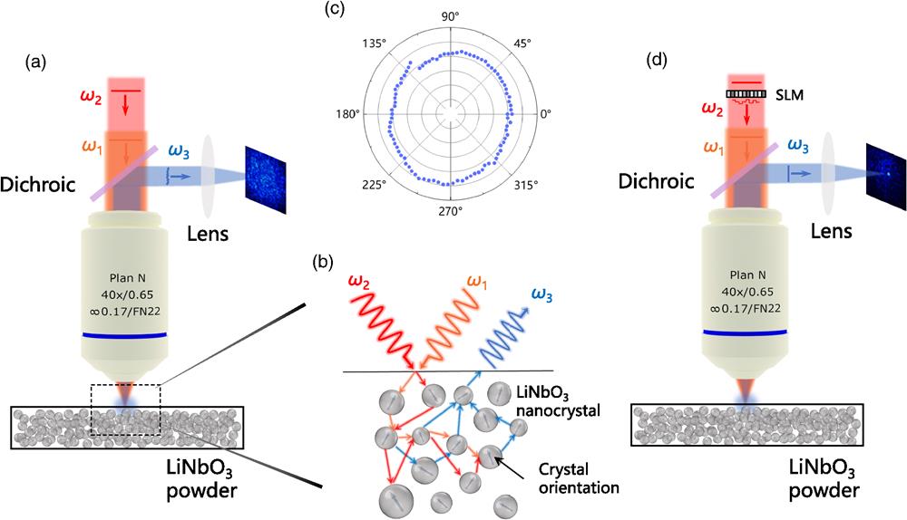
    The schematic of nonlinear signal focusing via wavefront shaping based on SM is shown in Fig. 1. The nonlinear signal is monitored in the backscattering configuration. Without shaping the wavefront of the input field Ein(ω2), the generated nonlinear signal is divergent and forms a speckle pattern, as shown in Fig. 1(a). Figure 1(b) shows the generation and scattering process of the nonlinear signal in the scattering medium, and the blue arrows indicate the crystal orientation of the lithium niobate (LN) nanoparticle. When Ein(ω1) and Ein(ω2) are incident in LN powder simultaneously, the particles radiate nonlinear signal, i.e., sum-frequency generation (SFG), and form a speckle pattern after scattering by the medium. Figure 1(c) shows the polarization dependence of the nonlinear field generated from the scattering medium. The isotropic response confirms the random nature of polarization distribution. It is worth noting that the intensity distribution of the nonlinear signals is related to the polarization of the input field. As shown in Fig. 1(d), a nonlinear focal spot would be achieved by appropriate wavefront shaping of the input field Ein(ω2), which is obtained by the optical phase conjugation method Ein(ω2)=conj(KNL)Etarget(ω3)/Ein(ω1), where Etarget(ω3) is the nonlinear target field and Ein(ω1) is a constant.

    Schematic of controlling nonlinear light in scattering medium via the scattering-matrix method. (a) Generation of nonlinear speckle pattern without shaping the wavefront of the input fields. (b) Nonlinear signals generation and scattering process in LN powder. (c) Intensity of nonlinear signal for a variable polarization of input field Ein(ω2). (d) Schematic of nonlinear signal focusing via WS technique. With an appropriate wavefront of Ein(ω2), a focal spot of nonlinear harmonic can be achieved.

    Figure 1.Schematic of controlling nonlinear light in scattering medium via the scattering-matrix method. (a) Generation of nonlinear speckle pattern without shaping the wavefront of the input fields. (b) Nonlinear signals generation and scattering process in LN powder. (c) Intensity of nonlinear signal for a variable polarization of input field Ein(ω2). (d) Schematic of nonlinear signal focusing via WS technique. With an appropriate wavefront of Ein(ω2), a focal spot of nonlinear harmonic can be achieved.

    3 Experimental Results

    Experimental measurement of the SM of the nonlinear scattering medium is illustrated in Fig. 2. The experiment detail is depicted in Fig. 2(a). Two linearly polarized continuous wave lasers at the wavelengths of λ1=780  nm and λ2=1064  nm are used as the light source. Then both laser beams are expanded by a pair of expander lenses with focal lengths of 30 and 200 mm to fit the apparatus of the objective lens. A half-wave plate (HWP) is used for polarization control of laser beam 2. Laser beam 2 is then modulated by a spatial light modulator (SLM) (UPOLabs, HDSLM80R), which has a resolution of 1920  pixels×1200  pixels. Then the two laser beams are combined by a dichroic mirror (DM1) and focused on the scattering medium of LN powder by an objective lens (40×, NA=0.65). The generated SFG signals (λ3=450  nm) are reflected by another dichroic mirror (DM2), collected by a lens L5 (f5=100  mm) and recorded by a charge-coupled device (CCD). The scattering quadratic medium is a 100-μm thick layer of LN nanocrystal powder, which is deposited on an indium tin oxide-coated glass substrate by the electrophoresis method. The transport mean free path of the scattering medium is measured to be 3.4  μm (see Sec. 2 in the Supplementary Material for detail). The inset of Fig. 2(a) is the scanning electron microscopy (SEM) image of the LN powder, which shows that the LN particles have a maximum size of 200  nm. Figures 2(b)2(d) illustrate the SM measurement process. The pixels of the SLM can be divided into two groups. The central region corresponds to the N input modes (N=256 in our experiment). The Hadamard bases of phase patterns are used, which has been demonstrated to improve fluence at the sample plane and the signal-to-noise ratio (SNR).21 The pixels displayed around the Hadamard pattern are used to generate a nonlinear reference field. Each input mode changes with four phase steps, i.e., 0, π/2, π, and 3π/2. After measuring the output nonlinear field response for all the 4N measurements, shown in Fig. 2(c), the SM elements of the nonlinear scattering medium, which contain the amplitude and phase modulation coefficients, are directly extracted from the output modes of nonlinear harmonic wave, SFG in the experiment via the FPIM, as shown in Fig. 2(d).

    The SM measurement process. (a) Experimental setup. L1 to L5, lenses, f1−5=30, 200, 30, 200, and 100 mm; HWP, half-wave plate; SLM, spatial light modulator; M1 and M2, reflecting mirrors; DM1 and DM2, dichroic mirrors; Obj., objective; F, filter; and CCD, charge-coupled device camera. Inset: SEM image of the LN powder (scale bar: 1 μm). (b) Phase pattern (Hadamard basis) displayed on the SLM, and each input mode is scanned from 0 to 3π/2 in 4 steps (0, π/2, π, and 3π/2). The pixels displayed around the phase pattern are used to generate nonlinear reference field. (c) Speckle pattern of nonlinear signal corresponding to each Hadamard basis. (d) The measured SM KNL connects the input modes (horizontal axis) and output modes (vertical axis). β and θ are the amplitude and phase of the element of KNL, respectively.

    Figure 2.The SM measurement process. (a) Experimental setup. L1 to L5, lenses, f15=30, 200, 30, 200, and 100 mm; HWP, half-wave plate; SLM, spatial light modulator; M1 and M2, reflecting mirrors; DM1 and DM2, dichroic mirrors; Obj., objective; F, filter; and CCD, charge-coupled device camera. Inset: SEM image of the LN powder (scale bar: 1  μm). (b) Phase pattern (Hadamard basis) displayed on the SLM, and each input mode is scanned from 0 to 3π/2 in 4 steps (0, π/2, π, and 3π/2). The pixels displayed around the phase pattern are used to generate nonlinear reference field. (c) Speckle pattern of nonlinear signal corresponding to each Hadamard basis. (d) The measured SM KNL connects the input modes (horizontal axis) and output modes (vertical axis). β and θ are the amplitude and phase of the element of KNL, respectively.

    To show the validity of the SM measurement, we present single-spot and double-spot focusing of a nonlinear signal on different positions at the region of interest (ROI). The CCD is divided into 16 superpixels × 16 superpixels via pixel binning, corresponding to M=256 output modes. For N=256 input modes, the matrix with a dimension of 256×256 is calculated after completing 1024 measurements; see Fig. 3(a). The nth column of the matrix represents the complex amplitude of nonlinear scattering field generated by the input field Ein(ω1) and the nth input mode of Ein(ω2). The calculated phase pattern of deterministic selective nonlinear focus on expected position is obtained by the phase conjugation of the corresponding row of the matrix, as shown in Fig. 3(b). The focal spots of SFG are located at different positions of ROI when the corresponding phase pattern is loaded on the SLM, as presented in Fig. 3(c). Figure 3(d) shows the intensity cross section of nonlinear focal spots located on different subregions (red, green, and blue curves). The nonlinear single focal spots have similar intensity and peak-to-background ratio (PBR) (defined by the ratio of the intensity at the focus to the mean intensity of the background speckle) is about 25. The energy of each focal spot of the double-spot focusing is lower than that in single-spot focusing because a similar amount of energy is distributed to two focal spots under the same number of input modes. The process is repeatable, which confirms the accuracy and stability of our system. The results can confirm the physical relevance of the measured SM.

    Reconfigurable focusing of nonlinear signals via wavefront-shaping method based on SM. (a) Measured SM that connects the input modes (horizontal axis) and output nonlinear modes (vertical axis). Hue and brightness represent phase and amplitude, respectively. (b) Calculated phase patterns for focusing nonlinear signals on different positions of the ROI with superpixel coordinates (3, 5) (red); (9, 9) (blue); (6, 3), and (6, 7) (green, double spots). (c) Focal spots located at different subregions of the ROI with the corresponding optimized phase patterns. (d) Intensity cross section of the nonlinear focal spots located on different subregions of the ROI (red, green, and blue curves).

    Figure 3.Reconfigurable focusing of nonlinear signals via wavefront-shaping method based on SM. (a) Measured SM that connects the input modes (horizontal axis) and output nonlinear modes (vertical axis). Hue and brightness represent phase and amplitude, respectively. (b) Calculated phase patterns for focusing nonlinear signals on different positions of the ROI with superpixel coordinates (3, 5) (red); (9, 9) (blue); (6, 3), and (6, 7) (green, double spots). (c) Focal spots located at different subregions of the ROI with the corresponding optimized phase patterns. (d) Intensity cross section of the nonlinear focal spots located on different subregions of the ROI (red, green, and blue curves).

    The single-spot and double-spot focusing experiments demonstrate the validity of the SM method; that is, the SM effectively characterizes the relationship between the nonlinear output field and the input pump field. In a multiple scattering regime, statistical properties of the SM of linear scattering medium follow the RMT.21 Theoretically, the measured SM of nonlinear scattering medium is also related to the SM, and similarly, we show that the statistical properties of the SM also follow the RMT. This can be inferred from the fact that a random system dominated by multiple scattering can be described by a random matrix of independent identically distributed entries of Gaussian statistics under certain conditions.21Figures 4(a) and 4(b) show the statistical distributions of the real and imaginary parts of the SM, respectively. Both obey the Gaussian statistics of the same distribution.

    Statistical properties of the SM: distribution of the (a), (b) real and imaginary parts of the measured SM and (c) the normalized singular value of the SM. The blue dashed line represents the singular value distribution from the quarter-circle law. Inset: normalized singular value of the matrix after removing the neighboring element. (d) Normalized amplitude profile of the focusing operator KNL conj(KNL).

    Figure 4.Statistical properties of the SM: distribution of the (a), (b) real and imaginary parts of the measured SM and (c) the normalized singular value of the SM. The blue dashed line represents the singular value distribution from the quarter-circle law. Inset: normalized singular value of the matrix after removing the neighboring element. (d) Normalized amplitude profile of the focusing operator KNLconj(KNL).

    Singular value decomposition (SVD) is a powerful tool to analyze the SM, which has been used to identify transmission eigenchannels25 and for selective focusing.26,27 For a multiple scattering medium, statistical distribution of the singular value of the SM follows the quarter-circle law.21 To facilitate comparison with the theoretical singular value of RMT, the singular value λi is normalized via λi˜=λi/j=1Nλj2/N. The normalized singular value of the measured SM and the theoretical prediction of RMT are shown in Fig. 4(c). It is noticeable that the statistics does not follow the quarter-circle law. One reason for this deviation may be the correlation between neighboring elements of the SM. Verifiably, the correlation is removed by considering only one element out of two, and the singular value distribution of the new downsampling SM is closer to quarter-circle law, as shown in the inset of Fig. 4(c). It is worth noting that the largest singular value deviates far from others, as marked by the red circle in Fig. 4(c). In a linear multiple scattering system, the existence of ballistic contributions would give rise to large singular values.5 Correspondingly, in a nonlinear scattering medium, a large singular value is attributed to the presence of nonlinear ballistic photons, i.e., single scattering nonlinear photons. However, the deviation of quarter-circle law and the presence of nonlinear ballistic photons do not significantly affect the ability of SM to focus scattering nonlinear fields. Figure 4(d) shows the normalized amplitude of the focusing operator KNLconj(KNL), which characterizes the capacity of SM to focus the output scattering field. The diagonally dominant distribution of the focusing operator signifies the ability of focusing at any position of the ROI through the scattering medium.

    Dynamic control of focusing light is extremely important in many fields, such as scanning near-field optical microscopy28 and atomic force microscopy.29 Realization of all-optical signal scanning through scattering media would further improve the imaging resolution.30 We experimentally realize point-by-point scan of nonlinear focus along predefined trajectories. Figure 5(a) shows the predefined S-shape scan trajectory of the nonlinear focus. The direction of the white arrow represents the scanning direction. The nonlinear focus of each position in the scanning path is shown in Fig. 5(b). The intensity and size of the focal spot maintain good uniformity. The nonlinear focus spot moves along the predefined scan path when the phase pattern on the SLM is defined, and the scanning speed of the nonlinear focus is 60 Hz, which is only limited by the frame rate of the SLM. The actual scan trajectory of the focus is shown in Fig. 5(c). Other predefined and actual scan trajectories of the nonlinear focus with the shape of the letters “J,” “T,” and “U” are shown in Figs. 5(d) and 5(e), respectively. The results provide a new solution for realization of high spatial resolution point-by-point scanning microscopic imaging, particles trapping31 through high-scattering media.

    Nonlinear focusing along predefined trajectories. (a) Predefined scan trajectory in the shape of the letter “S” of the nonlinear focus. The scanning direction is marked by the arrow. (b) Nonlinear focus of each position in the scan path at different times. (c) Actual trajectory of the nonlinear focus in the shape of the letter “S.” (d) Predefined scan trajectories in the shape of the letters “J,” “T,” and “U.” (e) Actual trajectory of the nonlinear focus in the shape of the letters “J,” “T,” and “U.”

    Figure 5.Nonlinear focusing along predefined trajectories. (a) Predefined scan trajectory in the shape of the letter “S” of the nonlinear focus. The scanning direction is marked by the arrow. (b) Nonlinear focus of each position in the scan path at different times. (c) Actual trajectory of the nonlinear focus in the shape of the letter “S.” (d) Predefined scan trajectories in the shape of the letters “J,” “T,” and “U.” (e) Actual trajectory of the nonlinear focus in the shape of the letters “J,” “T,” and “U.”

    4 Discussion

    We have presented an approach for measuring the SM in the scattering materials with nonlinearity. Compared with feedback algorithm, the SM-based WS method can greatly improve the speed. The feedback algorithm takes a great deal of time during the optimization. However, the SM method uses a set of predefined measurement patterns as phase masks, which allows the SLM to display all phase masks at its maximum frame rate without feedback. For N=256, the 1024 measurements for SM calculation take about 3 min, limited by the frame rate of the SLM and the CCD. High-speed SLM and photodetectors are expected to shorten the SM measurement time down to the microsecond scale.4 Unlike its linear counterparts, the SNR is limited by the second-order susceptibility and input power in the nonlinear regime. Nonlinear scattering materials with larger second-order susceptibility, such as cadmium germanium arsenide, thallium arsenic selenide, and gallium arsenide, and using more intense lasers are conducive for higher SNR. Many wavefront-shaping techniques based on feedback algorithms can only be realized through optimization by reiteration. On the contrary, such SM method can realize different tasks after one single measurement.

    Theoretically, the PBR of a nonlinear focus equals that in a linear case and is expected to be N. However, we observe that the obtained PBR is lower than that in the linear case for the same input mode. Apart from facts of wavefront distortion due to dead zones of SLM, noise in the measurement, phase-only modulation, discrete phase modulation, and nonuniform illumination,32 the most significant reasons for this result are as follows: (i) the presence of the reference field increases the background; (ii) the nonlinear conversion efficiency of the nonlinear scattering medium is relatively low, and the nonlinear signal intensity generated by different incident modes may not be uniform, inevitably introducing measurement errors of the SM. It is worth mentioning that the measurement method is not only applicable to backscattering configurations but also to transmission configuration. This issue can be easily solved by switching the backscattering configuration to the transmission configuration.

    The establishment of the SM also provides a new and powerful method for nonlinear signal information processing in a strongly scattering environment. The establishment of the SM helps us to further understand the scattering characteristics in the nonlinear scattering medium and further expands its application scenarios. By utilizing the nanoscale probe,33 the scattering nonlinear signals may be expected to focus inside a scattering medium.34 Combining the WS technique with the point-spread function engineering method,35 it is expected that the scattering nonlinear signals can be focused into a variety of novel beams. Polarization control of nonlinear scattering signals is expected to be achieved by measuring the vector SM.8 In addition, the SM method may be pioneering new ways for nonlinear imaging through scattering media. As a proof-of-principle experiment, we only present the measurement of the SM in the SFG process. Such SM method can be extended to other nonlinear processes, such as second-harmonic generation, third-harmonic generation, four-wave mixing, and stimulated Raman scattering with proper configurations. The SM proposed may also provide a solution for quantum information restoration and long-distance quantum imaging in a strong scattering environment. Furthermore, the proposed SM method is expected to be applied to the field of micro- and nanophotonics in the future. Currently, many metasurface-based nonlinear wavefront controls have been proposed.36,37 However, most of these nonlinear metasurfaces are static and cannot modulate the nonlinear signals dynamically. By combining metasurface-based SLMs,38 SM measurements of static nonlinear metasurfaces can be realized to achieve dynamic modulation of nonlinear signals.

    5 Conclusion

    We have demonstrated nonlinear harmonic wave manipulation in a nonlinear scattering medium via the SM method. To illustrate its validity and accuracy, we have realized the nonlinear signal single-spot, multispot focusing, and dynamic focusing like scan along predefined trajectories. Moreover, we have shown that the statistical properties of the SM still follow the RMT. Our work provides a significant and meaningful tool for nonlinear signal recovery, nonlinear microscopic imaging and detection, microscopic object tracking through scattering media, and complex environment quantum information processing.

    Fengchao Ni is a PhD student in the School of Physics and Astronomy at Shanghai Jiao Tong University (SJTU). He received his bachelor’s degree from the School of Information and Optoelectronic Science and Engineering at South China Normal University in 2019. His research focuses on nonlinear optics.

    Haigang Liu received his PhD from Shanghai Jiao Tong University. He has been working as an assistant researcher since July 2020. His research focuses on nonlinear optics, micro-nano photonics, information optics and other fields to achieve light field manipulation research.

    Yuanlin Zheng is a professor in the School of Physics and Astronomy at SJTU. He obtained his PhD in optics from SJTU in 2013 and subsequently worked as a postdoctoral, assistant, and associate researcher in LAPMP at SJTU. His research focuses on nonlinear optics and integrated photonics for light-matter interaction and light manipulation applications.

    Xianfeng Chen is a distinguished professor in the School of Physics and Astronomy at SJTU. He obtained his PhD in physics at SJTU in 1999. He is the executive director of the Research Center for Optical Science and Engineering at SJTU. His current research focuses on advanced photonics materials and devices, nonlinear optics, nanophotonics, quantum optics, and ultrafast optics.

    References

    [1] J. W. Goodman. Some fundamental properties of speckle. J. Opt. Soc. Am., 66, 1145-1150(1976).

    [2] I. M. Vellekoop, A. P. Mosk. Focusing coherent light through opaque strongly scattering media. Opt. Lett., 32, 2309-2311(2007).

    [3] I. M. Vellekoop, A. Lagendijk, A. P. Mosk. Exploiting disorder for perfect focusing. Nat. Photonics, 4, 320-322(2010).

    [4] O. Tzang et al. Wavefront shaping in complex media with a 350 kHz modulator via a 1D-to-2D transform. Nat. Photonics, 13, 788-793(2019).

    [5] S. Popoff et al. Image transmission through an opaque material. Nat. Commun., 1, 81(2010).

    [6] D. Stellinga et al. Time-of-flight 3D imaging through multimode optical fibers. Science, 374, 1395-1399(2021).

    [7] R. Cao et al. High-resolution non-line-of-sight imaging employing active focusing. Nat. Photonics, 16, 462-468(2022).

    [8] H. B. de Aguiar, S. Gigan, S. Brasselet. Polarization recovery through scattering media. Sci. Adv., 3, e1600743(2017).

    [9] R. J. Tran, K. L. Sly, J. C. Conboy. Applications of surface second harmonic generation in biological sensing. Ann. Rev. Anal. Chem., 10, 387-414(2017).

    [10] C. Schlickriede et al. Nonlinear imaging with all-dielectric metasurfaces. Nano Lett., 20, 4370-4376(2020).

    [11] A. V. Kachynski et al. Photodynamic therapy by in situ nonlinear photon conversion. Nat. Photonics, 8, 455-461(2014).

    [12] J. Demas et al. Intermodal nonlinear mixing with Bessel beams in optical fiber. Optica, 2, 14-17(2015).

    [13] L. G. Wright, D. N. Christodoulides, F. W. Wise. Controllable spatiotemporal nonlinear effects in multimode fibres. Nat. Photonics, 9, 306-310(2015).

    [14] T. Čižmár, K. Dholakia. Shaping the light transmission through a multimode optical fibre: complex transformation analysis and applications in biophotonics. Opt. Express, 19, 18871-18884(2011).

    [15] B. G. Saar et al. Video-rate molecular imaging in vivo with stimulated Raman scattering. Science, 330, 1368-1370(2010).

    [16] J. D. Bhawalkar et al. Two-photon photodynamic therapy. J. Clin. Laser Med. Surg., 15, 201-204(1997).

    [17] Y. Qiao et al. Second-harmonic focusing by a nonlinear turbid medium via feedback-based wavefront shaping. Opt. Lett., 42, 1895-1898(2017).

    [18] O. Tzang et al. Adaptive wavefront shaping for controlling nonlinear multimode interactions in optical fibres. Nat. Photonics, 12, 368-374(2018).

    [19] H. Frostig et al. Focusing light by wavefront shaping through disorder and nonlinearity. Optica, 4, 1073-1079(2017).

    [20] M. Nixon et al. Real-time wavefront shaping through scattering media by all-optical feedback. Nat. Photonics, 7, 919-924(2013).

    [21] S. M. Popoff et al. Measuring the transmission matrix in optics: an approach to the study and control of light propagation in disordered media. Phys. Rev. Lett., 104, 100601(2010).

    [22] A. Badon et al. Smart optical coherence tomography for ultra-deep imaging through highly scattering media. Sci. Adv., 2, e1600370(2016).

    [23] H. Yılmaz et al. Customizing the angular memory effect for scattering media. Phys. Rev. X., 11, 031010(2021).

    [24] H. Yılmaz et al. Angular memory effect of transmission eigenchannels. Phys. Rev. Lett., 123, 203901(2019).

    [25] M. Kim et al. Maximal energy transport through disordered media with the implementation of transmission eigenchannels. Nat. Photonics, 6, 581-585(2012).

    [26] S. M. Popoff, A. Aubry, G. Lerosey, M. Fink, A. C. Boccara, S. Gigan. Exploiting the time-reversal operator for adaptive optics, selective focusing, and scattering pattern analysis. Phys. Rev. Lett., 107, 263901(2011).

    [27] T. Chaigne et al. Controlling light in scattering media non-invasively using the photoacoustic transmission matrix. Nat. Photonics, 8, 58-64(2014).

    [28] X. Chen et al. Modern scattering-type scanning near-field optical microscopy for advanced material research. Adv. Mater., 31, 1804774(2019).

    [29] M. Krieg et al. Atomic force microscopy-based mechanobiology. Nat. Rev. Phys., 1, 41-57(2019).

    [30] B. D. F. Casse et al. Super-resolution imaging using a three-dimensional metamaterials nanolens. App. Phy. Lett., 96, 023114(2010).

    [31] C. Min et al. Focused plasmonic trapping of metallic particles. Nat. Commun., 4, 2891(2013).

    [32] A. M. Paniagua-Diaz, W. L. Barnes, J. Bertolotti. Wavefront shaping to improve beam quality: converting a speckle pattern into a Gaussian spot(2021).

    [33] C. L. Hsieh et al. Digital phase conjugation of second harmonic radiation emitted by nanoparticles in turbid media. Opt. Express, 18, 12283-12290(2010).

    [34] I. M. Vellekoop et al. Demixing light paths inside disordered metamaterials. Opt. Express, 16, 67-80(2008).

    [35] A. Boniface et al. Transmission-matrix-based point-spread-function engineering through a complex medium. Optica, 4, 54-59(2017).

    [36] M. L. Tseng et al. Vacuum ultraviolet nonlinear metalens. Sci. Adv., 8, eabn5644(2022).

    [37] L. Wang et al. Nonlinear wavefront control with all-dielectric metasurfaces. Nano Lett., 18, 3978(2018).

    [38] S. Q. Li et al. Phase-only transmissive spatial light modulator based on tunable dielectric metasurface. Science, 364, 1087-1090(2019).

    [39] M. Baudrier-Raybaut et al. Random quasi-phase-matching in bulk polycrystalline isotropic nonlinear materials. Nature, 432, 374-376(2004).

    [40] M. P. Van Albada, A. Lagendijk. Observation of weak localization of light in a random medium. Phys. Rev. Lett., 55, 2692-2695(1985).

    [41] P. C. de Oliveira, A. E. Perkins, N. M. Lawandy. Coherent backscattering from high-gain scattering media. Opt. Lett., 21, 1685-1687(1996).

    [42] R. Sapienza et al. Anisotropic weak localization of light. Phys. Rev. Lett., 92, 033903(2004).

    Fengchao Ni, Haigang Liu, Yuanlin Zheng, Xianfeng Chen. Nonlinear harmonic wave manipulation in nonlinear scattering medium via scattering-matrix method[J]. Advanced Photonics, 2023, 5(4): 046010
    Download Citation