
Hua Kong, Wentao Sun, Huanping Zhou. Progress in flexible perovskite solar cells with improved efficiency[J]. Journal of Semiconductors, 2021, 42(10): 101605
- Journal of Semiconductors
- Vol. 42, Issue 10, 101605 (2021)
Abstract
1. Introduction
The development of photovoltaics that convert sunlight into electricity is a promising strategy to meet the rapidly growing energy needs. In the past few decades, silicon-based photovoltaic technology has made significant progress with respect to the cost and efficiency, which promoted clean energy production. Along with the advance of silicon solar cells, a variety of thin-film photovoltaics have been studied in order to further meet the application requirements of lightweight and low-cost. Especially in recent years, great interest in flexible and wearable electronic products has led to growing research activities on flexible and stretchable thin-film photovoltaic. Integrating these thin and soft solar collectors into walls, windows and portable objects will change the current way of energy production, reduce pollution, and greatly expand the usage scenarios and ways of obtaining energy.
Recently, the organic–inorganic hybrid perovskites have become the ideal candidate to develop flexible solar cells due to their excellent optoelectronic properties. In particular, due to its excellent light harvesting ability, only about 300 nm thick film is sufficient to absorb essentially all visible light above its band gap. Thus, ultra-thin and ultra-light solar cells can be prepared[
![]()
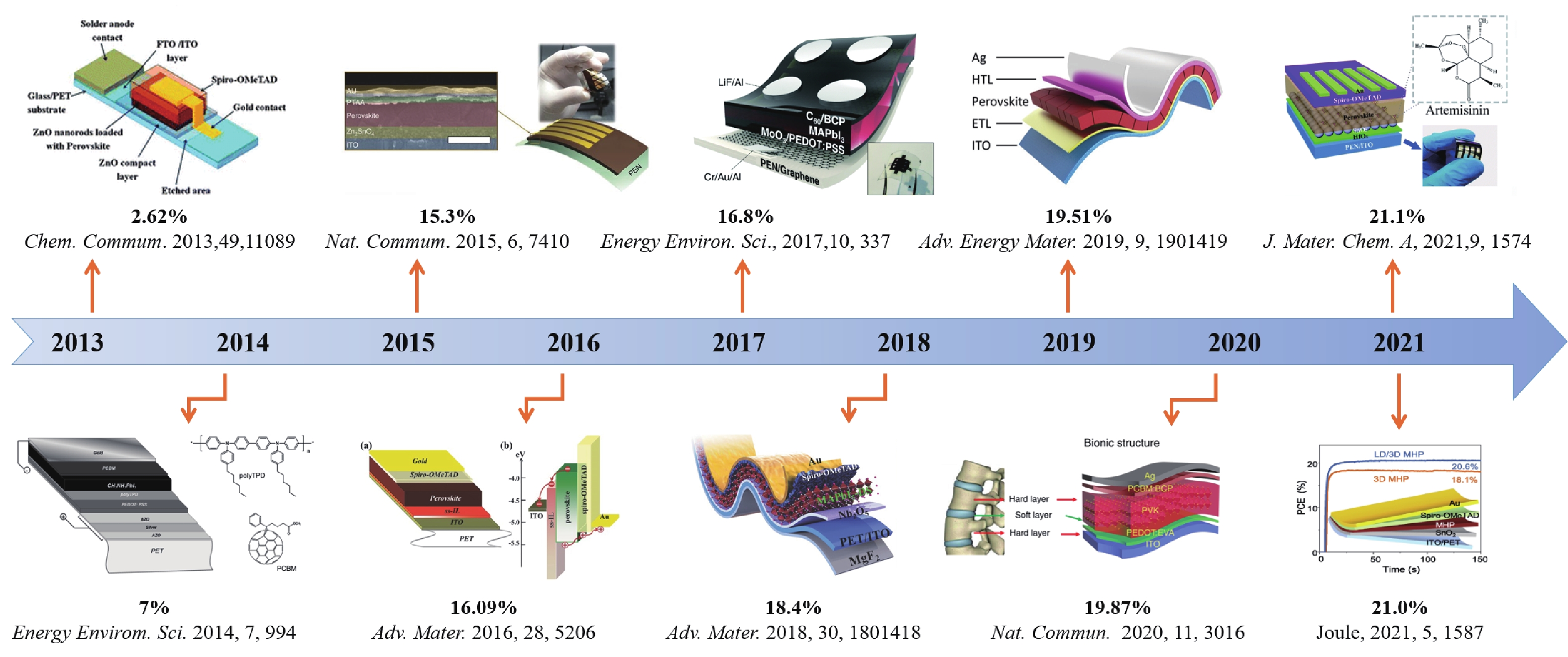
Figure 1.(Color online) The PCE evolution of FPSCs from 2013 to 2021[
FPSCs are mainly composed of substrate (PEN, PET, etc.), bottom electrode (FTO, ITO, etc.), electron transport layer (ETL), perovskite active layer, hole transport layer (HTL), and the counter electrode (Au, Ag, etc.). At present, the typical FPSCs structure are sandwich structure, in which the perovskite active layer is in the middle, with electron (or hole) blocking layers and electrodes on both sides. When the perovskite material is excited by light, it will produce photo-generated electron–hole pairs. Since the valence band maximum (VBM) of ETL is much lower than the VBM of perovskite materials, and their conduction band minimum (CBM) is at the same position, ETL plays the role of blocking holes and transporting electrons. The CBM of the HTL on the other side is much higher than the CBM of the perovskite material, and the positions of the VBM of them are the same, so the HTL plays the role of blocking electrons and transporting holes. The ETL and HTL are connected to the external circuit through the electrodes on both sides, which can realize the directional transfer of charges to form current.
Here we analyze the factors that affect the performance of FPSCs, mainly lies in 1) the roughness of the flexible substrate affects the quality of the perovskite film, 2) the high resistance and low light transmission of the flexible substrate lead to the low short-circuit current of the solar cell devices, 3) the permeability of the flexible substrate to water and oxygen results in long-term instability, 4) the mechanical stress occurred during the device fabrication brings into the fracture of perovskite layers. Then we summarized the development of flexible substrates, carrier transport layers, light absorption layers and electrodes to address the above concerns to improve the performance of flexible perovskite solar cells. Finally, we discussed the packaging process of FPSCs to further prolong the device's lifetime.
2. Performance improvement of flexible substrates
The most obvious difference between the flexible substrate and rigid substrate is whether the resulting devices can be bent and stretched. Its bending performance is mainly determined by the physical properties of the flexible substrate. An excellent flexible substrate is a basis for building a high-performance flexible perovskite solar cell. It should have the following characteristic. 1) Excellent mechanical properties, 2) Good optical properties: A suitable substrate should be transparent to the light absorption range of perovskite, particularly in the visible light region. 3) Good chemical properties: Because a variety of chemical compounds are used in the preparation of FPSC, the substrate should have chemical stability. 4) Blocking the permeation of oxygen and water: The permeation of oxygen and water is the main factor causing the performance degradation of perovskite solar cells. At present, the commonly used substrates for flexible perovskite solar cells include polymer substrates, metal substrates, ultra-thin flexible glass substrates and other special materials, etc.
2.1. Polymer substrates
Polymer substrates have been most widely used in FPSC due to their advantages of high light transmittance, high flexibility, low cost, and good chemical stability[
![]()
Figure 2.(Color online) High-efficiency FPSC based on PEN and PET substrates. (a) Schematic diagram of the FPSC structure based on a perovskite layer doped with artemisinin. (b)
2.2. Metal substrates
Compared with polymer substrates, metal foil has better thermal stability, flexibility and conductivity, which makes them promising flexible substrates for FPSCs. The metal foil is generally used as both the substrate and the electrode, thus simplifying the preparation process. Flexible perovskite solar cells need to have light transmission on at least one side, but the opacity of the metal foil requires the top electrode on the other side to have light transmission.
Ti foils is the most commonly used metal foil substrate in FPSCs due to the compatibility of Ti foils with the subsequent growth of TiO2 electron transport layer. In 2015, Lee et al. used Ti foil as a flexible substrate and fabricated a flexible perovskite solar cell device with a Ti/compact TiO2/mesoporous TiO2/perovskite/Spiro-OMeTAD/Ag structure for the first time, with an initial efficiency of 6.15%[
In addition to Ti foil, Cu foil is also used to prepare FPSCs. Ahmadi et al. prepared cuprous iodide on the copper foil by exposing the pre-cleaned Cu foil to iodine vapor, and then used it as the hole transport layer of FPSC. Using zinc oxide as the electron transport layer and sprayed silver nanowires as the top electrode, the maximum PCE of the device is 12.80%[
2.3. Ultra-thin flexible glass substrate
Ultra-thin flexible glass substrates retain most of the advantages of rigid glass substrates, such as resisting high temperatures, blocking moisture and oxygen, and high light transmittance. Tavakoli et al. used 50 μm thick willow glass as a flexible substrate for the first time to prepare a flexible perovskite solar cell with a PCE of 12.06%[
![]()
Figure 3.(Color online) (a) Schematic diagram of FPSC structure based on Ti foil. (b)
Compared with widely used polymer substrates, the more prominent advantage of ultra-thin flexible glass is its smooth and non-deformable surface at high temperatures. Based on this advantage, a large-area module (42.9 cm2) was prepared with an efficiency of 15.86%[
3. Carrier transport layer
The carrier transport layer in the perovskite solar cell plays an important role, which is responsible for extracting electrons and holes from the interface and transporting them to the corresponding electrodes[
3.1. Electron transport layer
The excellent electron transport layer (ETL) should have high electron mobility and high light transmittance. At the same time, the conduction band maximum of ETL is essential to match the energy level of the perovskite, which can effectively transport electrons and block holes.
Because of its high electron mobility and low-temperature processability, ZnO was first used as an electron transport layer to prepare FPSCs[
![]()
Figure 4.(Color online) (a) Flexible perovskite device diagram[
Although the ZnO has excellent electronic properties, there are hydroxyl or residual organic acetate ligands on its surface, which leads to charge recombination at the interface and poor quality of perovskite deposits. In addition, there is proton transfer reaction between ZnO and perovskite, which leads to decomposition reaction of interface[
Compared with ZnO, TiO2 has better environmental stability and better perovskite compatibility. However, the most efficient TiO2 electron transport layer needs to be obtained through an annealing process at 450 °C. In 2013, Doampo et al. first tried to use TiOx for p–i–n structured FPSC[
![]()
Figure 5.(Color online) (a) The first FPSC based on the TiO2 electron transport layer and (b) its
Compared with TiO2, SnO2 has a deeper conduction band and higher electron mobility. It is easy to process by solution method at low temperature, and it is more stable under illumination[
Zn2SnO4 is a new type of ETL for high-efficiency FPSC applications. Shin has developed a new route to synthesize highly dispersed Zn2SnO4 by the introduction of a Zn–N–H–OH complex derived from hydrazine via simple solution process at low temperature (90 °C)[
In addition to all these well-developed inorganic ETLs, Yoo et al. also demonstrated a simple interfacial layer that replaces TiO2 with C60 with the aid of polyethyleneimine ethoxylation (PEIE)[
The various electron transport layers described above are all prepared under low temperature processes. Among them, the widely used inorganic electron transport layer materials TiO2, SnO2 and ZnO have been successfully developed with low temperature preparation processes. ZnO, which is the most readily developed FPSCs electron transport layer material, is limited for further application by the decomposition reaction at the interface. To solve this problem, interface passivation, e.g. using PCBM or TiO2, become effective solution[
3.2. Hole transport layer
The hole transport layer (HTL) in FPSC is essentially to have hole extraction and hole transport capability, as well as bending durability. In the n–i–p structure, the hole transport layer does not need to be transported because that it does not hinder the light absorption of the perovskite. Spiro-OMeTAD, which is widely used in traditional n–i–p structured PSCs, can provide excellent performance[
![]()
Figure 6.(Color online) (a) Schematic diagram of the fabrication of nanostructured NiO
Docampo et al. used PET/ITO/poly(3,4-ethylenedioxythiophene):polystyrene sulfonate (PEDOT:PSS)/MAPbI3–xClx/PCBM/TiOx/Al device structure to obtain the first FPSC[
Poly[bis(4-phenyl) (2,4,6-trimethylphenyl) amine] (PTAA) is often used as HTM layer, since the film can be obtained by low-temperature spin coating that is compatible with FPSC preparation. Moreover, PTAA are of high conductivity and reliable durability. Unlike Spiro-OMeTAD, which requires doping to improve performance, undoped PTAA still performs well in high-efficiency PSC. For example, Qiu et al. prepared an FPSC based on the PET/ITO/TiO2/MAPbI3−xClx/PTAA/Au structure in 2015 and achieved a PCE of 13.5%[
4. High-quality perovskite films
As the light absorption layer, the quality of the perovskite film directly affects the performance of the flexible perovskite solar cells. Compared with the perovskite film prepared on the glass substrate, the quality of the perovskite film on the flexible substrate is different, which is limited by the high roughness and high thermal resistance of the flexible substrate. Because the resistance of the most widely used low-cost flexible polymer substrate will rise sharply when the temperature is higher than 150 °C, the development of flexible perovskite solar cells mainly focuses on the preparation of perovskite thin films at low temperature.
4.1. Perovskite film preparation method
4.1.1. Spin-coating
The quality of the perovskite film on the flexible substrate is generally not satisfactory because of the poor wettability and high roughness of the surface of the flexible substrate. Choosing an appropriate preparation process to control the nucleation and crystallization process of the film is the effective way to obtain a high-quality film. As a simple and effective method, the spin coating process can be adopted to the preparation of small-area devices and are able to obtain perovskite films with a wide range of thickness. In general, there are one-step and two-step spin coating methods.
In the one-step deposition method, the mixed precursor solution containing MA/FA halides and metal halides is directly deposited onto the desired substrates through a one-step spin-coating procedure. The sample is then annealed at low temperature (100–150 °C) to produce a perovskite film. The one-step spin coating process usually involves an anti-solvent. Cheng et al. added chlorobenzene (CB) as an effective anti-solvent during the spin-coating of perovskite in N, N-dimethylformamide (DMF) to prepare a highly uniform perovskite layer[
4.1.2. Scalable deposition method
Spin coating can effectively be used to produce a uniform perovskite layer on a small area, but this method is difficult to obtain a large area of uniform perovskite. In order to fabricate large-scale flexible perovskites, it is particularly important to use scalable printing technology to deposit perovskite absorbers. Among them, blade coating has become one of the promising laboratory technologies due to its easy handling and less waste of raw materials. In 2015, Jen et al. used a blade coating method to sequentially deposit poly(3,4-ethylenedioxy-thiophene): poly(4-styrenesulfonate) (PEDOT:PSS)/CH3NH3PbIXCl3–x/[6,6]-phenyl-C61-butyric acid methyl ester (PC61BM)/Bis-C60, the Ag was used as the top electrode in the device. The prepared FPSC exhibited a PCE of 7.14%[
![]()
Figure 7.(Color online) (a) Schematic diagram of the device prepared by blade coating method[
Vacuum thermal evaporation is a relatively mature technology that can deposit large-area and uniform thin films, and its relatively low temperature characteristics can also be compatible with the preparation process of FPSCs[
In perovskite roll-to-roll deposition compatible technology, gravure printing is continuous and stable. Seo et al. obtained a FAPbI3 film by gravure printing and soaked it in tert-butanol (tBuOH) to obtain a more uniform and highly crystalline film. The FPSC prepared entirely using the roll-to-roll process showed the best PCE of 13.8%[
The combination of slot-die coating and roll-to-roll process exhibits advantages, including less material waste, good film thickness control, one-dimensional patterning suitable for tandem interconnected cells without the need for a large number of patterning processes, and high manufacturing speed[
4.2. Composition engineering
Composition engineering has been proven to be an effective strategy to improve the quality of perovskite films. In 2017, Huang et al. proposed that the deposition conditions of the perovskite on the rigid substrate need to be optimized on the flexible substrate to improve the film morphology[
4.3. Additive engineering
The grain boundaries of perovskite, often as charge carrier recombination centers and ion migration channels, are currently an important factor affecting the efficiency and stability of PSCs[
Meng et al. incorporated a self-healing polyurethane (s-PU) with dynamic oxime-carbamate bonds in the grain boundaries of perovskite films. The s-PU could release the mechanical strain and repair cracks at the grain boundaries, which significantly improved the stretchability and deformability of perovskite films. The prepared FPSCs could recover 88% of initial PCEs after 1000 cycles at 20% stretching. In addition, due to the defect passivation of s-PU at the grain boundaries, the stretchable FPSCs exhibited a best efficiency of 19.15%[
5. Electrode
In order to absorb sufficient incident light, one of the two electrodes in the solar cell device should be transparent, while the other is usually opaque. For opaque electrodes, the metal foil conductive substrate has been introduced above. In addition, the evaporated thick metal film and printed carbon layer have also been mature and widely used. They possess the characteristic including good electrical conductivity, easy manufacturing, and appropriate energy levels that aligned with other functional layers of the device. In the transparent electrode, it is necessary to have the characteristics of high transparency, high conductivity, mechanical flexibility and chemical stability. ITO, which is widely used in glass substrates, has also been used in FPSCs. Apart from this, some new transparent electrodes, such as conductive polymers, ultra-thin metal films, Ag nanowires based electrodes, carbon nanotubes and graphene, have also been explored.
5.1. Indium tin oxide (ITO)
In the transparent electrode, ITO is the most commonly used material in FPSC, mainly because it is easy to obtain, and has good transmittance and conductivity. However, the high cost and high mechanical rigidity of ITO still plague the development of FPSCs. According to the published work, FPSCs based on ITO-PEN lose about 50% of the initial photoelectric conversion efficiency after a bending radius of 4 mm for 1000 cycles[
![]()
Figure 8.(Color online) (a) Resistance change of multilayer structure with bending cycle (Δ
In order to overcome the poor mechanical strength of ITO, some organic molecules or polymer scaffolds are used to improve the interface contact. Inspired by the flexible structure of vertebrae, Meng et al. designed an adhesive polymer interface layer (PEDOT:EVA, Poly(3,4-ethylenedioxythiophene): poly(ethylene-co-vinyl acetate)) (As shown in Fig. 8(d))[
5.2. Conductive polymer
PEDOT:PSS composed of conductive polymer PEDOT and water-dispersible PSS:PSS is by far the most successful and most widely used conductive polymer. PSS has the dual effects of doping charge and improving water solubility[
5.3. Ag-nanowire-based composites
Ag nanowires and grids have attracted widespread attention as alternative materials to ITO. Ag nanowire networks and Ag grids have good electrical conductivity, light transmittance and mechanical flexibility, which are used as transparent conductive electrodes in many optoelectronic devices. In FPSC, they are used solely or together with other materials as top or bottom transparent conductive electrodes. For example, a bare Ag nanowire grid is used as the top transparent conductive electrode of FPSC[
5.4. Carbon nanomaterials
Carbon nanomaterials have been used in rigid PSCs in different forms (such as carbon black/graphite composites, carbon nanotubes (CNT) and graphene) as back electrodes, partly because of their low cost and good electrical conductivity. Extensive research on carbon nanotubes and graphene electrodes is mainly based on their excellent properties, including good chemical stability, mechanical flexibility, high electrical conductivity and visible transparency. In 2014, the laminated CNTs network has been used as both the top electrode and the hole transport material in rigid PSC[
Graphene was first used as an interfacial layer in FPSC with an ITO-PET substrate in 2015[
6. Encapsulation methods
While the PCE is a crucial criterion to evaluate the performance of a PSC, the lifetime is also important standard since perovskite materials are very sensitive to many stressors, e.g. moisture, oxygen, light, heat, etc.[
As an efficient encapsulation material, various factors need to be considered: light transmission, oxygen transmission rate (OTR), water vapor transmission rate (WVTR), resistance to ultraviolet (UV), chemical inertness, mechanical flexibility, and strength, etc.
The combination of polyurethane resin encapsulation and Cr2O3-Cr interlayer proves that the air stability of ultra-thin FPSC has been improved. In particular, it was found that the use of a chromium oxide-chromium intermediate layer can effectively protect the metal top contact from the perovskite reaction, which is beneficial to prolong the long-term stability[
Nanocone PDMS has anti-reflection and waterproof functions and is attached to the front of the flexible substrate. These nanocone PDMS packaging materials help improve optical transmittance and achieve waterproof effects[
7. Conclusion and outlook
Organic–inorganic halide perovskite has become a promising candidate for flexible solar cells due to its excellent optoelectronic performance, excellent mechanical tolerance and low-temperature solution processability. Facilitated by the endeavor on exploration of flexible substrate, charge transport layer, high-quality perovskite film and transparent top electrode, the highest PCE of flexible PSCs reached 21.1%.
For the flexible substrates, the polymer substrates based FPSCs show the best PCE, but bring to poor environmental stability. Metal substrates, ultra-thin flexible glass substrates and other special materials, etc. have been explored to improve the device stability.
For the charge transport layer in FPSCs, the main focus is developing low-temperature process approach. At present, SnO2 is the best choice for electron transport layer in n–i–p structure due to its better stability and low-temperature processability.
For perovskite films, efforts have been devoted to the preparation of dense, uniformly covered, and high-quality films on flexible substrates. In terms of thin film growth, the spin coating is suitable for small-area device, but limited for large scale production. Component and additive engineering are indispensable in thin film fabrication, which can effectively passivate defects and improve crystal crystallization. Also, the band structure and mechanical property of perovskite layers can dramatically influence the photovoltaic performance of the resultant PSCs under mechanical strain.
For transparent conductive electrodes, ITO is the most common choice, but silver nanowires and carbon materials also become promising alternatives. Benefiting from its better mechanical flexibility, FPSCs based on silver nanowires and carbon materials show better bending stability.
The further development of FPSCs is discussed in the following aspects. 1) Preparation of large area solar cell modules. So far, the reported FPSCs with excellent PCE are all prepared by spin coating, and the effective area is small. With the increase of device area, more stringent requirements are posed on the quality of the perovskite film, and the density and uniformity of other functional layers (carrier transport layer and perovskite layer) are also crucial. While methods such as doctor blade coating, thermal deposition, and gravure printing can be selected for large-scale production, the roll-to-roll manufacturing technology may be an effective way to develop large-area FPSCs. 2) The environmental instability is also the most challenging issue for the development of FPSCs. In addition to the device degradation under heat, light, and electricity stressors, the polymer substrate of FPSCs accelerates the permeation of water and oxygen, which further brings to water and oxygen instability. It thus requires more robust encapsulation approach to fabricate FPSCs with improved long term stability. 3) In addition to improve the PCE, it is also necessary to pay attention to mechanical stability of FPSCs, since the application scenarios of FPSCs include wearable devices. Exploring flexible transparent electrodes with high conductivity and transmittance, low cost, and scalable processability is still an urgent need to meet the commercialization goal.
References
[1] M Graetzel, R A J Janssen, D B Mitzi et al. Materials interface engineering for solution-processed photovoltaics. Nature, 488, 304(2012).
[2] W Chen, Y Wu, Y Yue et al. Efficient and stable large-area perovskite solar cells with inorganic charge extraction layers. Science, 350, 944(2015).
[3] H Chen, F Ye, W T Tang et al. A solvent- and vacuum-free route to large-area perovskite films for efficient solar modules. Nature, 550, 92(2017).
[4] H Tan, A Jain, O Voznyy et al. Efficient and stable solution-processed planar perovskite solar cells via contact passivation. Science, 355, 722(2017).
[5] A Kojima, K Teshima, Y Shirai et al. Organometal halide perovskites as visible-light sensitizers for photovoltaic cells. J Am Chem Soc, 131, 6050(2009).
[6] L G Wang, H P Zhou, J N Hu et al. A Eu3+-Eu2+ ion redox shuttle imparts operational durability to Pb-I perovskite solar cells. Science, 363, 265(2019).
[7] Q Jiang, Y Zhao, X W Zhang et al. Surface passivation of perovskite film for efficient solar cells. Nat Photonics, 13, 460(2019).
[8] E H Jung, N J Jeon, E Y Park et al. Efficient, stable and scalable perovskite solar cells using poly(3-hexylthiophene). Nature, 567, 511(2019).
[9] D Weber. CH3NH3SnBr
[10] Weber D. CH3NH3PBX3, a Pb(II)-system with cubic perovskite structure. Zeitschrift Fur Naturforschung B, 33, 1443(2014).
[11] M Kim, G H Kim, T K Lee et al. Methylammonium chloride induces intermediate phase stabilization for efficient perovskite solar cells. Joule, 3, 2179(2019).
[12] J Burschka, N Pellet, S J Moon et al. Sequential deposition as a route to high-performance perovskite-sensitized solar cells. Nature, 499, 316(2013).
[13] H Zhou, Q Chen, G Li et al. Interface engineering of highly efficient perovskite solar cells. Science, 345, 542(2014).
[14] W S Yang, B W Park, E H Jung et al. Iodide management in formamidinium-lead-halide-based perovskite layers for efficient solar cells. Science, 356, 1376(2017).
[15] N J Jeon, J H Noh, W S Yang et al. Compositional engineering of perovskite materials for high-performance solar cells. Nature, 517, 476(2015).
[16] W S Yang, J H Noh, N J Jeon et al. High-performance photovoltaic perovskite layers fabricated through intramolecular exchange. Science, 348, 1234(2015).
[17] L K Yang, Q Xiong, Y B Li et al. Artemisinin-passivated mixed-cation perovskite films for durable flexible perovskite solar cells with over 21% efficiency. J Mater Chem A, 9, 1574(2021).
[18] M H Kumar, N Yantara, S Dharani et al. Flexible, low-temperature, solution processed ZnO-based perovskite solid state solar cells. Chem Commun (Camb), 49, 11089(2013).
[19] C Roldán-Carmona, O Malinkiewicz, A Soriano et al. Flexible high efficiency perovskite solar cells. Energy Environ Sci, 7, 994(2014).
[20] S S Shin, W S Yang, J H Noh et al. High-performance flexible perovskite solar cells exploiting Zn2SnO4 prepared in solution below 100 °C. Nat Commun, 6, 7410(2015).
[21] D Yang, R X Yang, X D Ren et al. Hysteresis-suppressed high-efficiency flexible perovskite solar cells using solid-state ionic-liquids for effective electron transport. Adv Mater, 28, 5206(2016).
[22] J Yoon, H Sung, G Lee et al. Superflexible, high-efficiency perovskite solar cells utilizing graphene electrodes: Towards future foldable power sources. Energy Environ Sci, 10, 337(2017).
[23] J S Feng, X J Zhu, Z Yang et al. Record efficiency stable flexible perovskite solar cell using effective additive assistant strategy. Adv Mater, 30, 1801418(2018).
[24] K Q Huang, Y Y Peng, Y X Gao et al. High-performance flexible perovskite solar cells via precise control of electron transport layer. Adv Energy Mater, 9, 1901419(2019).
[25] X C Meng, Z R Cai, Y Y Zhang et al. Bio-inspired vertebral design for scalable and flexible perovskite solar cells. Nat Commun, 11, 3016(2020).
[26] Q S Dong, M Chen, Y H Liu et al. Flexible perovskite solar cells with simultaneously improved efficiency, operational stability, and mechanical reliability. Joule, 5, 1587(2021).
[27] M Li, Y G Yang, Z K Wang et al. Perovskite grains embraced in a soft fullerene network make highly efficient flexible solar cells with superior mechanical stability. Adv Mater, 31, 1901519(2019).
[28] V Zardetto, T M Brown, A Reale et al. Substrates for flexible electronics: A practical investigation on the electrical, film flexibility, optical, temperature, and solvent resistance properties. J Polym Sci B, 49, 638(2011).
[29] M Lee, Y Jo, D S Kim et al. Flexible organo-metal halide perovskite solar cells on a Ti metal substrate. J Mater Chem A, 3, 4129(2015).
[30] M Lee, Y Ko, Y Jun. Efficient fiber-shaped perovskite photovoltaics using silver nanowires as top electrode. J Mater Chem A, 3, 19310(2015).
[31] M Lee, Y Ko, B K Min et al. Silver nanowire top electrodes in flexible perovskite solar cells using titanium metal as substrate. ChemSusChem, 9, 31(2016).
[32] J Troughton, D Bryant, K Wojciechowski et al. Highly efficient, flexible, indium-free perovskite solar cells employing metallic substrates. J Mater Chem A, 3, 9141(2015).
[33] G S Han, S Lee, M L Duff et al. Highly bendable flexible perovskite solar cells on a nanoscale surface oxide layer of titanium metal plates. ACS Appl Mater Interfaces, 10, 4697(2018).
[34] Y M Xiao, G Y Han, H H Zhou et al. An efficient titanium foil based perovskite solar cell: Using a titanium dioxide nanowire array anode and transparent poly(3, 4-ethylenedioxythiophene) electrode. RSC Adv, 6, 2778(2016).
[35] B Abdollahi Nejand, P Nazari, S Gharibzadeh et al. All-inorganic large-area low-cost and durable flexible perovskite solar cells using copper foil as a substrate. Chem Commun Camb Engl, 53, 747(2017).
[36] M M Tavakoli, K H Tsui, Q Zhang et al. Highly efficient flexible perovskite solar cells with antireflection and self-cleaning nanostructures. ACS Nano, 9, 10287(2015).
[37] X Z Dai, Y H Deng, C H van Brackle et al. Scalable fabrication of efficient perovskite solar modules on flexible glass substrates. Adv Energy Mater, 10, 1903108(2020).
[38] B Dou, E M Miller, J A Christians et al. High-performance flexible perovskite solar cells on ultrathin glass: Implications of the TCO. J Phys Chem Lett, 8, 4960(2017).
[39] K Mahmood, S Sarwar, M T Mehran. Current status of electron transport layers in perovskite solar cells: Materials and properties. RSC Adv, 7, 17044(2017).
[40] D Y Liu, T L Kelly. Perovskite solar cells with a planar heterojunction structure prepared using room-temperature solution processing techniques. Nat Photonics, 8, 133(2014).
[41] T Y Jin, W Li, Y Q Li et al. High-performance flexible perovskite solar cells enabled by low-temperature ALD-assisted surface passivation. Adv Opt Mater, 6, 1801153(2018).
[42] L J Zuo, Z W Gu, T Ye et al. Enhanced photovoltaic performance of CH3NH3PbI3 perovskite solar cells through interfacial engineering using self-assembling monolayer. J Am Chem Soc, 137, 2674(2015).
[43] R Azmi, C L Lee, I H Jung et al. Simultaneous improvement in efficiency and stability of low-temperature-processed perovskite solar cells by interfacial control. Adv Energy Mater, 8, 1702934(2018).
[44] R Azmi, W T Hadmojo, S Sinaga et al. High-efficiency low-temperature ZnO based perovskite solar cells based on highly polar, nonwetting self-assembled molecular layers. Adv Energy Mater, 8, 1701683(2018).
[45] J X Song, L J Liu, X F Wang et al. Highly efficient and stable low-temperature processed ZnO solar cells with triple cation perovskite absorber. J Mater Chem A, 5, 13439(2017).
[46] X K Huang, J Yang, S Mao et al. Controllable synthesis of hollow Si anode for long-cycle-life lithium-ion batteries. Adv Mater, 26, 4326(2014).
[47] J L Yang, B D Siempelkamp, E Mosconi et al. Origin of the thermal instability in CH3NH3PbI3 thin films deposited on ZnO. Chem Mater, 27, 4229(2015).
[48] P Docampo, J M Ball, M Darwich et al. Efficient organometal trihalide perovskite planar-heterojunction solar cells on flexible polymer substrates. Nat Commun, 4, 2761(2013).
[49] D Yang, R X Yang, J Zhang et al. High efficiency flexible perovskite solar cells using superior low temperature TiO2. Energy Environ Sci, 8, 3208(2015).
[50] Giacomo F Di, V Zardetto, A D'Epifanio et al. Flexible perovskite photovoltaic modules and solar cells based on atomic layer deposited compact layers and UV-irradiated TiO2 scaffolds on plastic substrates. Adv Energy Mater, 5, 1401808(2015).
[51] I Jeong, H Jung, M Park et al. A tailored TiO2 electron selective layer for high-performance flexible perovskite solar cells via low temperature UV process. Nano Energy, 28, 380(2016).
[52] Y Dkhissi, F Z Huang, S Rubanov et al. Low temperature processing of flexible planar perovskite solar cells with efficiency over 10%. J Power Sources, 278, 325(2015).
[53] N Ahn, K Kwak, M S Jang et al. Trapped charge-driven degradation of perovskite solar cells. Nat Commun, 7, 1(2016).
[54] P Qin, S Tanaka, S Ito et al. Inorganic hole conductor-based lead halide perovskite solar cells with 12.4% conversion efficiency. Nat Commun, 5, 3834(2014).
[55] B Wu, K W Fu, N Yantara et al. Charge accumulation and hysteresis in perovskite-based solar cells: An electro-optical analysis. Adv Energy Mater, 5, 1500829(2015).
[56] B J Kim, M C Kim, D G Lee et al. Interface design of hybrid electron extraction layer for relieving hysteresis and retarding charge recombination in perovskite solar cells. Adv Mater Interfaces, 5, 1800993(2018).
[57] C L Wang, D W Zhao, C R Grice et al. Low-temperature plasma-enhanced atomic layer deposition of tin oxide electron selective layers for highly efficient planar perovskite solar cells. J Mater Chem A, 4, 12080(2016).
[58] Q Jiang, L Q Zhang, H L Wang et al. Enhanced electron extraction using SnO2 for high-efficiency planar-structure HC(NH2)2PbI3-based perovskite solar cells. Nat Energy, 2, 16177(2017).
[59] M Park, J Y Kim, H J Son et al. Low-temperature solution-processed Li-doped SnO2 as an effective electron transporting layer for high-performance flexible and wearable perovskite solar cells. Nano Energy, 26, 208(2016).
[60] C L Wang, L Guan, D W Zhao et al. Water vapor treatment of low-temperature deposited SnO2 electron selective layers for efficient flexible perovskite solar cells. ACS Energy Lett, 2, 2118(2017).
[61] S S Shin, W S Yang, E J Yeom et al. Tailoring of electron-collecting oxide nanoparticulate layer for flexible perovskite solar cells. J Phys Chem Lett, 7, 1845(2016).
[62] J Ha, H Kim, H Lee et al. Device architecture for efficient, low-hysteresis flexible perovskite solar cells: Replacing TiO2 with C60 assisted by polyethylenimine ethoxylated interfacial layers. Sol Energy Mater Sol Cells, 161, 338(2017).
[63] J Chung, S S Shin, K Hwang et al. Record-efficiency flexible perovskite solar cell and module enabled by a porous-planar structure as an electron transport layer. Energy Environ Sci, 13, 4854(2020).
[64] X Yin, P Chen, M Que et al. Highly efficient flexible perovskite solar cells using solution-derived NiO
[65] H Zhang, J Q Cheng, F Lin et al. Pinhole-free and surface-nanostructured NiO
[66] J W Jo, M S Seo, M Park et al. Improving performance and stability of flexible planar-heterojunction perovskite solar cells using polymeric hole-transport material. Adv Funct Mater, 26, 4464(2016).
[67] W M Qiu, U W Paetzold, R Gehlhaar et al. An electron beam evaporated TiO2layer for high efficiency planar perovskite solar cells on flexible polyethylene terephthalate substrates. J Mater Chem A, 3, 22824(2015).
[68] C Bi, B Chen, H T Wei et al. Efficient flexible solar cell based on composition-tailored hybrid perovskite. Adv Mater, 29, 1605900(2017).
[69] M D Xiao, F Z Huang, W C Huang et al. A fast deposition-crystallization procedure for highly efficient lead iodide perovskite thin-film solar cells. Angew Chem, 126, 10056(2014).
[70] N J Jeon, J H Noh, Y C Kim et al. Solvent engineering for high-performance inorganic–organic hybrid perovskite solar cells. Nat Mater, 13, 897(2014).
[71] Z B Yang, C C Chueh, F Zuo et al. High-performance fully printable perovskite solar cells via blade-coating technique under the ambient condition. Adv Energy Mater, 5, 1500328(2015).
[72] Z Wang, L X Zeng, C L Zhang et al. Rational interface design and morphology control for blade-coating efficient flexible perovskite solar cells with a record fill factor of 81%. Adv Funct Mater, 30, 2001240(2020).
[73] C Chen, C Wu, X D Ding et al. Constructing binary electron transport layer with cascade energy level alignment for efficient CsPbI2Br solar cells. Nano Energy, 71, 104604(2020).
[74] D Luo, W Yang, Z Wang et al. Enhanced photovoltage for inverted planar heterojunction perovskite solar cells. Science, 360, 1442(2018).
[75] J Xi, K Xi, A Sadhanala et al. Chemical sintering reduced grain boundary defects for stable planar perovskite solar cells. Nano Energy, 56, 741(2019).
[76] M Z Liu, M B Johnston, H J Snaith. Efficient planar heterojunction perovskite solar cells by vapour deposition. Nature, 501, 395(2013).
[77] T Lei, F H Li, X Y Zhu et al. Flexible perovskite solar modules with functional layers fully vacuum deposited. Sol RRL, 4, 2000292(2020).
[78] Y Y Kim, T Y Yang, R Suhonen et al. Roll-to-roll gravure-printed flexible perovskite solar cells using eco-friendly antisolvent bathing with wide processing window. Nat Commun, 11, 5146(2020).
[79] Z C Yang, W J Zhang, S H Wu et al. Slot-die coating large-area formamidinium-cesium perovskite film for efficient and stable parallel solar module. Sci Adv, 7, eabg3749(2021).
[80] S Razza, S Castro-Hermosa, A Di Carlo et al. Research Update: Large-area deposition, coating, printing, and processing techniques for the upscaling of perovskite solar cell technology. APL Mater, 4, 091508(2016).
[81] C T Zuo, D Vak, D C Angmo et al. One-step roll-to-roll air processed high efficiency perovskite solar cells. Nano Energy, 46, 185(2018).
[82] Q D Tai, X Y Guo, G Q Tang et al. Antioxidant grain passivation for air-stable tin-based perovskite solar cells. Angew Chem Int Ed, 58, 806(2019).
[83] X C Meng, Z Xing, X T Hu et al. Stretchable perovskite solar cells with recoverable performance. Angew Chem Int Ed, 59, 16602(2020).
[84] B J Kim, D H Kim, Y Y Lee et al. Highly efficient and bending durable perovskite solar cells: Toward a wearable power source. Energy Environ Sci, 8, 916(2015).
[85] F Louwet, L Groenendaal, J Dhaen et al. PEDOT/PSS: Synthesis, characterization, properties and applications. Synth Met, 135/136, 115(2003).
[86] J Huang, P F Miller, J C de Mello et al. Influence of thermal treatment on the conductivity and morphology of PEDOT/PSS films. Synth Met, 139, 569(2003).
[87] M Kaltenbrunner, G Adam, E D Głowacki et al. Flexible high power-per-weight perovskite solar cells with chromium oxide–metal contacts for improved stability in air. Nat Mater, 14, 1032(2015).
[88] J Han, S Yuan, L N Liu et al. Fully indium-free flexible Ag nanowires/ZnO:F composite transparent conductive electrodes with high haze. J Mater Chem A, 3, 5375(2015).
[89] H Lu, J Sun, H Zhang et al. Room-temperature solution-processed and metal oxide-free nano-composite for the flexible transparent bottom electrode of perovskite solar cells. Nanoscale, 8, 5946(2016).
[90] K K Sears, M Fievez, M Gao et al. ITO-free flexible perovskite solar cells based on roll-to-roll, slot-Die coated silver nanowire electrodes. Sol RRL, 1, 1700059(2017).
[91] Y W Li, L Meng, Y Yang et al. High-efficiency robust perovskite solar cells on ultrathin flexible substrates. Nat Commun, 7, 10214(2016).
[92] H Bian, D L Bai, Z W Jin et al. Graded bandgap CsPbI2+
[93] Z Li, S A Kulkarni, P P Boix et al. Laminated carbon nanotube networks for metal electrode-free efficient perovskite solar cells. ACS Nano, 8, 6797(2014).
[94] X Y Wang, Z Li, W J Xu et al. TiO2 nanotube arrays based flexible perovskite solar cells with transparent carbon nanotube electrode. Nano Energy, 11, 728(2015).
[95] I Jeon, T Chiba, C Delacou et al. Single-walled carbon nanotube film as electrode in indium-free planar heterojunction perovskite solar cells: Investigation of electron-blocking layers and dopants. Nano Lett, 15, 6665(2015).
[96] Q Luo, H Ma, F Hao et al. Carbon nanotube based inverted flexible perovskite solar cells with all-inorganic charge contacts. Adv Funct Mater, 27, 1703068(2017).
[97] J Deng, L B Qiu, X Lu et al. Elastic perovskite solar cells. J Mater Chem A, 3, 21070(2015).
[98] S Ameen, M S Akhtar, H K Seo et al. An insight into atmospheric plasma jet modified ZnO quantum dots thin film for flexible perovskite solar cell: Optoelectronic transient and charge trapping studies. J Phys Chem C, 119, 10379(2015).
[99] Z K Liu, P You, C Xie et al. Ultrathin and flexible perovskite solar cells with graphene transparent electrodes. Nano Energy, 28, 151(2016).
[100] Q Luo, H Ma, Q Hou et al. All-carbon-electrode-based endurable flexible perovskite solar cells. Adv Funct Mater, 28, 1706777(2018).
[101] Q X Fu, X L Tang, B Huang et al. Recent progress on the long-term stability of perovskite solar cells. Adv Sci, 5, 1700387(2018).
[102] F Matteocci, L Cinà, E Lamanna et al. Encapsulation for long-term stability enhancement of perovskite solar cells. Nano Energy, 30, 162(2016).
[103] G S Han, J S Yoo, F D Yu et al. Highly stable perovskite solar cells in humid and hot environment. J Mater Chem A, 5, 14733(2017).
[104] J S Yoo, G S Han, S Lee et al. Dual function of a high-contrast hydrophobic-hydrophilic coating for enhanced stability of perovskite solar cells in extremely humid environments. Nano Res, 10, 3885(2017).

Set citation alerts for the article
Please enter your email address
© Copyright 2018-2021 | Chinese Laser Press. All Rights Reserved 沪ICP备15018463号-20