Fangchen Hu, Jorge A. Holguin-Lerma, Yuan Mao, Peng Zou, Chao Shen, Tien Khee Ng, Boon S. Ooi, Nan Chi. Demonstration of a low-complexity memory-polynomial-aided neural network equalizer for CAP visible-light communication with superluminescent diode[J]. Opto-Electronic Advances, 2020, 3(8): 200009-1
Copy Citation Text
Visible-light communication (VLC) stands as a promising component of the future communication network by providing high-capacity, low-latency, and high-security wireless communication. Superluminescent diode (SLD) is proposed as a new light emitter in the VLC system due to its properties of droop-free emission, high optical power density, and low speckle-noise. In this paper, we analyze a VLC system based on SLD, demonstrating effective implementation of carrierless amplitude and phase modulation (CAP). We create a low-complexity memory-polynomial-aided neural network (MPANN) to replace the traditional finite impulse response (FIR) post-equalization filters of CAP, leading to significant mitigation of the linear and nonlinear distortion of the VLC channel. The MPANN shows a gain in Q factor of up to 2.7 dB higher than other equalizers, and more than four times lower complexity than a standard deep neural network (DNN), hence, the proposed MPANN opens a pathway for the next generation of robust and efficient neural network equalizers in VLC. We experimentally demonstrate a proof-of-concept 2.95-Gbit/s transmission using MPANN-aided CAP with 16-quadrature amplitude modulation (16-QAM) through a 30-cm channel based on the 442-nm blue SLD emitter.
The surge of visible-light communication (VLC) derives from the ever-increasing demand of wireless network capacity and the limited spectral resources in the radiofrequency domain1. VLC offers high-speed and high-capacity data links, while being free from electromagnetic interference (EMI), becoming a suitable technology for complementing the fifth-generation (5G) or beyond-5G network2, 3. Furthermore, VLC has the potential to relieve the wireless communications from radiation-related concerns attributed to the millimeter wavelength infrastructure4.
In VLC systems, both the light emitters and detectors5-9 are key elements for achieving high-speed communication links. InGaN-based laser diodes (LDs) and light-emitting diodes (LEDs), including micro-LEDs, have been used in the vast majority of the high-speed VLC systems up to date, achieving multi-Gbit/s (multi-Giga-bit-per-second) data rates10-14. The third type of device known as the superluminescent diode (SLD) combines the advantageous characteristics of both LDs and the LEDs15-19: Low etendue, high optical power density, low temporal coherence, wide frequency bandwidth, and droop-free emission, which makes the SLD attractive for VLC and other applications20-22. The SLD has been utilized as a VLC transmitter by using non-return-to-zero on-off keying (NRZ-OOK)23, 24, which is, however, limited by the binary modulation capacity. With this motivation, advanced multi-carrier modulation schemes, such as discrete-multitone (DMT), have just been demonstrated using the SLD by our group, achieving multi-Gbit/s data rate25, 26. Nevertheless, SLD-based VLC systems require further understanding to develop a mature platform with potential commercial deployment.
The necessity for VLC transmission or applications under a high-attenuation channel inevitably requires a high signal amplitude, i.e., more than the 0.5 V used in previous demonstrations25, 26, to support the required signal-to-noise ratio (SNR) for effective signal transfer. In consequence, the increased signal amplitude will lead to nonlinear distortion. In this regard, DMT may not be the preferred solution due to the possibility to aggravate the nonlinear damage and decrease the available transmission rate caused by its high peak-to-average power ratio (PAPR) as a typical multi-carrier modulation format 27. To prevent the nonlinear distortion, an alternative to DMT is considered to be the carrierless amplitude and phase modulation (CAP) format, which previously lacked investigation in SLD-based VLC systems.
CAP as a single-carrier modulation scheme has been proposed in VLC depicting a lower complexity and an improved PAPR when compared to orthogonal frequency division multiplexing (OFDM) schemes (i.e. DMT)28. Moreover, by enhancing the CAP scheme with advanced equalization filters such as the deep neural network (DNN)29, the linear and nonlinear damage present in VLC links can be greatly reduced. This route offers significant potential for addressing the unknown linear and nonlinear noise in the SLD-based VLC system. However, standard DNNs may have a relatively high complexity induced by the fully-connected structure, representing a challenge to their implementation. Thus, a practical neural network with low complexity and excellent equalization performance is strongly needed.
Here, we design and propose an innovative memory-polynomial-aided neural network (MPANN) for the novel high-speed SLD-based VLC system with CAP modulation. We implement the MPANN as a post-equalization filter and study the necessity and efficiency of the MPANN equalizer by providing a comprehensive comparison of both the equalization performance and computation complexity between MPANN and other traditional CAP equalization schemes, including the least mean square (LMS) equalizer, the 2nd-order Volterra series (VOLT2) equalizer, the digital pre-distortion (DPD), and a standard DNN. As compared to the LMS equalizer, the MPANN provides up to 2.7 dB gain of Q factor, and as compared to the DNN, the MPANN shows equivalent Q factor with nearly a fifth of the spatial complexity. These results demonstrate the superior equalization performance and the practical low complexity of the developed MPANN equalizer. A proof-of-concept VLC transmission through a 30-cm free-space link based on a 442-nm blue SLD emitter achieves 2.95-Gbit/s using the MPANN-aided CAP modulation. The demonstration suggests that the MPANN equalizer is a promising option for a nonlinear VLC system, especially SLD-based VLC systems.
Principle
Blue superluminescent diode
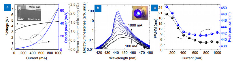
The SLD was fabricated by etching a c-plane GaN-based commercial laser epitaxial structure, designed with a facet tilting of 12°, and a ridge waveguide with a length of ~1 mm and a width of ~15 μm is similar to reported elsewhere23, 25. Figure 1(a-i) shows the electron microscope image of the SLD depicting the etched front facet. The device is mounted in a TO-56 brass holder for handling and heat management. Figure 1(a) shows the instantaneous light-output-power-current-voltage (L-I-V) characteristics under continuous wave (CW) injection current. The SLD is mounted in a thermoelectric cooler (TEC, SaNoor-SN-LDM-T) to keep the case temperature constant to 16 ℃, and the device is biased with a laser diode test system (Keithley 2520). The I-V curve shows a turn-on voltage around 3.4 V. A peak output power of 65 mW is measured at a current of 1 A (~6.7 kA/cm2 current density). The L-I curve depicts a linear regime corresponding to mostly spontaneous emission (1 mA to ~300 mA) followed by an exponential increase in the output power due to the amplified spontaneous emission (ASE) (~300 mA to ~800 mA) and later a superlinear regime (> 800 mA). The characteristics reveal a droop-free operation as seen from the external quantum efficiency (EQE) plotted in Fig. 1(a) as a dashed line.
Figure 1.SLD device and electro-optical characteristics.(a) Light-output-power – current – voltage (L–I–V) and external quantum efficiency (EQE) characteristics of the SLD at CW injection current. (i) Scanning electron microscope image of the SLD showing the metal contact (on p-side) and the 12° tilted front facet. (b) Electroluminescence (EL) spectra of the SLD under various injection currents. (ii) SLD under operation coupled with a collimating lens. (c) Full-width at half maximum (FWHM) and peak position of the SLD as measured from (b).
The electroluminescence spectra were measured with an optical spectrum analyzer (Yokogawa AQ6373B) at injection currents from 100 mA to 1000 mA as seen in Fig. 1(b). A peak wavelength emission at ~442 nm is observed with a full width at half maximum (FWHM) of ~8 nm to ~4 nm after the onset of the ASE. The working device, as mounted in the TEC and coupled to a collimation lens can be observed in Fig. 1(b-ii). The characterized FWHM and peak position of the SLD are plotted in Fig. 1(c). The 3-dB bandwidth of the SLD when the injection current is 700 mA is around 400 MHz measured by a network analyzer (NA, Agilent E8361C PNA). The specific measurement method is introduced in Ref.25.
CAP and MPANN equalizer
For traditional CAP, the finite impulse response (FIR) filter is usually used in the receiver side to mitigate the linear damage, such as the signal attenuation and the ISI from the channel and imperfect devices. However, a long filter length is usually needed for the FIR filter30, and it hardly handles the severe nonlinear effect existing implicitly in the high-speed VLC systems31. Thus, CAP modulation together with various advanced post-equalization methods has been proposed to comprehensively solve both the linear and the nonlinear damage in the VLC systems. Three major equalization schemes are reported in previous studies to reduce the ISI and the effect of the system nonlinearities: one is the LMS equalization by applying a long training sequence and LMS algorithm to mitigate the linear impairment; the second one is the VOLT2 which utilizes a similar training algorithm except that it involves adding the nonlinear input from Volterra series before the equalization; the third one is using a neural network (NN) for mitigating both the linear and nonlinear distortions. Among the NNs, the DNN, also called in some works as artificial NN (ANN) or multi-layer perceptron (MLP)31, is one of the NNs used for channel equalization due to its powerful nonlinear activation functions32 and its complex multi-layer structures.
Most of these advanced equalization schemes obtain the optimal equalization performance at the cost of computational complexity, hence, it is important to consider the trade-off between the performance and the complexity of the filters when a practical implementation is intended. For example, the DPD is believed to be an effective and popular method which simply uses the memory polynomial to shrink the equalization's complexity33, nonetheless, by neglecting the cross term of the polynomial expansion, DPD sacrifices a part of the equalization performance. Given the shortcomings and characteristics of the four schemes mentioned in this work (LMS, VOLT2, DNN, and DPD), as well as the electro-optical nonlinear characteristic of the SLD (Fig. 1(a)), we expect the best equalization performance to be obtained from designing a new robust equalizer with both advanced linear and nonlinear persistence while retaining an optimized low complexity.
By combining the theory of the DPD and MLP, a novel MPANN equalizer was designed on a three-layers structure, including a memory-polynomial layer (MP layer), a first hidden layer, and an output layer. Its structure is presented in Fig. 2(b). The 1st hidden layer is fully connected with the output layer and MP layer. Inside the MP layer, the input nodes are partially connected with the output nodes with the function of mapping its input data $\mathit{\boldsymbol{S}} = [{S_1}, {S_2}, ..., {S_m}]$ to Kin a higher data space dimension than S according to the memory polynomial nonlinear model32. The K is the output data of the MP layer and also serves as the input data of the 1st hidden layer. Comparing to the conventional structure of DNN that directly sends the coarse received signal samples S, adding the MP layer may significantly decrease the demanded nodes of the following MLP structure due to the aid of the prior knowledge of the nonlinear model. The detailed mapping rule of the MP layer is defined as:
Figure 2.(a) The schematic of the MPANN equalization pre-processing for the received symbols. (b) The structure of the applied MPANN. (c) The structure of the DNN for comparison.
where m and r represent the linear memory depth and nonlinear memory depth of the channel, respectively, which can be further studied in Ref.34. The increase in the numbers of m and r can enhance the equalization ability of MPANN, but the complexity of MPANN grows as well.
In order to apply MPANN at the receiver side, the first task is to estimate the optimal network weights W1 and W2. Once the optimal network weights are fixed, the received signal can be directly fed into MPANN, outputting the equalized signal. The universal method is to use a large train set and effectively train the neural network based on back-propagation (BP) algorithm to get the optimal network weights. The train set should comprise the known transmitted symbols and the corresponding received symbols from the receiver. During the training process, the long received-symbols $\mathit{\boldsymbol{X}} = [{X_1}, {X_2}, ..., {X_n}]$ from the train set first are converted to several short columns of sample symbols selected by a sliding window with the length of the value of linear memory depth m. As indicated in the data pre-processing step illustrated in Fig. 2(a), the first column (from right to left) of sample symbols is $[{X_1}, {X_2}, ..., {X_m}]$, the next one is $[{X_2}, {X_3}, ..., {X_{m + 1}}]$. When the sliding window moves downward, the i-th column of sample symbols becomes $[{X_i}, {X_{i + 1}}, ..., {X_{1 + m - 1}}]$. After the sliding window reaches the end of the received signal, all of the sample symbols are ready and act as a set of S fed into the MP layer of MPANN. In the MPANN shown in Fig. 2(b), the output of l-th layer is defined as: ${\mathit{\boldsymbol{H}}_l} = {[{H_1}, {H_2}, ..., {H_d}]^{\rm{T}}}$, and the network weight of l-th layer Wl can be expressed as:
where L stands for the number of layers of MPANN, d and q represent the node number of the l-th layer and the (l+1)-th layer. Thus, the output of (l+1)-th layer Hl+1 is:
$
Extra \left or missing \right \right.,
\end{array}
$
where f(x) is the rectified linear unit (ReLU) used as the activation function in MPANN, which has been verified to be better than other activation functions in the gradient propagation and computation35. The loss function used in MPANN is the mean square error (MSE), defined as:
where Y is the value of the estimated symbol for the received signal X outputted from MPANN. The Z is the correct label value of the estimated symbol Y. The B is the batch size. The Yi and Zi stand for the i-th estimated symbol and its label in one batch. Finally, the BP algorithm is utilized to carry out the training process to reduce the loss function by updating the network weights. Validation set and test set are also adopted to prevent the over-fitting problem and evaluate the performance of MPANN, respectively. During the training and test process of MPANN, the order of all samples in every batch is randomized to avoid the memory effect for PRBS sequence36. This method has been validated in VLC system in Ref.37. In order to accelerate the training process, the batch size, the epoch, the ratio of train set, validation set and test set are fixed to 256, 20, 30%, 20% and 50%, respectively, according to a practical optimized condition38. The subsequent step involves the received signals from the oscilloscope, which is the data set that needs to be equalized. These signals are fed into the pre-processing layer of the MPANN while the equalized signal is obtained from the output layer.
In order to verify the quality of the MPANN in the SLD-based VLC system, it should be fairly compared with LMS, VOLT2, DPD and DNN technology. Figure 2(c) is a typical structure of DNN equalizer with an input layer, a first hidden layer, a second hidden layer, and an output layer. The number of hidden layers and nodes of every layer is closely related to the performance and complexity of MLP that will be addressed in the next section. For LMS, VOLT2 and DPD equalization schemes, their typical structure can be studied in Refs.29, 33, 39, 40. Linear and nonlinear memory depths are their main parameters which should be discussed and manually fixed to an optimal value. Similar to the MPANN, the ratio of train set is fixed to 30% for all equalizers.
Experimental setup
The experimental setup and the schematic of the MPANN-aided CAP modulation SLD-VLC system are shown in Fig. 3. The pseudo-random binary sequence (PRBS) is initially generated and then mapped into the 16-QAM (quadrature amplitude modulation). After three times of up-sampling, the signal is split into the real and imaginary components. Each of the components is filtered by the in-phase fI and quadrature filter fQ, respectively. The in-phase and quadrature filter form the Hilbert filter, and their impulse response is given by the product of a square root raised cosine (SRRC) filter and cosine (real) and sine (imaginary) waves40. Finally, the real-value output signal of each filter is summed up becoming the time-domain signal that can be sent into an arbitrary waveform generator (AWG) (Tektronix-AWG70002A). The output electrical signal from the AWG is amplified by an electronic amplifier (MiniCircuits-ZHL-6A-S+) and coupled with direct current (DC) bias by a bias-tee (Tektronix-PSPL5580) to drive the SLD. A TEC-integrated mount (SaNoor-SN-LDM-T) is used to avoid the overheating of the SLD. Two collimation lenses and a neutral density (ND) filter are used in a 30 cm free-space transmission path. The modulated light from the emitter is received by a Si avalanche photodiode (APD) (MenloSystem-APD210) and transformed into an electrical signal. Finally, the signal is resampled by an oscilloscope (Tektronix-DPO72004C) to do further offline signal processing.
Figure 3.VLC experimental setup.(a) Schematic of the VLC system and the DNN-aided CAP post-equalizer. (b) Image of the optical channel and components. (c) and (d) are detail images of the transmitter (TX) and receiver (RX) units. CAP: Carrierless amplitude and phase. AWG: Arbitrary waveform generator. DC: Direct current. TEC: Thermoelectric cooler. APD: Avalanche photodiode. OSC: Oscilloscope.
At the digital signal processing (DSP) part, the MPANN serves as the first-stage equalizer to mitigate both the linear and nonlinear damage from the devices and channel. To highlight the role of the MPANN as a robust and relatively practical equalizer, the LMS, VOLT2, DNN and DPD equalizers are also set as the first-stage equalizers. After the equalization, the real and imaginary parts of the output signal are respectively filtered by two matching filters mfI and mfQ, given in Ref.39. After three times of down-sampling, the recovered complex signal is sent into the second-stage LMS linear equalizer to mitigate the residual linear noise from the first-stage equalization. Finally, the signal is recovered after QAM de-mapping and decoding. Such a two-stage equalization scheme has been proven to be a better equalization scheme than only one-stage equalization in high-speed VLC system39. In addition, to fairly evaluate the nonlinear persistence of different equalization schemes, nonlinear filters are utilized as the first-stage filter. Moreover, a first-stage nonlinear equalizer can prevent the in-phase/quadrature (I/Q) imbalance issues existed in the CAP modulation after optical transmission42.
Results and discussion
This section details the results of the SLD-based CAP VLC link and the fair comparison of MPANN with other equalization schemes based on their equalization performance and computation complexity.
First, we tested the BER performance under the different injection currents and the various peak-to-peak voltages (Vpp) simultaneously, as seen in Fig. 4(a). Approximately, an injection current of 700 mA and a Vpp of 500 mV define the best driving point for our SLD-based VLC system for current experimental devices. A higher transmission data rate could be derived for a Vpp higher than 500 mV according to the trend in Fig. 4(a), however, the utilized AWG imposes a limit to the maximum signal amplitude of 500 mV (Vpp) in our measurement.
Figure 4.(a) The relation of the injection current–Vpp–BER in the SLD-based VLC system. (b) The frequency response of the received signal (RX) and the transmitted signal (TX). (c) The constellation diagram of the recovered signal without the first-stage equalizer showing nonlinear effects at the data rate of 2.4 Gbit/s using the setup of Fig. 3.
Even though the bias point has been set up correctly, the nonlinear effect induced by the exponential behavior of the SLD's L-I-V relationship (Fig. 1(a)) and the nonlinear response of the APD continue to influence the transmission quality of the CAP signal. For example, distortion in the channel severely damages the SNR of the received signal, which can be clearly observed in the frequency response in Fig. 4(b). The damage of the SNR can also be reproduced from the time domain, such as the constellation diagram of the received signal presented in Fig. 4(c). Here, a CAP signal with 600 MHz bandwidth is transmitted through the channel, and only a second-stage LMS equalizer is utilized at the DSP part. It is clear that the outer ring of the constellation is strongly damaged by the nonlinear effect and residual linear noises, changing the normally spherical shape of the outer constellation cluster into an ellipsoidal shape. The evidence is purposely emphasized by a red oval in Fig. 4(c). Thus, a high-performance nonlinear equalizer and two-stage equalization scheme are necessary if a higher transmission data rate is required for the SLD-based VLC system.
In order to verify the MPANN as an effective first-stage nonlinear equalizer, three traditional linear and nonlinear equalization schemes, including LMS, Volterra-series and DPD technology, were investigated in an evaluation benchmark. Figure 5 shows the BER performance of LMS, VOLT2, and DPD under different linear and nonlinear memory depths when the bandwidth of a signal is 600 MHz and 700 MHz. It is clear that the equalization performance is improved if the linear and nonlinear memory depth increases, however, when increasing this memory depth, the improvement will eventually reach a plateau and converge to a constant. Thus, considering the trade-off between performance and complexity, 71, 71, and 31 are the optimal values of the linear memory depth for LMS, Volterra-series and DPD technology, respectively. 15 and 4 are the optimal values of the nonlinear memory depth respectively for Volterra-series and DPD technology. Here, the linear memory depth of the Volterra-series nonlinear equalizer is the same as that of the LMS linear equalizer because the training algorithm of the VOLT2 also works on the LMS algorithm. Also, while the optimal nonlinear memory depth of the signal with 600 MHz in VOLT2 is 9 instead of 15, the increase of the bandwidth to 700 MHz will bring severer nonlinear effect which requires a greater nonlinear memory depth. Hence, the optimal nonlinear memory depth in VOLT2 is better to be 15 referring to the case of 700 MHz for a high-speed transmission.
Figure 5.BER performance when using(a) LMS linear equalizer under different numbers of linear memory depth; (b) VOLT2 nonlinear equalizer under different numbers of nonlinear memory depth and fixed number of linear memory depth (71); (c) DPD under different numbers of linear memory depth and fixed number of nonlinear memory depth (4); (d) DPD when using different numbers of nonlinear memory depth and fixed number of linear memory depth (31). All the measurements are taken when the bandwidth of CAP-16-QAM is 600 MHz and 700 MHz. D: the optimal and utilized memory depth
Next, we try to find an optimal structure of DNN and MPANN to achieve a balance between complexity and performance. That is to say, all hyperparameters including the number of nodes in every layer, the number of the hidden layers in DNN and MPANN, and the linear and nonlinear memory depths in MPANN need to be discussed. The simultaneous iteration for all hyperparameters is time-costly while it can find the optimal results. Thus, the hyperparameters are optimized in the control variate technique, which means that one hyperparameters is investigated while the other hyperparameters are fixed. The hyperparameters that have been optimized maintain the optimal value. The hyperparameters that are waiting in line maintain a high value to avoid becoming the limited factor to the equalization performance of the MPANN. According to the results of Ref.43, a structure of MLP with two hidden layers offers a better performance than a structure with only one hidden layer. Moreover, a structure with three hidden layers produces limited gain when considering the increased complexity. Hence, we choose a two-hidden-layer structure for DNN. Only one hidden layer is applied to the MPANN according to the practical experience, minimizing the number of layers for an equalization performance similar to that of DNN.
Given the BER performance in Figs. 6(a)-6(c), the optimal node number of the first layer, the first hidden layer, and the second hidden layer of the DNN are 7, 128, and 4. For the MPANN with the results in Figs. 6(d)-6(f), the optimal linear and nonlinear memory depths in the MP layer are 15 and 4.The optimal number of nodes of the first hidden layer in MPANN is chosen as 5 to realize the lowest BER. Based on these parameters the MPANN and the DNN showed an equivalent BER performance as seen in Fig. 7(a), demonstrating robustness in mitigating the nonlinear effects of the VLC channel.
Figure 6.BER performance when varying(a) the number of nodes of the first layer of DNN, (b) the number of nodes of the first hidden layer of DNN, (c) the number of nodes of the second layer of DNN, (d) the linear memory depth of MPANN, (e) the nonlinear memory depth of MPANN, and (f) the number of nodes of the first hidden layer of MPANN when the bandwidth of CAP-16-QAM is 600 MHz and 700 MHz. N: The optimal and utilized number of nodes.
Figure 7.(a) Q factor performance comparison versus data rate with the equalization schemes of LMS, VOLT2, DPD, DNN and MPANN. (b) Spatial complexity comparison among the different equalization schemes.
Simultaneously, it is important to compare the computation complexity of all the equalization schemes used under their optimal structure. Usually, computation complexity is divided into time complexity and spatial complexity. Time complexity is difficult to be analyzed fairly for each equalization scheme, because it is not only related to the number of weights, but also is related to the optimization algorithm in the training process of every equalization scheme. However, the spatial complexity represents the required memory space for running each equalization scheme, which is a fair figure of merit to evaluate the complexity of equalization schemes for practical implementation and can be simply represented by the required number of weights to be updated in the training process. The structure and spatial complexity comparison of the investigated equalization schemes are all summarized in Table 1. The complexity can be calculated from the equation (1) in Ref.44 and the principle of NNs.
Equalization scheme
ML
MNL
M1
H1
H2
Spatial complexity
ML, MNL: the values of the linear and nonlinear memory depth. M1, H1, H2: the number of nodes in the input layer, the 1st hidden layer and the 2nd hidden layer
LMS
71
-
-
-
-
ML
VOLT2
71
15
-
-
-
ML + MNL(MNL + 1)/2
DPD
31
4
-
-
-
ML × MNL
DNN
-
-
7
128
4
M1×H1 + H1 × H2 + H2
MPANN
15
4
-
5
-
ML × MNL × H1 + H1
Table 1. Spatial complexity comparison of the equalization schemes.
We measured the achievable transmission data rate of CAP-16-QAM when MPANN and other equalization schemes serve as the first-stage equalizer. The results are shown in Fig. 7(a). The corresponding spatial complexity based on Table 1 is shown in Fig. 7(b). The Q factor is used as the figure of merit to evaluate the forward error correction (FEC) decoding performance that is proposed in Ref.45. From our results, the MPANN equalizer is proved to have a better performance than LMS, DPD, and VOLT2, and a gain in Q factor up to 2.7 dB is demonstrated at the data rate of 2.4 Gbit/s. Meanwhile, its spatial complexity is at least 4 times less than the one of the DNN and at the same order of magnitude as the VOLT2.
Even though the LMS, DPD, and VOLT2 also improve the constellation diagram (Figs. 8(a)-8(c)) as compared to the results in Fig. 4(c), it is possible to observe that there is still some residual linear and nonlinear distortion due to their limited equalization ability. LMS is only a linear equalizer without the ability to handle the nonlinear damage. DPD ignores the cross term of the nonlinear effect model which limits its performance. VOLT2 considers the cross term, but it can only deal with the 2nd-order nonlinear effect. On the other hand, DNN can easily generalize any equalization scheme for the unknown nonlinear effect in the VLC system, using the activation function (ReLU) and advance structure. However, DNN is always questioned about its high complexity. In our work, the DNN's spatial complexity is up to 1412, which is almost 9 times higher than that of VOLT2.
Figure 8.The constellation diagram of CAP-16-QAM at 2.4 Gbit/s using the setup in Fig. 3 when the first-stage equalization scheme is LMS, DPD, VOLT2, DNN and MPANN, respectively.
DNN needs a large number of layers and nodes as the consuming source to refine the optimal network weights from the coarse samples in a low data dimension. To eliminate complexity concerns, MPANN takes advantage of the prior knowledge of the nonlinear effect model to simplify its network structure. This approach lifts the original samples to a higher data dimension by memory polynomial expansion, helping the MPANN to find the optimal network weights easily and efficiently. We observe that the MPANN's small-size structure can achieve a performance equivalent to the DNN using nearly a fifth of the DNN's spatial complexity. To further explain why the MPANN outperforms other equalizers, two points can be mentioned: First, the neural structure and the advanced back-propagation algorithm have a more powerful ability to deal with classification and regression problems, on which the signal prediction is just a related application. Second, the use of prior knowledge from the nonlinearity model helps to reduce the number of layers and nodes needed for MPANN, resulting in a simplified structure and lower complexity as compared to DNN.
As a result, given the balance between performance and complexity, we propose MPANN as an efficient post-equalizer in the SLD-based VLC system. As seen in Fig. 7(a), a transmission data rate of up to 2.95 Gbit/s was demonstrated using the MPANN equalizer. This data rate represents an advantage of the SLD-based CAP-VLC systems over the LED-based counterparts39, paving the way for robust VLC technology, capable of delivering multi-Gbit/s systems based on SLD emitters, when it is deemed necessary.
Conclusions
The evolution of VLC as an attractive tool for the next generation of communications is based on its capability to provide multi-Gbit/s data rates while using unlicensed and interference-free channels, complementing the limited spectral resources of the conventional radio frequency regime. In this paper, we demonstrate a multi-Gbit/s VLC link using a novel MPANN-aided CAP modulation and a GaN-based SLD. We analyzed the communication performance of SLD-based CAP modulation using the MPANN as a post-equalizer. We compared the MPANN with equivalent LMS, 2nd-order Volterra-series, DPD and MLP (DNN) equalizers to measure the advantages and disadvantages of the MPANN in terms of data rate, correction of the linear and nonlinear distortion, and complexity. MPANN achieves Q factor gain of up to 2.7 dB higher than the LMS equalizer and complexity over 4 times less than that of DNN at a similar data rate. Such facts prove MPANN a low-complexity and practical equalizer for SLD-based VLC system. Using a 442-nm SLD emitter and given the superior performance of MPANN-aided CAP to resist the linear and nonlinear distortion, we successfully achieved up to 2.95 Gbit/s data rate in a VLC link through 30 cm free-space for a proof-of-concept demonstration.
Acknowledgements
This work was supported in part by the National Key Research, Development Program of China (2017YFB0403603), and the NSFC project (No. 61925104). JAHL, YM, TKN and BSO gratefully acknowledge the financial support from King Abdullah University of Science and Technology (KAUST) through BAS/1/1614-01-01, REP/1/2878-01-01, GEN/1/6607-01-01, and KCR/1/2081-01-01. This publication is partially supported by the King Abdullah University of Science and Technology (KAUST) Office of Sponsored Research (OSR) under Award No. OSR-CRG2017-3417. JAHL further acknowledge access to the KAUST Nanofabrication Core Lab for the fabrication of devices.
Competing interests
The authors declare no competing financial interests.
References
[1] 11th IEEE International Symposium on Personal Indoor and Mobile Radio Communications 1325-1329 (IEEE, 2000); http://doi.org/10.1109/PIMRC.2000.881634.
[9] C H Cheng, C C Shen, H Y Kao, D H Hsieh, H Y Wang et al. 850/940-nm VCSEL for optical communication and 3D sensing. Opto-Electron Adv, 1, 180005(2018).
[13] Optical Fiber Communication Conference (OFC) M3I.5 (OSA, 2019); http://doi.org/10.1364/OFC.2019.M3I.5.
[14] Wei L Y, Chow C W, Liu Y, Yeh C H. Multi-Gbit/s phosphor-based white-light and blue-filter-free visible light communication and lighting system with practical transmission distance. Opt Express28, 7375-7381 (2020).
[25] C Shen, J A Holguin-Lerma, A A Alatawi, P Zou, N Chi et al. Group-Ⅲ-nitride superluminescent diodes for solid-state lighting and high-speed visible light communications. IEEE J Sel Top Quantum Electron, 25, 2000110(2019).
[26] Proceedings of the SPIE 11307, Broadband Access Communication Technologies XIV 113070H (SPIE, 2020); http://doi.org/10.1117/12.2543983.
[28] Wu F M, Lin C T, Wei C C, Chen C W, Chen Z Y et al. Performance comparison of OFDM signal and CAP signal over high capacity RGB-LED-based WDM visible light communication. IEEE Photonics J5, 7901507 (2013).
[29] 2019 IEEE/CIC International Conference on Communications in China (ICCC) 173-176 (IEEE, 2019); http://doi.org/10.1109/ICCChina.2019.8855926.
[30] Rodes R, Wieckowski M, Pham T T, Jensen J B, Turkiewicz J et al. Carrierless amplitude phase modulation of VCSEL with 4 bit/s/Hz spectral efficiency for use in WDM-PON. Opt Express19, 26551-26556 (2011).
[33] Zhang J. Memory-polynomial digital pre-distortion for linearity improvement of directly-modulated multi-IF-over-Fiber LTE mobile fronthaul. In Optical Fiber Communications Conference (OFC), Tu2B.3 (OSA, 2016).
[38] Proceedings of the 20th ACM SIGKDD International Conference on Knowledge Discovery and Data Mining 661-670 (ACM Press, 2014); http://doi.org/10.1145/2623330.2623612.
[41] Haigh P A, Chvojka P, Zvánovec S, Ghassemlooy Z, Darwazeh I. Analysis of Nyquist pulse shapes for carrierless amplitude and phase modulation in visible light communications. J Light Technol36, 5023-5029 (2018).
Fangchen Hu, Jorge A. Holguin-Lerma, Yuan Mao, Peng Zou, Chao Shen, Tien Khee Ng, Boon S. Ooi, Nan Chi. Demonstration of a low-complexity memory-polynomial-aided neural network equalizer for CAP visible-light communication with superluminescent diode[J]. Opto-Electronic Advances, 2020, 3(8): 200009-1