• Photonics Research
  • Vol. 9, Issue 12, 2360 (2021)
Zeng-Quan Yan1、2, Cheng-Qiu Hu1、2, Zhan-Ming Li1、2, Zhong-Yuan Li3, Hang Zheng1、2、5、*, and Xian-Min Jin1、2、4、6、*
Author Affiliations
  • 1Center for Integrated Quantum Information Technologies (IQIT), School of Physics and Astronomy and State Key Laboratory of Advanced Optical Communication Systems and Networks, Shanghai Jiao Tong University, Shanghai 200240, China
  • 2CAS Center for Excellence and Synergetic Innovation Center in Quantum Information and Quantum Physics, University of Science and Technology of China, Hefei 230026, China
  • 3Beijing Institute of Astronautical Systems Engineering, Beijing 100076, China
  • 4TuringQ Co., Ltd., Shanghai 200240, China
  • 5e-mail: hzheng@sjtu.edu.cn
  • 6e-mail: xianmin.jin@sjtu.edu.cn
  • show less
    DOI: 10.1364/PRJ.438275 Cite this Article Set citation alerts
    Zeng-Quan Yan, Cheng-Qiu Hu, Zhan-Ming Li, Zhong-Yuan Li, Hang Zheng, Xian-Min Jin. Underwater photon-inter-correlation optical communication[J]. Photonics Research, 2021, 9(12): 2360 Copy Citation Text show less
    PICOC systems for underwater optical communication. (a) The global encoding module transforms the original message into redundant bits globally distributed in time. An arbitrary waveform generator (AWG) converts redundant bits to electric pulses using the return-to-zero on–off keying modulation. The electric pulse sequence is combined with a constant current (CC) signal by a bias-tee, directly driving the 520 nm laser diode (LD). The laser beam goes through the air channel and is guided into the underwater channel using a pair of steering mirrors. In the receiving terminal, surviving photons are coupled into a multimode fiber by a telescope system and sent into a single-photon detector (SPD). A time-to-digital converter (TDC) records the arrival time of the single-photon stream with a high time resolution and transmits the data stream into three process modules. The first process module analyzes the internal time correlation shared among the received photons and retrieves the high-precision time frame. The second process module predicts and manipulates the bit error rate (BER) to the desired value utilizing the time evolution of photon statistics. The last process module decodes the processed data into message bits, realizing the underwater data extraction from the sparse single-photon stream. (b) Photograph of the experimental site. The dimension of the towing tank is 300 m long, 16 m wide, and 7.5 m deep. Both the transmitting and receiving terminals are located on the long side of the towing tank. (c) The underwater photon-inter-correlation optical communication is expected to establish the air–water optical communication link. The demonstrated distance is 105-m-long in Jerlov type III coastal water, equivalent to the channel loss of 883-m-long Jerlov type I clean water.
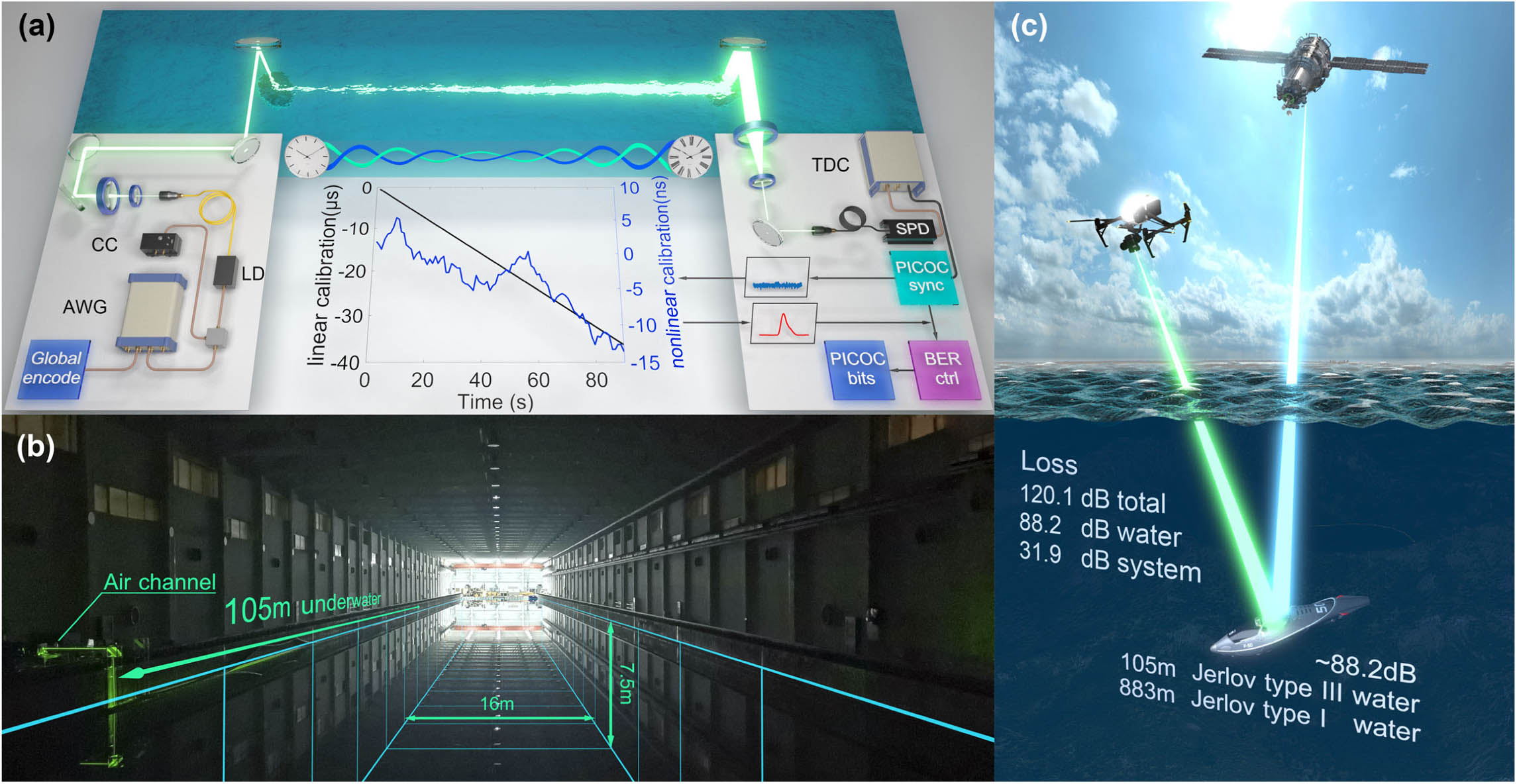
    Fig. 1. PICOC systems for underwater optical communication. (a) The global encoding module transforms the original message into redundant bits globally distributed in time. An arbitrary waveform generator (AWG) converts redundant bits to electric pulses using the return-to-zero on–off keying modulation. The electric pulse sequence is combined with a constant current (CC) signal by a bias-tee, directly driving the 520 nm laser diode (LD). The laser beam goes through the air channel and is guided into the underwater channel using a pair of steering mirrors. In the receiving terminal, surviving photons are coupled into a multimode fiber by a telescope system and sent into a single-photon detector (SPD). A time-to-digital converter (TDC) records the arrival time of the single-photon stream with a high time resolution and transmits the data stream into three process modules. The first process module analyzes the internal time correlation shared among the received photons and retrieves the high-precision time frame. The second process module predicts and manipulates the bit error rate (BER) to the desired value utilizing the time evolution of photon statistics. The last process module decodes the processed data into message bits, realizing the underwater data extraction from the sparse single-photon stream. (b) Photograph of the experimental site. The dimension of the towing tank is 300 m long, 16 m wide, and 7.5 m deep. Both the transmitting and receiving terminals are located on the long side of the towing tank. (c) The underwater photon-inter-correlation optical communication is expected to establish the air–water optical communication link. The demonstrated distance is 105-m-long in Jerlov type III coastal water, equivalent to the channel loss of 883-m-long Jerlov type I clean water.
    Establishing reliable underwater optical communication links using time-evolving photon statistics. (a) Time evolution of the BER with different signal-to-noise ratio (SNR) conditions. We show the theoretical, analytical, and experimental results of 100-m-long underwater optical communication. (b) The retrieved waveform with and without the PICOC synchronization scheme. We show the experimental results of 100-m-long underwater transmission distance and −1.26 dB SNR. (c) Time evolution of photon statistics with 100-m-long underwater transmission distance and −1.26 dB SNR. The light blue surface represents the expected photon statistics, and dark blue curves show the experimental results. (d) Time evolution of photon statistics with 100-m-long underwater transmission distance and 12.14 dB SNR. FEC, forward error correction.
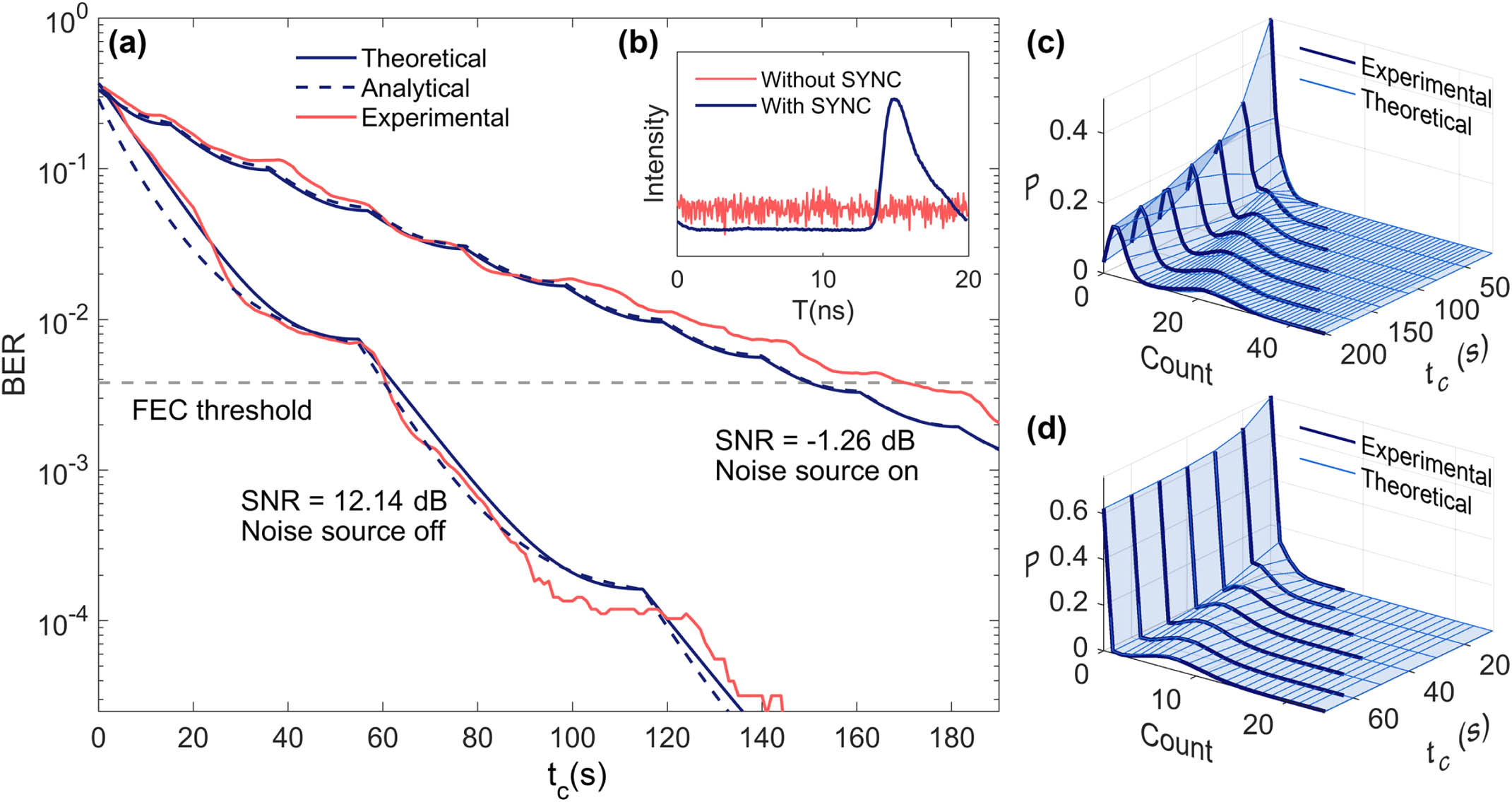
    Fig. 2. Establishing reliable underwater optical communication links using time-evolving photon statistics. (a) Time evolution of the BER with different signal-to-noise ratio (SNR) conditions. We show the theoretical, analytical, and experimental results of 100-m-long underwater optical communication. (b) The retrieved waveform with and without the PICOC synchronization scheme. We show the experimental results of 100-m-long underwater transmission distance and 1.26  dB SNR. (c) Time evolution of photon statistics with 100-m-long underwater transmission distance and 1.26  dB SNR. The light blue surface represents the expected photon statistics, and dark blue curves show the experimental results. (d) Time evolution of photon statistics with 100-m-long underwater transmission distance and 12.14 dB SNR. FEC, forward error correction.
    Experimental BER and correlation gain manipulation for underwater optical communication. (a) Measured BER as a function of correlation time with 100-m-long underwater transmission distance. The received signal intensity is around 4000 photons per second. We switch off all lights inside the towing tank to obtain a low-noise environment. Noise photons contributed by the detector and the low-noise environment are around 50 photons per second. By turning on the lights inside the facility, we gradually level up the background noise. About 2000 noise photons per second are received under the high-noise environment. The ultrahigh-noise environment is achieved by opening all lights on, obtaining a noise level of 5700 photons per second. Light-colored curves and dark-colored curves represent the theoretical expectation and experimental results, respectively. (b) Measured BER as a function of correlation time with 105-m-long underwater transmission distance and low-noise environment. The received signal intensity is around 1500 photons per second, with only 8×10⁻⁵ photon survives in each pulse. (c) Optimal strategy for underwater optical communication. We show the theoretical, analytical, and experimental time evolution of correlation gain.
    Fig. 3. Experimental BER and correlation gain manipulation for underwater optical communication. (a) Measured BER as a function of correlation time with 100-m-long underwater transmission distance. The received signal intensity is around 4000 photons per second. We switch off all lights inside the towing tank to obtain a low-noise environment. Noise photons contributed by the detector and the low-noise environment are around 50 photons per second. By turning on the lights inside the facility, we gradually level up the background noise. About 2000 noise photons per second are received under the high-noise environment. The ultrahigh-noise environment is achieved by opening all lights on, obtaining a noise level of 5700 photons per second. Light-colored curves and dark-colored curves represent the theoretical expectation and experimental results, respectively. (b) Measured BER as a function of correlation time with 105-m-long underwater transmission distance and low-noise environment. The received signal intensity is around 1500 photons per second, with only 8×10⁵ photon survives in each pulse. (c) Optimal strategy for underwater optical communication. We show the theoretical, analytical, and experimental time evolution of correlation gain.
    Long-term system stability of underwater PICOC. (a) The experimental long-term BER performance and the corresponding SNR condition of 100-m-long low-noise underwater optical communication. (b) Experimental BER stability of 105-m-long underwater optical communication in one hour. (c) The SNR condition decreases with the increase of noise. The system remains the robustness in obtaining the desired BER during the one-hour measurement. (d) With the increase of noise, the SNR condition inevitably drops below 0 dB. However, the system can still push the BER below the FEC threshold and establish reliable underwater communication links in the long term. (e) The demonstrated long-term BER stability of the system with various BER levels, noise levels, and underwater transmission distance. The red plus sign indicates the BER value away from the median.
    Fig. 4. Long-term system stability of underwater PICOC. (a) The experimental long-term BER performance and the corresponding SNR condition of 100-m-long low-noise underwater optical communication. (b) Experimental BER stability of 105-m-long underwater optical communication in one hour. (c) The SNR condition decreases with the increase of noise. The system remains the robustness in obtaining the desired BER during the one-hour measurement. (d) With the increase of noise, the SNR condition inevitably drops below 0 dB. However, the system can still push the BER below the FEC threshold and establish reliable underwater communication links in the long term. (e) The demonstrated long-term BER stability of the system with various BER levels, noise levels, and underwater transmission distance. The red plus sign indicates the BER value away from the median.
    Enhanced glass for ultraweak light observation. (a) The homemade enhanced glass is specialized in assisting the ultraweak light searching. Two high-sensitivity image sensors provide the enhanced binocular vision. The vision signal is then transmitted to the computer through the cable. Next, the computer converts the vision signal into a 3D video stream that the brain can interpret. Finally, we monitor the video stream through a 3D head-mounted display and obtain real-time enhanced vision. The high-storage battery provides the battery lift of the enhanced glass that lasts for an hour. (b) Enhanced vision of the left sensor. The vision of the right sensor is similar to the left sensor but with a different visual angle. (c) Vision of the naked eye. The beacon light is barely visible.
    Fig. 5. Enhanced glass for ultraweak light observation. (a) The homemade enhanced glass is specialized in assisting the ultraweak light searching. Two high-sensitivity image sensors provide the enhanced binocular vision. The vision signal is then transmitted to the computer through the cable. Next, the computer converts the vision signal into a 3D video stream that the brain can interpret. Finally, we monitor the video stream through a 3D head-mounted display and obtain real-time enhanced vision. The high-storage battery provides the battery lift of the enhanced glass that lasts for an hour. (b) Enhanced vision of the left sensor. The vision of the right sensor is similar to the left sensor but with a different visual angle. (c) Vision of the naked eye. The beacon light is barely visible.
    Light SourceaPowerModulationbDetectorcDistance/LossSNRReceived Photons in Each PulseReferences
    450 nm LD51.3 mWNRZ-OOKPD20 m/34.3 dB+3.8  dB104[7]
    520 nm LD19.4 mWNRZ-OOKPD34.5 m/21.1 dB+1.8  dB105[8]
    532 nm SSL1 mJ at 1.5 kHzPPMSPD120 m/136.8 dB+2.5  dB100[12]
    450 nm LD174 μWPPMMPPC46 m/31.6 dB+2.1  dB104[10]
    520 nm LD7.3 mWNRZ-OOKPD100 m/28.4 dB+2.6  dB105[11]
    520 nm LD592 μWRZ-OOKSPD105 m/120.1 dB−2.3 dB105This work
    Table 1. Comparison of Underwater Optical Communication Systems
    Zeng-Quan Yan, Cheng-Qiu Hu, Zhan-Ming Li, Zhong-Yuan Li, Hang Zheng, Xian-Min Jin. Underwater photon-inter-correlation optical communication[J]. Photonics Research, 2021, 9(12): 2360
    Download Citation