
Zeng-Quan Yan, Cheng-Qiu Hu, Zhan-Ming Li, Zhong-Yuan Li, Hang Zheng, Xian-Min Jin. Underwater photon-inter-correlation optical communication[J]. Photonics Research, 2021, 9(12): 2360
- Photonics Research
- Vol. 9, Issue 12, 2360 (2021)
Abstract
1. INTRODUCTION
Ocean, covering over 70% of Earth’s surface, is one of the most valuable sources of natural materials such as minerals, oils, foods, and renewable energy. The development of modern technology extends human’s available resources beyond the shallow sea and into the deep sea, which presents an urgent need for high-capacity, long-distance underwater wireless communication. Underwater wireless communication using acoustic waves as carriers has a long transmission distance, but the low channel capacity limits the maximum data rate for underwater acoustic communication [1,2]. More importantly, the propagation of underwater acoustic carriers is localized in the water medium, restricting the flexible air–water cross-medium communication between underwater vehicles and satellites.
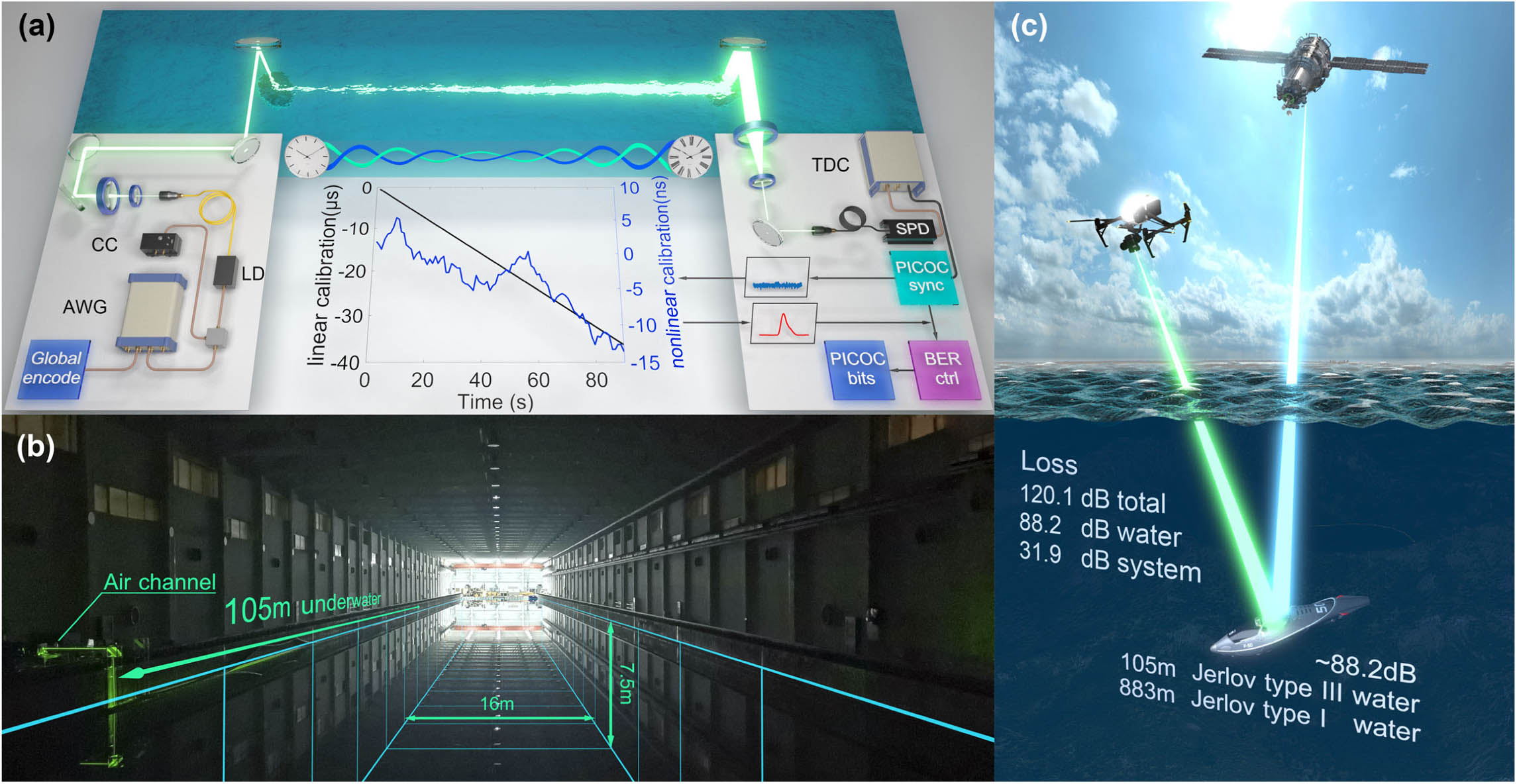
Figure 1.PICOC systems for underwater optical communication. (a) The global encoding module transforms the original message into redundant bits globally distributed in time. An arbitrary waveform generator (AWG) converts redundant bits to electric pulses using the return-to-zero on–off keying modulation. The electric pulse sequence is combined with a constant current (CC) signal by a bias-tee, directly driving the 520 nm laser diode (LD). The laser beam goes through the air channel and is guided into the underwater channel using a pair of steering mirrors. In the receiving terminal, surviving photons are coupled into a multimode fiber by a telescope system and sent into a single-photon detector (SPD). A time-to-digital converter (TDC) records the arrival time of the single-photon stream with a high time resolution and transmits the data stream into three process modules. The first process module analyzes the internal time correlation shared among the received photons and retrieves the high-precision time frame. The second process module predicts and manipulates the bit error rate (BER) to the desired value utilizing the time evolution of photon statistics. The last process module decodes the processed data into message bits, realizing the underwater data extraction from the sparse single-photon stream. (b) Photograph of the experimental site. The dimension of the towing tank is 300 m long, 16 m wide, and 7.5 m deep. Both the transmitting and receiving terminals are located on the long side of the towing tank. (c) The underwater photon-inter-correlation optical communication is expected to establish the air–water optical communication link. The demonstrated distance is 105-m-long in Jerlov type III coastal water, equivalent to the channel loss of 883-m-long Jerlov type I clean water.
Signal-to-noise ratio (SNR) is another comprehensive benchmark related to signal intensity, environmental noise, detectors’ dark count, detection schemes, and channel loss. SNR higher than 0 dB indicates more signal than noise, which contributes to obtaining a lower communication error rate. When the signal inevitably drops below the noise level due to the huge underwater channel loss, the error rate goes too high to establish reliable underwater optical communication links. Coherent detection [13,14], with an outstanding noise suppression ability, has been widely used in free-space optical communication [15,16]. However, harsh environments of long-distance underwater free space restrict the application of coherent optical systems. Innovative research has applied single-photon detectors (SPDs) to improve the system sensitivity against low SNR and huge underwater channel loss, directly utilizing the detector’s photon-counting feature [10,12].
Here, we treat light as a stream of photons from the perspective of quantum optics. In underwater scenarios, each photon in the stream can carry many degrees of freedom, such as time, polarization [17–20], and orbital angular momentum [21,22]. By correlating many more photons globally, we can extract much more implicit information and obtain the time-evolving photon statistics. We experimentally demonstrate the photon-inter-correlation optical communication (PICOC) in air–water scenarios using a microwatt laser (see Fig. 1). We establish long-distance underwater optical communication links against high loss, negative SNR, and water disturbance by retrieving the internal time information shared in the sparse single-photon stream globally. Furthermore, the time evolution of photon statistics reveals the condition of the underwater channel, enabling the precise manipulation of the underwater communication performance on demand.
Sign up for Photonics Research TOC. Get the latest issue of Photonics Research delivered right to you!Sign up now
2. TIME FRAME RETRIEVAL OF THE SPARSE SINGLE-PHOTON STREAM
Sharing the time frame between remote users is the foundation of communication. However, time and frequency differences between remote clocks are inevitably affected by voltage fluctuation, temperature drift, and the Doppler shift [23]. Even using atomic clocks with outstanding frequency stability [24], the ticking rate difference caused by the time dilation effect of relative motion contributes to the major clock drift in satellite-underwater optical communication [25–27].
With excellent ability against loss and noise, pulse lasers have become the mainstream solution to construct the time frame between remote underwater clocks. Underwater optical communication using photodiodes as detectors requires hundreds of thousands of photons per pulse to establish a reliable time frame [11]. By introducing SPDs as detectors, underwater optical communication systems can build the time frame against higher underwater channel loss, requiring only a few photons per pulse [12]. However, no matter whether we use photodiodes or SPDs to detect light pulses, we always try to retrieve many photons in each pulse, which heavily depends on the pulse energy of laser sources. Once the underwater channel loss further increases, the required pulse energy would reach the limits of existing technology.
Instead of collecting many photons in each pulse, we propose a global correlation method to establish the time frame between remote underwater clocks, pushing the required photon number 4 orders of magnitude down. In our underwater experiment, the received signal intensity is weak. Only about photon survives in each pulse. The single-photon stream is so sparse that only about one signal photon is located in tens of thousands of pulses. By introducing the PICOC scheme, we can still retrieve the time frame from the surviving photons in millions of pulses. The concrete proposals and technical details of PICOC are announced in Ref. [28]. The core concept is to utilize the time interval in which photons are expected to arrive. We use photons as carriers for both time frames and bit messages. By recording the arrival time of photons and analyzing the internal time correlation shared among the sparse single-photon stream globally, we share the time frame between remote underwater clocks with high accuracy. According to the retrieved time frame, we draw all photons into a pulse period and obtain the pulse waveform [see Fig. 2(b)]. The time frame is well established compared to the result without our scheme.
![]()
Figure 2.Establishing reliable underwater optical communication links using time-evolving photon statistics. (a) Time evolution of the BER with different signal-to-noise ratio (SNR) conditions. We show the theoretical, analytical, and experimental results of 100-m-long underwater optical communication. (b) The retrieved waveform with and without the PICOC synchronization scheme. We show the experimental results of 100-m-long underwater transmission distance and
3. TIME EVOLUTION OF PHOTON STATISTICS
We use the time evolution of photon statistics to distinguish signal from noise, enabling the manipulation of communication performance against huge underwater channel loss and extreme SNR conditions. At the transmitting terminal, we represent messages as redundant pulses globally distributed in the time domain. Based on the retrieved time frame, we can precisely locate the pulse position of surviving photons. By further correlating photons located in the corresponding pulse position, we cluster redundant photons coding the specific bit. The correlated photon number of message bits forms the photon statistics. Generally, the photon number distribution of these bits is bimodal: 0-bits in the message contribute to the left peak, and 1-bits contribute to the right [see Fig. 2(d)]. By analyzing data for a longer time, we can correlate many more photons and obtain a different distribution pattern.
The time evolution of photon statistics has a similarity with ripples on the water. In the beginning, 0-bit distribution and 1-bit distribution are too close to set a threshold dividing signal from noise. With time evolving, more photons are thrown into the message pool, pushing the photon statistics away from the initial position. Meanwhile, the dynamic behavior of photon statistics separates these distributions progressively at a constant rate, creating the opportunity to retrieve message bits with a lower bit error rate (BER) [see Figs. 2(c) and 2(d)]. In other words, different correlation time characterizes different photon statistics patterns, which consequently maps different BER. Eventually, these two distributions separate far enough to establish a reliable underwater optical communication link.
The photon internal time correlation feature and the global encoding feature guarantee that the dynamic behavior of photon statistics is only driven by the measured time, realizing the precise manipulation of BER. Once the received photons are inadequate for retrieving the message with the desired BER, we just need to extend the measured time, correlate more photons, and repeat until achieving success.
4. QUANTIFICATION OF TIME-EVOLVING PARAMETERS
The light decays into weak coherent-state signals through the high-loss underwater channel [29,30]. The received photon number in each pulse follows a Poisson distribution. Noise, no matter from the detector’s dark count or stray light, also follows the Poisson distribution [31]. The bit error rate of underwater PICOC can be expressed as [28]
In Fig. 2(a), the experimental error probability shows the periodic oscillation over time, which is consistent with the theoretical expectation. The periodic oscillation indicates that the declining rate of BER varies all the time. Here, we define the correlation gain as the derivative of error probability with respect to time. By manipulating the value of , we can maximize the time efficiency and obtain the optimal BER enhancement. However, directly deriving from Eq. (1) is difficult (see Appendix A for further details). Therefore, we transform the BER into an approximate expression divided into two physical pictures
The approximate expression consists of two terms, the consecutive term and the oscillating term. Here, represents the coarse correlation gain. and indicate the phase and intercept. denotes the intensity of the oscillation. and characterize the oscillating period and initial phase. The consecutive term treats light as a continuous field, which determines the global time-evolving tendency of BER. Dominant factors such as coarse correlation gain , phase , and intercept contribute to obtaining a smooth BER variation with time. When we treat light as a stream of photons from the picture of quantum optics, we can observe the oscillating term revealing the fine structure of BER’s time evolution. Each oscillation cycle characterizes a value switch of the optimal photon number threshold retrieving messages with the lowest error probability. We can derive the single-photon-related oscillation period , amplitude , and initial phase from the expression of (see Appendix A for further details). The approximate expression of BER provides a low computational complexity way to predict the required correlation time, realizing the precise manipulation of underwater optical communication performance on demand. Then, we derive the expression of correlation gain from Eq. (2):
The overall correlation gain also consists of two terms, the consecutive term contributed by the coarse correlation gain and the oscillating term contributed by the fine correlation gain. The higher the value of , the lower the BER obtained within a given time interval. When the value of periodically drops to zero, the time evolution of BER becomes irrelevant with correlation time. Therefore, we should try to avoid these low gain regions, achieving the optimal time efficiency of the underwater optical communication system.
5. EXPERIMENT AND RESULTS
In the transmitting terminal, a global encoding module transforms the 125-kbit message into globally redundant bits by repeating the entire message cyclically. Redundant bits are then converted to 50 MHz (5 ns pulse width) electric pulse sequences using an arbitrary waveform generator (Zurich Instruments, HDAWG, 750 MHz bandwidth). Empty pulses represent 0-bits and non-zero pulses represent 1-bits. After that, we drive the 520 nm green laser diode using a bias-tee combining pulse sequences with the constant current signal generated by a Thorlabs KLD101 laser driver [see Fig. 1(a)]. The global encoding feature allows us to distribute errors evenly into all bits and prevent the localized high BER caused by water disturbance.
After transmitting through the air channel, we use a pair of steering mirrors to guide the signal through the air–water interface and into the towing tank [see Figs. 1(a) and 1(b)]. The towing tank is a test facility for the research of dynamic performances of ships and underwater vehicles, providing a perfect site for our long-distance underwater experiments. Water clarity is a dominant factor for underwater optical communication and can be quantified by Jerlov water type. For the 520 nm wavelength, the channel attenuations of Jerlov type I, type II, and type III water are 0.22, 0.30, and 0.51 dB/m, respectively [3]. Generally, Jerlov type I water only exists in the deep ocean, while Jerlov type II water is commonly seen in shallow water away from the shore. In our experiment, water in the tank has been used for testing various underwater vehicles. The light attenuation of the water is around 0.84 dB/m for the 520 nm wavelength, which is as turbid as the Jerlov type III (3C) coastal water [3].
In the receiving terminal, we guide the signal out of the water using two steering mirrors. The decoding setup includes a pair of lenses, a coupler module, an SPD, a time-to-digital converter, and three process modules [see Fig. 1(a)]. We choose an SPD from Excelitas SPCM CD3724H, a special model of SPCM-AQRH-14 series device optimized for the green light detection, with a detection efficiency of 47% at 520 nm wavelength. The Siminics FT1080 time-to-digital converter keeps recording the arrival time of the photon stream with a time resolution of 64 ps. The first process module utilizes the global time correlation to retrieve the time frame shared in the sparse single-photon stream. By characterizing the linear and nonlinear clock drift between remote underwater clocks, we manage to synchronize the signal within 1 ns, close to the timing jitter of the SPD [see Fig. 1(a)]. The calibrated arrival time information is then sent into the second process module for BER manipulation. In this stage, we identify the pulse position of each photon first. The pulse position of a photon can be expressed as , where represents the calibrated arrival time and represents the 20 ns pulse period. Then we retrieve the corresponding bit position of a photon, which can be expressed as ( represents the message length). The retrieval of bit position allows us to cluster redundant photons coding a specific bit and count the correlated photon number. By correlating all photons in the sparse single-photon stream, we can obtain the time evolution of photon statistics and manipulate the BER performance. In the last process module, we decode the correlated photon number back into a binary form by choosing the optimal photon number threshold . For instance, when the correlated photon number is larger than , we define it as a 1-bit and vice versa.
We experimentally demonstrate the 105-m-long underwater optical communication in the towing tank. Despite the huge underwater channel loss, we can still achieve the single-channel data rate ranging from 430 bits per second (bps) to 2 kbps. In Fig. 3, we illustrate the time-evolving behavior of BER under various underwater distances and noise levels. Noise here plays a similar role to water attenuation in decreasing the SNR, which can be overcome by correlating more photons [see Fig. 3(a)]. Considering the 31.9 dB system loss, we build the high-fidelity underwater optical communication links against a total loss up to 120.1 dB using only a 592 μW laser diode. The loss contributed by water is 88.2 dB, which is equivalent to the loss of 883-m-long Jerlov type I water, extending the low power consumption underwater optical communication to a new realm.
![]()
Figure 3.Experimental BER and correlation gain manipulation for underwater optical communication. (a) Measured BER as a function of correlation time with 100-m-long underwater transmission distance. The received signal intensity is around 4000 photons per second. We switch off all lights inside the towing tank to obtain a low-noise environment. Noise photons contributed by the detector and the low-noise environment are around 50 photons per second. By turning on the lights inside the facility, we gradually level up the background noise. About 2000 noise photons per second are received under the high-noise environment. The ultrahigh-noise environment is achieved by opening all lights on, obtaining a noise level of 5700 photons per second. Light-colored curves and dark-colored curves represent the theoretical expectation and experimental results, respectively. (b) Measured BER as a function of correlation time with 105-m-long underwater transmission distance and low-noise environment. The received signal intensity is around 1500 photons per second, with only
In Fig. 3(b), we show the theoretical and experimental BER results of the 105-m-long Jerlov type III (3C) underwater experiment. The experimental time evolution of BER is consistent with the theoretical expectation, realizing the precise manipulation of underwater optical communication performance. By manipulating the correlation gain , we can further maximize the time efficiency of the underwater PICOC system. Figure 3(c) shows the time evolution of correlation gain from the results of the 105-m-long underwater experiment. The analytical agrees well with the theoretical results, providing a fast and low-computational-complexity way to predict and manipulate the optimal correlation time. Both the theoretical and experimental correlation gain gives the periodic time-evolving feature. Here, every oscillation cycle represents a value switch of the optimal photon number threshold . The area bounded by the curve and the coordinate axes characterize the BER enhancement contributed by time correlation. Generally, when has just gone through a round of value switching, the correlation gain reaches the high gain point. However, the short integration time causes the small integral, restricting the BER enhancement to the idle region. When the value of is close to the next round switch, the correlation gain drops too low to enhance the BER performance by expanding the correlation time. Therefore, we should manipulate the value of at the mid-gain point to achieve the optimal strategy.
The semi-open towing tank, whose ambient condition is very similar to the open space in the ocean, gives us the opportunity to show the robustness of our scheme against underwater turbulence, air–water interface fluctuation, and impurities interference in water. In Fig. 4, we check the long-term stability of underwater PICOC against various underwater distance and noise levels. As the noise increases, the SNR gradually decreases and inevitably drops below 0 dB, where more noise photons are received than signal photons [see Figs. 4(a)–4(d)]. Despite the diverse SNR condition, underwater turbulence, and other interference, we can still push the BER to the desired region and maintain long-term stability. By manipulating the desired BER at different BER levels, we obtain error bars shown in Fig. 4(e). Underwater optical communication links are well established by correlating the internal time information shared among the sparse single-photon stream.
![]()
Figure 4.Long-term system stability of underwater PICOC. (a) The experimental long-term BER performance and the corresponding SNR condition of 100-m-long low-noise underwater optical communication. (b) Experimental BER stability of 105-m-long underwater optical communication in one hour. (c) The SNR condition decreases with the increase of noise. The system remains the robustness in obtaining the desired BER during the one-hour measurement. (d) With the increase of noise, the SNR condition inevitably drops below 0 dB. However, the system can still push the BER below the FEC threshold and establish reliable underwater communication links in the long term. (e) The demonstrated long-term BER stability of the system with various BER levels, noise levels, and underwater transmission distance. The red plus sign indicates the BER value away from the median.
6. DISCUSSION AND OUTLOOK
In summary, the air–water transmission feature of light endows us the possibility to establish cross-medium links between satellites and underwater vehicles. We experimentally test the long-distance underwater optical communication in the semi-open underwater environment, demonstrating the key process of air–water optical communication. By harnessing the single-photon feature and internal correlation of light, we show our system’s capability against the 105-m-long underwater channel and a total loss up to 120.1 dB. We also show that the communication robustness is strong even against underwater turbulence and air–water interface fluctuation by separating a single-photon signal embedded in a noise 2 times higher. The global encoding feature and time-evolving photon statistics allow us to retrieve the implicit correlation shared among the sparse single-photon stream with high fidelity, realizing the precise BER manipulation of the underwater optical communication on demand. The demonstrated underwater channel loss is equivalent to 883-m-long (at 450 nm wavelength) and 398-m-long (at 520 nm wavelength) Jerlov type I water, inspiring the practical air–water optical communication a leap forward.
The high loss tolerance of underwater PICOC gives us the power to explore various air–water applications. By purposely enlarging the beam divergence and increasing the geometric loss, we can establish air–water optical communication links without accurately targeting underwater vehicles. The air–water photonic broadcast is another exciting application. We can further expand the beam to a wide-area coverage and give instructions to swathes of underwater terminals. It would also be promising to introduce our scheme in air–water time and frequency transmission, enabling the autonomous positioning of underwater vehicles below the safety depth. Constructing the underwater single-photon detection network is also achievable. By correlating photons received by remote time-independent underwater detectors, we may bring the trigger-free underwater detection network into real life [32,33].
Acknowledgment
Acknowledgment. X.-M. J. acknowledges additional support from the Shanghai Talent Program and support from Zhiyuan Innovative Research Center of Shanghai Jiao Tong University.
APPENDIX A: CAPTURE OF THE SPARSE SINGLE-PHOTON STREAM
The capture of the sparse single-photon stream through the long-distance underwater channel is very challenging. The signal intensity drops to around 1500 photons per second at the receiving terminal, invisible to the naked eye. Here, we use a 532 nm high-peak-power laser as the beacon light. By combining the 520 nm signal light and the 532 nm beacon light using a dichroic mirror, we guarantee that the spatial modes of signal and beacon overlap within the 300-m-long free space. After the huge underwater channel loss, only the beacon light is visible. Once we optimize the coupling efficiency of the beacon light, the capture of the signal light is also well established. By setting several key distances, such as 20, 30, 40, 60, 100, and 105 m, we gradually realize the signal capture through a longer underwater transmission distance. Notably, at the underwater transmission distance beyond 100 m, the beacon light becomes barely visible, increasing the difficulty in capturing the beacon light and the signal light. Here, we use a homemade visual enhancement device to obtain a real-time 3D enhanced vision [see Fig.
![]()
Figure 5.Enhanced glass for ultraweak light observation. (a) The homemade enhanced glass is specialized in assisting the ultraweak light searching. Two high-sensitivity image sensors provide the enhanced binocular vision. The vision signal is then transmitted to the computer through the cable. Next, the computer converts the vision signal into a 3D video stream that the brain can interpret. Finally, we monitor the video stream through a 3D head-mounted display and obtain real-time enhanced vision. The high-storage battery provides the battery lift of the enhanced glass that lasts for an hour. (b) Enhanced vision of the left sensor. The vision of the right sensor is similar to the left sensor but with a different visual angle. (c) Vision of the naked eye. The beacon light is barely visible.
APPENDIX B: DERIVATION OF THE BIT ERROR RATE IN AN UNDERWATER PICOC SYSTEM
The received photon number in each pulse follows a Poisson distribution with a parameter [
In long-distance underwater optical communication, the channel loss is extremely large. The received photon number in a single pulse is around photon per pulse. The probability of receiving the multiple-photon state is extremely low. The detected photon statistics of a signal pulse follows a Poisson distribution with a parameter :
By correlating redundant pulses coding a specific bit, we can obtain the signal photon statistics expressed as
The expression of is a step function, contributing the oscillatory time evolution of BER. By deriving the characteristic of the step function, we obtain the oscillation period and initial phase of the time evolution of BER:
Approximately, the BER of PICOC can be expressed as
APPENDIX C: EVALUATION OF THE SNR FROM THE EYE DIAGRAM
In Refs. [
References
[1] I. F. Akyildiz, D. Pompili, T. Melodia. Challenges for efficient communication in underwater acoustic sensor networks. ACM SIGBED Rev., 1, 3-8(2004).
[2] M. Stojanovic, J. Preisig. Underwater acoustic communication channels: propagation models and statistical characterization. IEEE Commun. Mag., 47, 84-89(2009).
[3] M. G. Solonenko, C. D. Mobley. Inherent optical properties of Jerlov water types. Appl. Opt., 54, 5392-5401(2015).
[4] C. Wang, H.-Y. Yu, Y.-J. Zhu. A long distance underwater visible light communication system with single photon avalanche diode. IEEE Photon. J., 8, 7906311(2016).
[5] M. Doniec, C. Detweiler, I. Vasilescu, M. Chitre, M. Hoffmann-Kuhnt, D. Rus. Aquaoptical: a lightweight device for high-rate long-range underwater point-to-point communication. Mar. Technol. Soc. J., 44, 55-65(2010).
[6] M. Doniec, D. Rus. Bidirectional optical communication with aquaoptical II. IEEE International Conference on Communication Systems, 390-394(2010).
[7] C. Shen, Y. Guo, H. M. Oubei, T. K. Ng, G. Liu, K.-H. Park, K.-T. Ho, M.-S. Alouini, B. S. Ooi. 20-meter underwater wireless optical communication link with 1.5 Gbps data rate. Opt. Express, 24, 25502-25509(2016).
[8] X. Liu, S. Yi, X. Zhou, Z. Fang, Z.-J. Qiu, L. Hu, C. Cong, L. Zheng, R. Liu, P. Tian. 34.5 m underwater optical wireless communication with 2.70 Gbps data rate based on a green laser diode with NRZ-OOK modulation. Opt. Express, 25, 27937-27947(2017).
[9] P. Tian, X. Liu, S. Yi, Y. Huang, S. Zhang, X. Zhou, L. Hu, L. Zheng, R. Liu. High-speed underwater optical wireless communication using a blue GaN-based micro-LED. Opt. Express, 25, 1193-1201(2017).
[10] J. Shen, J. Wang, X. Chen, C. Zhang, M. Kong, Z. Tong, J. Xu. Towards power-efficient long-reach underwater wireless optical communication using a multi-pixel photon counter. Opt. Express, 26, 23565-23571(2018).
[11] J. Wang, C. Lu, S. Li, Z. Xu. 100 m/500 Mbps underwater optical wireless communication using an NRZ-OOK modulated 520 nm laser diode. Opt. Express, 27, 12171-12181(2019).
[12] S. Hu, L. Mi, T. Zhou, W. Chen. 35.88 attenuation lengths and 3.32 bits/photon underwater optical wireless communication based on photon-counting receiver with 256-ppm. Opt. Express, 26, 21685-21699(2018).
[13] H. P. Yuen, V. W. Chan. Noise in homodyne and heterodyne detection. Opt. Lett., 8, 177-179(1983).
[14] G. Abbas, V. Chan, T. Yee. Local-oscillator excess-noise suppression for homodyne and heterodyne detection. Opt. Lett., 8, 419-421(1983).
[15] R. Fields, D. Kozlowski, H. Yura, R. Wong, J. Wicker, C. Lunde, M. Gregory, B. Wandernoth, F. Heine. 5.625 Gbps bidirectional laser communications measurements between the NFIRE satellite and an optical ground station. International Conference on Space Optical Systems and Applications (ICSOS), 44-53(2011).
[16] W. Chen, J. Sun, X. Hou, R. Zhu, P. Hou, Y. Yang, M. Gao, L. Lei, K. Xie, M. Huang, R. Li, H. Zang, Y. Wan, E. Dai, Y. Xi, W. Lu, S. Wei, L. Liu, J. Li. 5.12 Gbps optical communication link between LEO satellite and ground station. IEEE International Conference on Space Optical Systems and Applications (ICSOS), 260-263(2017).
[17] L. Ji, J. Gao, A.-L. Yang, Z. Feng, X.-F. Lin, Z.-G. Li, X.-M. Jin. Towards quantum communications in free-space seawater. Opt. Express, 25, 19795-19806(2017).
[18] C.-Q. Hu, Z.-Q. Yan, J. Gao, Z.-Q. Jiao, Z.-M. Li, W.-G. Shen, Y. Chen, R.-J. Ren, L.-F. Qiao, A.-L. Yang, H. Tang, X.-M. Jin. Transmission of photonic polarization states through 55-m water: towards air-to-sea quantum communication. Photon. Res., 7, A40-A44(2019).
[19] C.-Q. Hu, Z.-Q. Yan, J. Gao, Z.-M. Li, H. Zhou, J.-P. Dou, X.-M. Jin. Decoy-state quantum key distribution over a long-distance high-loss air-water channel. Phys. Rev. Appl., 15, 024060(2021).
[20] Z. Feng, S. Li, Z. Xu. Experimental underwater quantum key distribution. Opt. Express, 29, 8725-8736(2021).
[21] Y. Chen, W.-G. Shen, Z.-M. Li, C.-Q. Hu, Z.-Q. Yan, Z.-Q. Jiao, J. Gao, M.-M. Cao, K. Sun, X.-M. Jin. Underwater transmission of high-dimensional twisted photons over 55 meters. PhotoniX, 1, 5(2020).
[22] F. Hufnagel, A. Sit, F. Bouchard, Y. Zhang, D. England, K. Heshami, B. J. Sussman, E. Karimi. Investigation of underwater quantum channels in a 30 meter flume tank using structured photons. New J. Phys., 22, 093074(2020).
[23] H. Takenaka, A. Carrasco-Casado, M. Fujiwara, M. Kitamura, M. Sasaki, M. Toyoshima. Satellite-to-ground quantum-limited communication using a 50-kg-class microsatellite. Nat. Photonics, 11, 502-508(2017).
[24] Z. L. Newman, V. Maurice, T. Drake, J. R. Stone, T. C. Briles, D. T. Spencer, C. Fredrick, Q. Li, D. Westly, B. R. Ilic, B. Shen, M.-G. Suh, K. Y. Yang, C. Johnson, D. M. S. Johnson, L. Hollberg, K. J. Vahala, K. Srinivasan, S. A. Diddams, J. Kitching, S. B. Papp, M. T. Hummon. Architecture for the photonic integration of an optical atomic clock. Optica, 6, 680-685(2019).
[25] N. Ashby. Relativity in the global positioning system. Living Rev. Relativity, 6, 1(2003).
[26] L. Cacciapuoti, C. Salomon. Space clocks and fundamental tests: the ACES experiment. Eur. Phys. J. Spec. Top., 172, 57-68(2009).
[27] H. Müller, A. Peters, S. Chu. A precision measurement of the gravitational redshift by the interference of matter waves. Nature, 463, 926-929(2010).
[28] Z.-Q. Yan, C.-Q. Hu, Z.-M. Li, Z.-Y. Li, H. Zheng, X.-M. Jin. Photon-inter-correlation optical communication(2021).
[29] X. Ma, B. Qi, Y. Zhao, H.-K. Lo. Practical decoy state for quantum key distribution. Phys. Rev. A, 72, 012326(2005).
[30] H.-K. Lo, X. Ma, K. Chen. Decoy state quantum key distribution. Phys. Rev. Lett., 94, 230504(2005).
[31] R. G. Gallager. Stochastic Processes: Theory for Applications(2013).
[32] A. Maccarone, A. McCarthy, X. Ren, R. E. Warburton, A. M. Wallace, J. Moffat, Y. Petillot, G. S. Buller. Underwater depth imaging using time-correlated single-photon counting. Opt. Express, 23, 33911-33926(2015).
[33] A. Maccarone, F. M. D. Rocca, A. McCarthy, R. Henderson, G. S. Buller. Three-dimensional imaging of stationary and moving targets in turbid underwater environments using a single-photon detector array. Opt. Express, 27, 28437-28456(2019).

Set citation alerts for the article
Please enter your email address
© Copyright 2018-2021 | Chinese Laser Press. All Rights Reserved 沪ICP备15018463号-20