
Hafiz Saad Khaliq, Inki Kim, Aima Zahid, Joohoon Kim, Taejun Lee, Trevon Badloe, Yeseul Kim, Muhammad Zubair, Kashif Riaz, Muhammad Qasim Mehmood, Junsuk Rho. Giant chiro-optical responses in multipolar-resonances-based single-layer dielectric metasurfaces[J]. Photonics Research, 2021, 9(9): 1667
- Photonics Research
- Vol. 9, Issue 9, 1667 (2021)
Abstract
1. INTRODUCTION
Artificially engineered chiral nanostructures have gained attention due to advancements in fabrication techniques, their exceptional ability to control electromagnetic (EM) waves, and efficiencies that can surpass natural materials [1–12]. These developments led to the investigation of chiral metamaterials and metasurfaces as ultrathin circular polarizers [2] and chiral sensors [4]. Additionally, chiro-optical effects have been demonstrated in three-dimensional (3D), multilayer, and planar structures. Although 3D chiral metamaterials [2,13–15] and multilayer structures [16–20] have shown remarkable abilities to tailor chiro-optical effects, two-dimensional (2D) single-layer metasurfaces have proved to be a convenient solution for state-of-the-art applications in many aspects, mainly due to their simple fabrication processes, cost-efficiency, compactness, and the opportunity for on-chip integration [21].
Chiro-optical effects are generally associated with chiral structures [8,15,22,23] that are defined by their absence of inversion or mirror symmetry and are plentiful in nature. Chirality plays a significant role in the coloration of plants [21,24] and animals [25,26] and is also found in numerous natural entities from microscale amino acids and sugars to macroscopic structures like crystals [27]. A pair of chiral molecules with the same energy and different handedness, so-called enantiomers, plays a vital role in pesticides [28] and the pharmaceutical industry [29–32]. The optical response of chiral molecules produces chiro-optical effects such as circular birefringence, also known as optical activity, and circular dichroism (CD). Optical activity is the rotation of the plane of polarization of incident linearly polarized light, whereas CD is the difference in absorption of left- (LHCP) and right-handed circularly polarized (RHCP) light. A compact integrated system with simultaneous control of the polarization and amplitude of light by optical activity and CD is essential for various applications such as CD spectroscopy [33–35] and visual displays [36–38].
The exceptional ability of single-layer flat metasurfaces, an ultrathin arrangement of subwavelength sized meta-atoms, to simultaneously manipulate the amplitude, polarization, and wavefront of light has led to novel planar metadevices with numerous applications in metaholography [39–41], metalensing [42], metareflectarrays [43,44], absorbers [45], and light structuring [46–49]. Most chiral metasurfaces designed to tailor the chiro-optical effects were based on plasmonic nanostructures, limiting their potential due to strong losses at optical wavelengths [43,50–55]. Ma
Sign up for Photonics Research TOC. Get the latest issue of Photonics Research delivered right to you!Sign up now
To the best of our knowledge, a compact all-dielectric multipolar-modulated metasurface (using a pair of achiral nanostructures as a unit cell) manifesting giant AT along with CD and optical activity at optical wavelengths has not yet been reported. Herein, we experimentally demonstrate a single-layered diatomic metasurface made up of high refractive index dielectric nanofins. A pair of hydrogenated amorphous silicon (a-Si:H)-based nanofins that simultaneously break the in-plane rotational and mirror symmetry provides the building block of the metasurface. Nanofins with a relative angle of rotation of 45 deg with different structural parameters induce different optical responses for LHCP and RHCP illumination. Constructive interference is observed for one polarization, while destructive interference is seen for the other, leading to giant chiro-optical effects.
Moreover, we demonstrate the effect of constructive and destructive interferences on multipolar resonances and EM fields in the individual dielectric nanofin. The proposed design strategy provides an extra degree of freedom, where, by changing the structural parameters of the nanofins, the multipolar resonances can be manipulated to introduce changes in the chiro-optical responses. Furthermore, the choice of a-Si:H as the material for the metasurface allows for complementary metal-oxide-semiconductor (CMOS) compatibility and is a cost-effective material that opens a new avenue toward on-chip integrable optics. This compact diatomic metadevice could have potential applications in chiral sensing, information encryption, low-loss circular polarizers, and chiral beam splitters.
2. DESIGN METHODOLOGY AND RESULTS
A schematic representation of the working principle of the designed single-layered all-dielectric diatomic metasurface is depicted in Fig. 1(a). The experimental investigation of the giant chiro-optical effect in the forms of CD, AT, and optical activity is the core of our work. A scanning electron microscope (SEM) image of the fabricated structure is shown in Fig. 1(b). The total fabricated metasurface comprises elements, with a total size of . The structure was fabricated using the standard two-step procedure of electron beam lithography (EBL). We first cleaned the 500 mm thick substrate, and then deposited a 400 nm thick layer of a-Si:H via plasma-enhanced chemical vapor deposition (PECVD) at a rate of . Saline () and hydrogen () gases with a flow rate of 10 and 75 sccm (standard cubic centimeters per minute), respectively, were used. A 30 nm thick chromium (Cr) layer was deposited in the next step, followed by the lift-off process. Finally, after dry etching via a Cr etch mask, the geometrical structure was transferred to the a-Si:H.
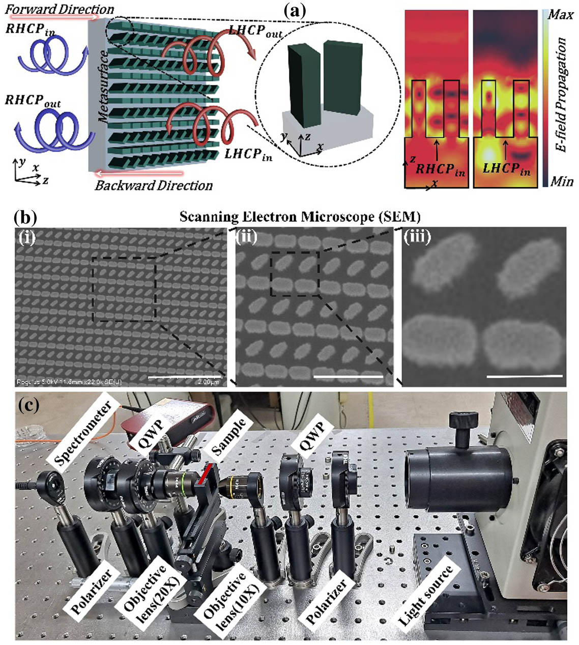
Figure 1.Working principle of the single-layered all-dielectric diatomic metasurface and optical setup. (a) Schematic image of the working principle of the proposed diatomic metasurface introducing a giant chiro-optical effect in the visible regime. (b) SEM image of a portion of the fabricated diatomic metasurface. The scale bar is (i) 2 μm; (ii) 0.75 μm; (iii) 0.25 μm. (c) The characterization setup of the designed dielectric metasurface for giant chiro-optical effect. An arc lamp housing is used as the light source. A linear polarizer is used to linearly polarize the input beam, passing through a QWP to produce LHCP or RHCP light. The OL focuses on the polarized light, which illuminates the sample. The transmitted light beam from the sample further passes through another OL, QWP, and polarizer. Finally, the results are recorded by using a spectrometer.
As depicted in Fig. 1(c), an optical setup was built to characterize the fabricated metasurface and measure the chiro-optical effect. An arc lamp housing was used as the light source to illuminate the fabricated sample. The light passed through a linear polarizer and then through a quarter-wave plate (QWP) to create a circularly polarized (CP) beam. An objective lens (OL) was used to focus the CP beam and illuminate the sample. Further, the transmitted beam from the sample passed through another OL, QWP, and polarizer. Finally, the output beam was captured by the spectrometer.
The perspective view of the 3D building block of the diatomic metasurface is depicted in Fig. 2(a) and contains a pair of a-Si:H-based distinct nanofins. The designed metasurface behaves as a -symmetric structure breaking threefold or higher rotational symmetry and mirror symmetry in the metasurface plane. The diatomic metasurface is placed on a silicon dioxide () substrate. The ellipsometry data of the a-Si:H used for simulations are taken from Ref. [47]. The nanofins placed in the building block of the metasurface have a relative rotational angle of . Figure 2(b) illustrates the top view of the building block, with the structural parameters: ; ; ; ; displacement ; periodicity in the direction ; periodicity in the direction ; and height .
![]()
Figure 2.Optimization of the building block of the diatomic metasurface. (a) 3D perspective view of the building block of the metasurface containing a pair of distinct a-Si:H-based nanofins with a relative angle (
Simulations of the building block of the metasurface were done using the finite-difference time-domain (FDTD) method. Periodic boundaries were used in the and directions, with perfectly matched layer boundary conditions in the direction. The optimization process started with a parametric sweep of the length, width, and periodicity of the nanofins in the building block at a wavelength of 633 nm. In Figs. 2(c) and 2(d), the cross-polarized parameters (: LHCP transmission/RHCP incidence) and (: RHCP transmission/LHCP incidence) are plotted for the length and width of the left nanofin for RHCP and LHCP illuminations, respectively. Similarly, the cross-polarized parameters were plotted against the length and width of the right nanofin, keeping it at 45 deg of rotation angle relative to the first nanofin depicted in Figs. 2(e) and 2(f) for RHCP and LHCP illumination, respectively. The third parameter that affects the chirality of the proposed metasurface is the periodicity of the building block. This is shown in Figs. 2(g) and 2(h), where the cross-polarized parameters are plotted against the periodicity in the and directions for RHCP and LHCP illuminations, respectively. The length, width, and periodicity of the nanofins are chosen such that giant AT and optical activity are established through the structure. The red circles in Figs. 2(c)–2(h) indicate the chosen values of the length, width, and periodicity of the building block, leading to strong AT.
Figure 3(a) illustrates the simulated transmission coefficients (, LHCP transmission/RHCP incidence; , RHCP transmission/LHCP incidence; , LHCP transmission/LHCP incidence; and , RHCP transmission/RHCP incidence) of the diatomic metasurface for circularly polarized (CP) light against the wavelength for forward ( direction) illumination at normal incidence. The cross-polarized parameter for RHCP illumination shows maximum transmittance. In contrast, the cross-polarized parameter for LHCP in the backward ( direction) illumination shows maximum transmittance, as depicted in Fig. 3(b). Giant broadband AT and optical activity are observed. The experimentally measured results are illustrated in Figs. 3(d) and 3(e) for forward and backward direction illumination, respectively. The measured transmitted coefficients of the Jones matrix agree well with the simulated ones. Figures 3(c) and 3(f) represent the simulated and measured AT parameter [defined as the difference between cross-polarized parameters for RHCP and LHCP (i.e., and )], respectively for forward and backward illuminations. The simulated reflectance parameters are depicted in Figs. 3(g) and 3(h) for forward and backward illuminations, respectively. The small reflectance for just one coefficient of the Jones matrix around the wavelength of 633 nm for illumination in the forward direction of propagation (FP) and almost negligible reflectance for all the coefficients for incident light in the backward direction of propagation (BP) show maximum absorption. The CD is depicted in Figs. 3(i) and 3(j) for illumination in the forward and backward directions. Here, the CD is defined as the difference between absorption for LHCP and RHCP incident lights. The results demonstrate the average value of CD is for forward direction illumination, and the decrease is due to the reflection peak around the wavelength of 633 nm. In contrast, it exceeds this value for backward illumination. The AT of the proposed single-layered diatomic all-dielectric metasurface at 633 nm is , while the maximum value achieved at 640 nm is .
![]()
Figure 3.Representation of parameters of the Jones matrix for designed metasurface in transmission and reflection. The simulated coefficients of the Jones matrix in transmission (
![]()
Figure 4.AT parameter dependence on the incident angle of light. AT parameter in the forward direction for a wide range of incident angles in (a)
The proposed metasurface can be mathematically described by assuming that each nanofin in the building block acts as a half-wave plate (HWP) [68] with propagation phases and . Consequently, the Jones matrices in transmission for first (left) and second (right) nanofins for two linearly polarized illuminations with orthogonally polarized states can be written as
The optical response in the building block of the proposed metasurface depends on the combined effect of both nanofins. The building block also includes the coupling () between both nanofins. Hence, after converting the Jones matrices in Eqs. (1) and (2), it is more convenient to convert the Jones matrices in Eqs. (1) and (2) in a circular basis. In a circular basis, the Jones matrices can be expressed as [67]
Assuming that the phase difference between both nanofins along the fast axis is , the relative rotation , and , Eq. (3) becomes
It is noticeable that the proposed metasurface can transmit the light for RHCP illumination, i.e., , while suppressing the LHCP incident light, i.e., , in forward propagation. But the same metasurface yields opposite results for backward propagation.
To elucidate the origin of the induced giant chiro-optical effect in the proposed diatomic geometry, we evaluated the multipolar decomposition of exciting fields in each nanofin of the building block to check the individual contribution for LHCP and RHCP illumination in the forward direction [69–72]. The normalized multipolar resonances as a function of wavelength for the individual nanofins in the diatomic structure are depicted in Fig. 5. The red, blue, green, magenta, and black curves show the scattering power for electric dipole (ED) mode, magnetic dipole (MD) mode, toroidal dipole (TD) mode, electric quadrupole (EQ) mode, and magnetic quadrupole (MQ) mode, respectively. Figures 5(a) and 5(b) demonstrate the multipolar decomposition of scattering power for left and right nanofins of the building block for RHCP illuminations, respectively. These multipolar resonances in both nanofins participate in the constructive interference for maximum transmission of cross-polarized light.
![]()
Figure 5.Scattering power in terms of multipolar resonances. Calculated normalized multipolar decomposition for individual nanofins of the diatomic structure for (a), (b) RHCP and (c), (d) LHCP illumination in the forward direction. The red, blue, green, magenta, and black curves show the scattering power for the ED, MD, TD, EQ, and MQ modes, respectively.
Meanwhile, the multipolar resonances for LHCP incident light are depicted in Figs. 5(c) and 5(d). Unlike RHCP, the multipolar decomposition for both nanofins yields destructive interference and transmits the light with minimum amplitude. All the resonance modes contribute to giant chiro-optical effects, but the EQ and MD are the dominant ones for RHCP excitation and lead to maximum AT. At the same time, the EQ, MD, and TD are the main contributing multipolar resonances for LHCP to realize the maximum CD. The observed difference between the resonance modes for both RHCP and LHCP illuminations leads to the more robust linear chiro-optical effects.
Additionally, EM fields are depicted in Fig. 6 to confirm the nature of dominant modes in the left and right nanofins of the proposed diatomic structure in forward direction illumination. The normalized electric field distributions for both nanofins at the wavelengths of 550, 640, and 700 nm are depicted in Figs. 6(a)–6(f) for RHCP and Figs. 6(g)–6(i) for LHCP illumination. Similarly, the normalized magnetic field distributions for left and right nanofins at the same wavelengths are shown in Figs. 6(m)–6(r) for RHCP and Figs. 6(s)–6(x) for LHCP illumination. The blue lines with white arrows show the direction of electric currents. The individual contribution of nanofins in the constructive and destructive interferences can be well observed in Fig. 5 and Fig. 6 to realize the underlying mechanism behind the giant chiro-optical effect in the proposed geometry.
![]()
Figure 6.Electric and magnetic field distributions at different wavelengths in the visible regime. Calculated normalized EM field distributions at different wavelengths in the visible regime for the individual nanofins for RHCP and LHCP incident light. The normalized electric field distributions for the left and right nanofins at the wavelengths of 550, 640, and 700 nm for (a)–(f) RHCP and (g)–(i) LHCP illumination. Similarly, the normalized magnetic field distributions for the left and right nanofins at the wavelengths of 550, 640, and 700 nm for (m)–(r) RHCP and (s)–(x) LHCP illumination. The blue lines with white arrows show the direction of electric currents.
3. CONCLUSION
We demonstrated a single-layered dielectric metasurface that produces a giant chiro-optical effect. The metasurface utilizes a pair of achiral nanofins with distinct structural parameters as the building blocks to simultaneously break the in-plane and radial symmetries. Each nanofin behaves as a HWP, and their mutual coupling exhibits constructive and destructive interference with an extra degree of design freedom, leading to giant CD, AT, and optical activity. To the best of our knowledge, the proposed structure provides the largest AT for a compact single-layered chiral metasurface. Additionally, the underlying mechanism behind the chiro-optical effect is explained by multipolar decomposition and visualization of the EM fields inside the nanofins, which shows the excitation and coupling of the multipolar resonances. Our results prove that the proposed metasurface could have significant potential in chiral polarizers for optical displays [73], holograms [66,67,74], chiral sensing, CD spectroscopy, ultrathin polarization rotators, and shapers for integrated circuits and chiral beam splitters.
Acknowledgment
Acknowledgment. H. S. K. acknowledges the Ph.D. fellowship grant (PhDEE17003) by ITU Lahore, Pakistan. I. K. acknowledges the NRF Sejong Science fellowship (NRF-2021R1C1C2004291) funded by the Ministry of Science and ICT of the Korean government. T. L. acknowledges the NRF Global Ph.D. fellowship (NRF-2019H1A2A1076295) funded by the Ministry of Education of the Korean government. Y. K. acknowledges the Hyundai Motor Chung Mong-Koo fellowship and the POSTECHIAN fellowship. J. K. acknowledges the POSTECH Alchemist fellowship. M. Q. M., M. Z., and K. R. acknowledge an internal research grant by ITU Lahore, Pakistan.
References
[1] V. A. Fedotov, A. S. Schwanecke, N. I. Zheludev, V. V. Khardikov, S. L. Prosvirnin. Asymmetric transmission of light and enantiomerically sensitive plasmon resonance in planar chiral nanostructures. Nano Lett., 7, 1996-1999(2007).
[2] J. K. Gansel, M. Thiel, M. S. Rill, M. Decker, K. Bade, V. Saile, G. Von Freymann, S. Linden, M. Wegener. Gold helix photonic metamaterial as broadband circular polarizer. Science, 325, 1513-1515(2009).
[3] M. Hentschel, M. Schäferling, T. Weiss, N. Liu, H. Giessen. Three-dimensional chiral plasmonic oligomers. Nano Lett., 12, 2542-2547(2012).
[4] Y. Zhao, A. N. Askarpour, L. Sun, J. Shi, X. Li, A. Alù. Chirality detection of enantiomers using twisted optical metamaterials. Nat. Commun., 8, 14180(2017).
[5] S. Fasold, S. Linß, T. Kawde, M. Falkner, M. Decker, T. Pertsch, I. Staude. Disorder-enabled pure chirality in bilayer plasmonic metasurfaces. ACS Photon., 5, 1773-1778(2018).
[6] M. Decker, M. Ruther, C. E. Kriegler, J. Zhou, C. M. Soukoulis, S. Linden, M. Wegener. Strong optical activity from twisted-cross photonic metamaterials. Opt. Lett., 34, 2501-2503(2009).
[7] A. F. Koenderink, A. Polman. Nanophotonics: shrinking light-based technology. Science, 348, 516-521(2015).
[8] V. K. Valev, J. J. Baumberg, C. Sibilia, T. Verbiest. Chirality and chiroptical effects in plasmonic nanostructures: fundamentals, recent progress, and outlook. Adv. Mater., 25, 2517-2534(2013).
[9] A. B. Khanikaev, N. Arju, Z. Fan, D. Purtseladze, F. Lu, J. Lee, P. Sarriugarte, M. Schnell, R. Hillenbrand, M. A. Belkin, G. Shvets. Experimental demonstration of the microscopic origin of circular dichroism in two-dimensional metamaterials. Nat. Commun., 7, 12045(2016).
[10] Z. Wang, F. Cheng, T. Winsor, Y. Liu. Optical chiral metamaterials: a review of the fundamentals, fabrication methods and applications. Nanotechnology, 27, 412001(2016).
[11] Z. Wang, H. Jia, K. Yao, W. Cai, H. Chen, Y. Liu. Circular dichroism metamirrors with near-perfect extinction. ACS Photon., 3, 2096-2101(2016).
[12] L. Kang, S. Rodrigues, M. Taghinejad, S. Lan, K. Lee, Y. Liu, D. H. Werner, A. Urbas, W. Cai. Preserving spin states upon reflection: linear and nonlinear responses of a chiral meta-mirror. Nano Lett., 17, 7102-7109(2017).
[13] M. Thiel, M. Decker, M. Deubel, M. Wegener, S. Linden, G. Von Freymann. Polarization stop bands in chiral polymeric three-dimensional photonic crystals. Adv. Mater., 19, 207-210(2007).
[14] M. Thiel, M. S. Rill, G. Von Freymann, M. Wegener. Three-dimensional bi-chiral photonic crystals. Adv. Mater., 21, 4680-4682(2009).
[15] B. Frank, X. Yin, M. Schäferling, J. Zhao, S. M. Hein, P. V. Braun, H. Giessen. Large-area 3D chiral plasmonic structures. ACS Nano, 7, 6321-6329(2013).
[16] A. V. Rogacheva, V. A. Fedotov, A. S. Schwanecke, N. I. Zheludev. Giant gyrotropy due to electromagnetic-field coupling in a bilayered chiral structure. Phys. Rev. Lett., 97, 177401(2006).
[17] C. Menzel, C. Helgert, C. Rockstuhl, E. B. Kley, A. Tünnermann, T. Pertsch, F. Lederer. Asymmetric transmission of linearly polarized light at optical metamaterials. Phys. Rev. Lett., 104, 253902(2010).
[18] C. Pfeiffer, C. Zhang, V. Ray, L. J. Guo, A. Grbic. High performance bianisotropic metasurfaces: asymmetric transmission of light. Phys. Rev. Lett., 113, 023902(2014).
[19] M. Mutlu, E. Ozbay. A transparent 90 polarization rotator by combining chirality and electromagnetic wave tunneling. Appl. Phys. Lett., 100, 051909(2012).
[20] K. Tanaka, D. Arslan, S. Fasold, M. Steinert, J. Sautter, M. Falkner, T. Pertsch, M. Decker, I. Staude. Chiral bilayer all-dielectric metasurfaces. ACS Nano, 14, 15926-15935(2020).
[21] S. S. Bukhari, J. Vardaxoglou, W. Whittow. A metasurfaces review: definitions and applications. Appl. Sci., 9, 2727(2019).
[22] T. Kelvin. The Molecular Tactics of a Crystal(1894).
[23] W. T. B. Kelvin. Baltimore Lectures on Molecular Dynamics and the Wave Theory of Light(1904).
[24] S. Vignolini, E. Moyroud, B. J. Glover, U. Steiner. Analysing photonic structures in plants. J. R. Soc. Interface, 10, 20130394(2013).
[25] V. Sharma, M. Crne, J. O. Park, M. Srinivasarao. Structural origin of circularly polarized iridescence in jeweled beetles. Science, 325, 449-451(2009).
[26] V. Saranathan, C. O. Osuji, S. G. J. Mochrie, H. Noh, S. Narayanan, A. Sandy, E. R. Dufresne, R. O. Prum. Structure, function, and self-assembly of single network gyroid (
[27] R. M. Hazen, D. S. Sholl. Chiral selection on inorganic crystalline surfaces. Nat. Mater., 2, 367-374(2003).
[28] I. Čorić, B. List. Asymmetric spiroacetalization catalysed by confined brønsted acids. Nature, 483, 315-319(2012).
[29] F. Kamarei, A. Tarafder, F. Gritti, P. Vajda, G. Guiochon. Determination of the adsorption isotherm of the naproxen enantiomers on (S,S)-Whelk-O1 in supercritical fluid chromatography. J. Chromatogr. A, 1314, 276-287(2013).
[30] B. S. Sekhon. Exploiting the power of stereochemistry in drugs: an overview of racemic and enantiopure drugs. J. Mod. Med. Chem., 1, 10-36(2013).
[31] D. J. Cordato, L. E. Mather, G. K. Herkes. Stereochemistry in clinical medicine: a neurological perspective. J. Clin. Neurosci., 10, 649-654(2003).
[32] M. E. Franks, G. R. Macpherson, W. D. Figg. Thalidomide. Lancet, 363, 1802-1811(2004).
[33] J. Hu, M. Lawrence, J. A. Dionne. High quality factor dielectric metasurfaces for ultraviolet circular dichroism spectroscopy. ACS Photon., 7, 36-42(2020).
[34] T. Naeem, A. S. Rana, M. Zubair, T. Tauqeer, M. Q. Mehmood. Breaking planar symmetries by a single layered metasurface for realizing unique on-chip chiroptical effects. Opt. Mater. Express, 10, 3342-3352(2020).
[35] M. L. Solomon, J. Hu, M. Lawrence, A. García-Etxarri, J. A. Dionne. Enantiospecific optical enhancement of chiral sensing and separation with dielectric metasurfaces. ACS Photon., 6, 43-49(2019).
[36] S. Sun, Z. Zhou, C. Zhang, W. Yang, Q. Song, S. Xiao. All-dielectric meta-reflect array for efficient control of visible light. Ann. Phys., 530, 1700418(2018).
[37] M. A. Ansari, T. Tauqeer, M. Zubair, M. Q. Mehmood. Breaking polarisation-bandwidth trade-off in dielectric metasurface for unpolarised white light. Nanophotonics, 9, 963-971(2020).
[38] M. R. Akram, M. Q. Mehmood, T. Tauqeer, A. S. Rana, I. D. Rukhlenko, W. Zhu. Highly efficient generation of Bessel beams with polarization insensitive metasurfaces. Opt. Express, 27, 9467-9480(2019).
[39] M. A. Ansari, I. Kim, D. Lee, M. H. Waseem, M. Zubair, N. Mahmood, T. Badloe, S. Yerci, T. Tauqeer, M. Q. Mehmood, J. Rho. A spin-encoded all-dielectric metahologram for visible light. Laser Photon. Rev., 13, 1900065(2019).
[40] H. S. Khaliq, I. Kim, K. Riaz, T. Naeem, M. Zubair, J. Rho, M. Q. Mehmood. Chiroptical effect induced by achiral structures for full-dimensional manipulation of optical waves. Proc. SPIE, 11695, 116951M(2021).
[41] T. Naeem, A. S. Rana, H. S. Khaliq, T. Tauqeer, M. Zubair, M. Q. Mehmood. C2 symmetric single-layered meta-atoms for asymmetric holography. Proc. SPIE, 11710, 1171007(2021).
[42] T. Naeem, H. S. Khaliq, M. Zubair, T. Tauqeer, M. Q. Mehmood. Engineering tunability through electro-optic effects to manifest a multifunctional metadevice. RSC Adv., 11, 13220-13228(2021).
[43] H. S. Khaliq, M. R. Akram, K. Riaz, M. A. Ansari, J. Akbar, J. Zhang, W. Zhu, D. Zhang, X. Wang, M. Zubair, M. Q. Mehmood. Single-layered meta-reflectarray for polarization retention and spin-encrypted phase-encoding. Opt. Express, 29, 3230-3242(2021).
[44] H. S. Khaliq, K. Riaz, M. Zubair, M. A. Ansari, M. R. Akram, T. Naeem, J. Zhang, W. Zhu, D. Zhang, X. Wang, M. Q. Mehmood. Highly efficient metamirror with circular dichroism and wavefront engineering. Proc. SPIE, 11344, 113441N(2020).
[45] A. S. Rana, M. Q. Mehmood, H. Jeong, I. Kim, J. Rho. Tungsten-based ultrathin absorber for visible regime. Sci. Rep., 8, 2443(2018).
[46] M. Q. Mehmood, S. Mei, S. Hussain, K. Huang, S. Y. Siew, L. Zhang, T. Zhang, X. Ling, H. Liu, J. Teng, A. Danner, S. Zhang, C. W. Qiu. Visible-frequency metasurface for structuring and spatially multiplexing optical vortices. Adv. Mater., 28, 2533-2539(2016).
[47] N. Mahmood, I. Kim, M. Q. Mehmood, H. Jeong, A. Akbar, D. Lee, M. Saleem, M. Zubair, M. S. Anwar, F. A. Tahir, J. Rho. Polarisation insensitive multifunctional metasurfaces based on all-dielectric nanowaveguides. Nanoscale, 10, 18323-18330(2018).
[48] K. Huang, H. Liu, S. Restuccia, M. Q. Mehmood, S. T. Mei, D. Giovannini, A. Danner, M. J. Padgett, J. H. Teng, C. W. Qiu. Spiniform phase-encoded metagratings entangling arbitrary rational-order orbital angular momentum. Light Sci. Appl., 7, 17156(2018).
[49] S. Mei, M. Q. Mehmood, S. Hussain, K. Huang, X. Ling, S. Y. Siew, H. Liu, J. Teng, A. Danner, C. W. Qiu. Flat helical nanosieves. Adv. Funct. Mater., 26, 5255-5262(2016).
[50] Y. Chen, J. Gao, X. Yang. Direction-controlled bifunctional metasurface polarizers. Laser Photon. Rev., 12, 1800198(2018).
[51] E. Plum, V. A. Fedotov, N. I. Zheludev. Asymmetric transmission: a generic property of two-dimensional periodic patterns. J. Opt., 13, 024006(2011).
[52] S. Yang, Z. Liu, S. Hu, A. Z. Jin, H. Yang, S. Zhang, J. Li, C. Gu. Spin-selective transmission in chiral folded metasurfaces. Nano Lett., 19, 3432-3439(2019).
[53] Z. Li, W. Liu, H. Cheng, D. Y. Choi, S. Chen, J. Tian. Spin-selective full-dimensional manipulation of optical waves with chiral mirror. Adv. Mater., 32, 1907983(2020).
[54] L. Zhang, P. Zhou, H. Chen, H. Lu, H. Xie, L. Zheng, E. Li, J. Xie, L. Deng. Ultrabroadband design for linear polarization conversion and asymmetric transmission crossing X- and K-band. Sci. Rep., 6, 33826(2016).
[55] W. Li, Z. J. Coppens, L. V. Besteiro, W. Wang, A. O. Govorov, J. Valentine. Circularly polarized light detection with hot electrons in chiral plasmonic metamaterials. Nat. Commun., 6, 8379(2015).
[56] W. Ma, F. Cheng, Y. Liu. Deep-learning-enabled on-demand design of chiral metamaterials. ACS Nano, 12, 6326-6334(2018).
[57] K. Tanaka, D. Arslan, S. Fasold, M. Steinert, J. Sautter, M. Falkner. Chiral bilayer all-dielectric metasurfaces. ACS Nano, 14, 15926-15935(2020).
[58] A. B. Evlyukhin, S. M. Novikov, U. Zywietz, R. L. Eriksen, C. Reinhardt, S. I. Bozhevolnyi, B. N. Chichkov. Demonstration of magnetic dipole resonances of dielectric nanospheres in the visible region. Nano Lett., 12, 3749-3755(2012).
[59] V. A. Zenin, C. E. Garcia-Ortiz, A. B. Evlyukhin, Y. Yang, R. Malureanu, S. M. Novikov, V. Coello, B. N. Chichkov, S. I. Bozhevolnyi, A. V. Lavrinenko, N. A. Mortensen. Engineering nanoparticles with pure high-order multipole scattering. ACS Photon., 7, 1067-1075(2020).
[60] M. Decker, I. Staude, M. Falkner, J. Dominguez, D. N. Neshev, I. Brener, T. Pertsch, Y. S. Kivshar. High-efficiency dielectric Huygens’ surfaces. Adv. Opt. Mater., 3, 813-820(2015).
[61] T. V. Raziman, R. H. Godiksen, M. A. Müller, A. G. Curto. Conditions for enhancing chiral nanophotonics near achiral nanoparticles. ACS Photon., 6, 2583-2589(2019).
[62] F. Zhang, M. Pu, X. Li, P. Gao, X. Ma, J. Luo, H. Yu, X. Luo. All-dielectric metasurfaces for simultaneous giant circular asymmetric transmission and wavefront shaping based on asymmetric photonic spin–orbit interactions. Adv. Funct. Mater., 27, 1704295(2017).
[63] A. Y. Zhu, W. T. Chen, A. Zaidi, Y. W. Huang, M. Khorasaninejad, V. Sanjeev, C. W. Qiu, F. Capasso. Giant intrinsic chiro-optical activity in planar dielectric nanostructures. Light Sci. Appl., 7, 17158(2018).
[64] K. Yao, Y. Liu. Enhancing circular dichroism by chiral hotspots in silicon nanocube dimers. Nanoscale, 10, 8779-8786(2018).
[65] K. Yao, Y. Zheng. Near-ultraviolet dielectric metasurfaces: from surface-enhanced circular dichroism spectroscopy to polarization-preserving mirrors. J. Phys. Chem. C, 123, 11814-11822(2019).
[66] A. S. Rana, I. Kim, M. A. Ansari, M. S. Anwar, M. Saleem, T. Tauqeer, A. Danner, M. Zubair, M. Q. Mehmood, J. Rho. Planar achiral metasurfaces-induced anomalous chiroptical effect of optical spin isolation. ACS Appl. Mater. Interfaces, 12, 48899-48909(2020).
[67] H. S. Khaliq, I. Kim, J. Kim, D. K. Oh, M. Zubair, K. Riaz, M. Q. Mehmood, J. Rho. Manifesting simultaneous optical spin conservation and spin isolation in diatomic metasurfaces. Adv. Opt. Mater., 9, 2002002(2021).
[68] J. P. Balthasar Mueller, N. A. Rubin, R. C. Devlin, B. Groever, F. Capasso. Metasurface polarization optics: independent phase control of arbitrary orthogonal states of polarization. Phys. Rev. Lett., 118, 113901(2017).
[69] Z. Ma, S. M. Hanham, Y. Gong, M. Hong. All-dielectric reflective half-wave plate metasurface based on the anisotropic excitation of electric and magnetic dipole resonances. Opt. Lett., 43, 911-914(2018).
[70] T. Kaelberer, V. A. Fedotov, N. Papasimakis, D. P. Tsai, N. I. Zheludev. Toroidal dipolar response in a metamaterial. Science, 330, 1510-1512(2010).
[71] M. Qiu, L. Zhang, Z. Tang, W. Jin, C. Qiu, D. Y. Lei. 3D metaphotonic nanostructures with intrinsic chirality. Adv. Funct. Mater., 28, 1803147(2018).
[72] J. Mun, M. Kim, Y. Yang, C. Qiu, J. Rho. Electromagnetic chirality: from fundamentals to nontraditional chiroptical phenomena. Light Sci. Appl., 9, 139(2020).
[73] H. Lee, H.-Y. Ahn, J. Mun, Y. Y. Lee, M. Kim, N. H. Cho, K. Chang Kim, S. W. J. Rho, K. T. Nam. Amino-acid- and peptide-directed synthesis of chiral plasmonic gold nanoparticles. Nature, 556, 360-365(2018).
[74] I. Kim, M. A. Ansari, M. Q. Mehmood, W.-S. Kim, J. Jang, M. Zubair, Y.-K. Kim, J. Rho. Stimuli-responsive dynamic metaholographic displays with designer liquid crystal modulators. Adv. Mater., 32, 2004664(2020).

Set citation alerts for the article
Please enter your email address
© Copyright 2018-2021 | Chinese Laser Press. All Rights Reserved 沪ICP备15018463号-20