• Laser & Optoelectronics Progress
  • Vol. 57, Issue 7, 072203 (2020)
Chuchu Zhao1、**, Mingyong Hu1、*, Shaowei Zhang2, Xinglong Li2, and Zhaoyang Li1
Author Affiliations
  • 1Academy of Photoelectric Technology, Hefei University of Technology, Hefei, Anhui 230009, China
  • 2Shanghai Aerospace Control Technology Institute, Shanghai 201109, China
  • show less
    DOI: 10.3788/LOP57.072203 Cite this Article Set citation alerts
    Chuchu Zhao, Mingyong Hu, Shaowei Zhang, Xinglong Li, Zhaoyang Li. Research on Compensation Testing Method for Large-Aperture and High-Order Aspheric Surface[J]. Laser & Optoelectronics Progress, 2020, 57(7): 072203 Copy Citation Text show less
    Optical compensation system diagram based on spherical wave
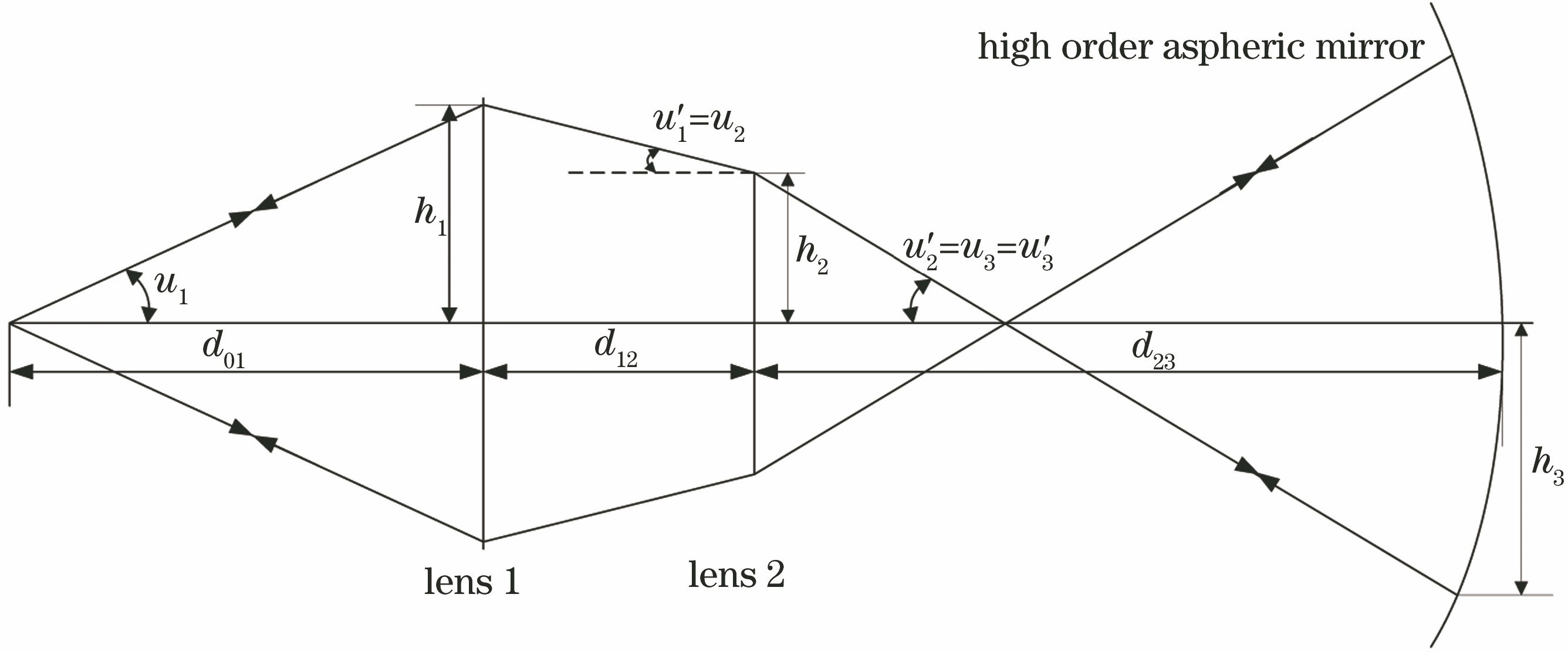
    Fig. 1. Optical compensation system diagram based on spherical wave
    Optical compensation system based on plane wave
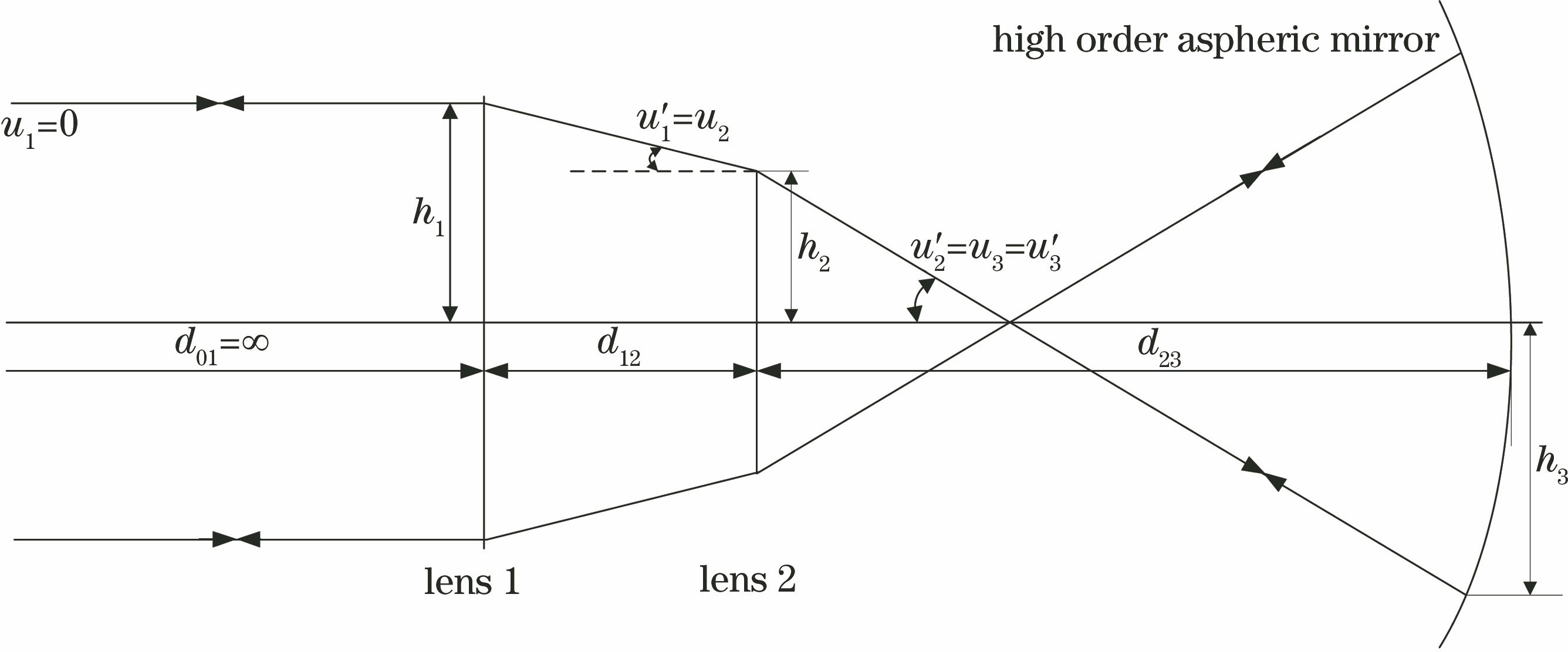
    Fig. 2. Optical compensation system based on plane wave
    Spot diagram and wavefront diagram of optical compensation system based on spherical wave. (a) Spot diagram; (b) wavefront diagram
    Fig. 3. Spot diagram and wavefront diagram of optical compensation system based on spherical wave. (a) Spot diagram; (b) wavefront diagram
    Spot diagram and wavefront diagram of optical compensation system based on plane wave. (a) Spot diagram; (b) wavefront diagram
    Fig. 4. Spot diagram and wavefront diagram of optical compensation system based on plane wave. (a) Spot diagram; (b) wavefront diagram
    Actual test chart. (a) Testing optical path; (b)interferogram of test result
    Fig. 5. Actual test chart. (a) Testing optical path; (b)interferogram of test result
    Radius /mmThickness /mmMediumDiameter /mm
    572.330air3.000
    -720.1200.000silica94.230
    -104.030180.190air93.230
    320.1500.000silica60.120
    -450.0002770.250air60.120
    -2580.000-2761.734mirror900.000
    Table 1. Structural parameters of initial compensation system based on spherical wave
    Radius /mmThickness /mmMediumDiameter /mm
    568.893air3.000
    -717.00013.448silica94.654
    -107.150165.577air95.268
    300.60010.900silica55.244
    -448.9962761.734air53.370
    -2580.000-2761.734mirror900.000
    Table 2. Structural parameters of optimized compensation system based on spherical wave
    Radius /mmThickness /mmMediumDiameter /mm
    air-
    -800.0000.000silica160.000
    -245.130300.000air160.000
    180.6700.000silica83.000
    280.4302850.300air83.000
    -2580.000-2850.300mirror900.000
    Table 3. Structural parameters of initial compensation system based on plane wave
    Radius /mmThickness /mmMediumDiameter /mm
    air-
    -791.48032.524silica157.570
    -241.580266.917air159.136
    176.71021.622silica83.846
    270.0002834.374air76.738
    -2580.000-2761.734mirror900.000
    Table 4. Structural parameters of optimized compensation system based on plane wave
    Theoretical valueActual value
    Radius /mmThickness /mmRadius /mmThickness /mm
    568.893569.398
    -717.00013.448-717.33213.412
    -107.150165.577-107.158164.808
    300.60010.900300.60311.018
    -448.9962761.734-448.9322761.740
    -2580.000-2761.734-2580.0002761.740
    Table 5. Structural parameters of measured compensation system
    Chuchu Zhao, Mingyong Hu, Shaowei Zhang, Xinglong Li, Zhaoyang Li. Research on Compensation Testing Method for Large-Aperture and High-Order Aspheric Surface[J]. Laser & Optoelectronics Progress, 2020, 57(7): 072203
    Download Citation