H. Peng, J.-R. Marquès, L. Lancia, F. Amiranoff, R. L. Berger, S. Weber, C. Riconda. Plasma optics in the context of high intensity lasers[J]. Matter and Radiation at Extremes, 2019, 4(6): 065401
Copy Citation Text
The use of plasmas provides a way to overcome the low damage threshold of classical solid-state based optical materials, which is the main limitation encountered in producing and manipulating intense and energetic laser pulses. Plasmas can directly amplify or alter the characteristics of ultra-short laser pulses via the three-wave coupling equations for parametric processes. The strong-coupling regime of Brillouin scattering (sc-SBS) is of particular interest: recent progress in this domain is presented here. This includes the role of the global phase in the spatio-temporal evolution of the three-wave coupled equations for backscattering that allows a description of the coupling dynamics and the various stages of amplification from the initial growth to the so-called self-similar regime. The understanding of the phase evolution allows control of the directionality of the energy transfer via the phase relation between the pulses. A scheme that exploits this coupling in order to use the plasma as a wave plate is also suggested.
I. INTRODUCTION
New fundamental physics effects originating from laser-matter interaction require very high laser intensities. This normally means ever shorter pulse lengths,1 as the available energy and the possibility to compress it is limited. The ever higher intensity in conjunction with the short pulse length presents major obstacles for the optical elements required to generate, transport, and focus the laser pulse due to the low damage threshold of materials which is less than 1 J/cm2.
Plasma optics exploits the fact that a laser interacting with a fully-ionized plasma is subject to feedback from the plasma itself, affecting its propagation and properties. A plasma can therefore be used in the same way as standard solid-state based optical materials. However, it differs in two fundamental ways. Due to the fact that in a plasma matter is already broken down, it can sustain much higher fluences than standard optical materials. This makes it particularly interesting for high-intensity laser pulses. As the laser modification is induced by the laser itself, the interaction is limited in time, and it does not substantially modify the initial plasma equilibrium. Plasma optics is therefore a transient or dynamical optical element, driven by the finite pulse length of the laser beam. In order to obtain a well-defined and “clean” effect on the coherent light, the modification time is given by either the characteristic pulse length or the plasma self-modification time (e.g., wave-breaking of a regular structure).
Controlled, regular interaction of lasers with plasmas normally implies the generation of repetitive entities such as oscillations in the medium. For low intensities of the driving force, the laser, this leads to the excitation of eigenmodes in the plasma, e.g., electron plasma waves or ion-acoustic waves. However, non-eigenmodes can be generated if the intensity is high enough, i.e., driven modes. They display very different characteristics and dispersion relations. In this paper special emphasis is given to one such mode, strong-coupling Brillouin backscattering,2 which has unique properties for plasma amplification (a prime example of plasma optics), where two laser pulses with the same frequency couple in a preformed plasma.3–16
In contrast, the use of ellipsoidal plasma mirrors (EPMs)17 to focus a laser beam is an example of a plasma optics element which is singular in nature and not repetitive.
In the last decade many applications of plasmas to manipulate and control intense coherent light have been proposed: plasma amplification (as mentioned and referenced above), Bragg gratings, polarizers, beam combining,18,19 holograms,20 plasma mirrors,21 focusing,17 and many more.
In this paper we show the excellent agreement between different simulation models and their predictive capabilities with respect to experiments. We then propose a novel application of laser-plasma interaction in the context of plasma optics: a wave plate. It exploits the sophisticated nature of the phase in the strong-coupling three-wave model, and can be easily tested in a set-up based on the most recent succesful experimental results.
The reminder of the paper is organized as follows. Section II provides a short description of the various stages of the strong-coupling regime of Brillouin scattering. The subsequent section, Sec. III, discusses the role of simulations in this context and summarizes recent experimental results. Section IV describes a proposal for a new scheme, a plasma wave plate, based on the phase aspects of the three-wave coupling process. Finally a conclusion is presented in Sec. V.
II. THE sc-SBS COUPLING SCHEME AND THE ROLE OF THE PHASE
We briefly recall the main stages of the interaction of two pulses with the same frequency coupling in a plasma, in the so-called strong coupling Stimulated Brillouin Scattering (sc-SBS) regime.2 It is convenient6,8 to express the pump, the seed, and the ion wave in terms of amplitude and phase: , , N = Neiφ, in order to obtain the three-wave equations:with and Λ = 2Ze2/memic2 being the coupling factors for the field and density perturbations, respectively. The coupling is essentially governed by the total phase on the right-hand sides of these equations: ϑ = φp − φs − φ. A first analysis that allows a definition of the different stages of the evolution of the pulses is done by neglecting the convection of the waves, i.e., the second terms on the left-hand sides of the equations. A more accurate analysis, including convection, for a specific case is reported in Sec. IV. We assume that the pump propagates from left to right, and that the seed is counter-propagating. In the following we also assume that initially the seed intensity is much smaller than the pump intensity Is0 ≪ I(p0).
A. Initial stage
At the beginning of the interaction, we set φp = φs = 0 without loss of generality. Since we are in the strong coupling regime, instead of taking an envelope of the usual driven ion acoustic wave equation , we can neglect the convection term (). This approximation is very robust and as a consequence the system of coupled equations does not reach a steady state as in the weak coupling regime. By recalling that the seed amplitude Es is real and combining with Eq. (6), we obtain
Then the density evolves as
Assuming all the amplitudes are positive and N is real, this implies that the initial phase of the density is φ = π and the total phase is ϑ = −π. One thus obtains the phase of the seed and the pump from Eqs. (4) and (2):
Since the seed is much less intense than the pump, the phase of the seed increases significantly, while the phase of the pump is practically unchanged.
The total phase evolves as and ∂tEp < 0 and ∂tEs > 0. The energy transfers from the pump to the seed. However, in this stage, both the seed and the ion density perturbation are very small and the energy transfer is therefore also very small. Neglecting the first term on the left-hand side of Eq. (5) we obtain the phase of the density in this stage, φ = π − φs/6, and the total phase is .
B. Exponential and self-similar stage
After the initial stage, both the seed and the ion wave grow exponentially. We write , , and . Then , while , . From Eqs. (3) and (4), we know that the total phase is almost constant: ϑ = −4π/3. Combined with the total phase expression one obtains the phase of the seed when it enters the exponential stage: φs = 2/5π. The estimated time for the seed phase to reach this value is γscti = 1.7, or more accurately γscti = 2.2 if one takes (correctly) into account the convective terms.8 During the exponential stage the phase of the pump is still basically unchanged. When the energy transfer is such that the intensity of the seed becomes comparable to the pump intensity, the system enters the so-called self-similar regime. During this stage the phase of the density varies very little, while the seed, the pump, and the global phase all vary significantly, creating a sort of wave train. The intensity of the first peak becomes very high, while the pulse gets compressed.
The understanding of these different stages can be used to design a plasma wave plate, as will be shown in more detail in Sec. IV. As we have seen in the initial stage (when the amplitude of the pump is much larger than that of the seed) the seed phase grows quickly while its amplitude does not change much. Indeed the seed phase grows as , where γsc depends on the amplitude of the pump and the plasma density. We can then exploit these characteristics by making sure that we stay always in the initial stage. That is, we consider a time of superposition of pump and seed (interaction time) not longer than .
III. PREDICTIVE CAPABILITIES OF SIMULATION
A. Dimensionality aspects
The coupled Eqs. (1)–(6) introduced and discussed in Sec. II prove to be a very powerful tool for understanding the sc-SBS regime and for proposing schemes that allow the manipulation of intense laser pulses. Even if they are limited to a 1D description (along the direction of propagation of the laser pulses in a counter-propagative geometry), the estimate that can be derived and their full numerical resolution turns out to be very effective in describing the interaction process in a realistic configuration. To justify this statement we have performed a systematic comparison of the solution of the coupled equations above with 2D and 3D simulations performed with pF3D.22,23 This code contains a number of extra features with respect to the envelope model described above, in addition to allowing a full 3D description. The pump laser light is coupled both to Brillouin and Raman backscattered or amplified light. Each light wave is described by a space envelope equation under the paraxial approximation. The Raman light frequency is downshifted from the pump by the plasma frequency. As in the 1D model the IAW is not enveloped in time, which allows a proper treatment of strongly-coupled SBS, while the electron plasma wave is spatially and temporally enveloped. The code includes the effect of background thermal noise, calculated by assuming thermal fluctuations in the plasma equilibrium and arbitrary pulse shapes and geometry between pump and seed. Heating by bremsstrahlung absorption is included as well as filamentation. A first test of the predictive capabilities of the modeling of the interaction by the pF3D code and by the simpler 1D system of Eqs. (1)–(6) was conducted by considering the problem of the amplification of a short seed by a long intense pump. The input laser-plasma parameters for the 3D envelope (pF3D) simulations are motivated by realistic (recent) experimental conditions.24 The spatial and temporal profiles are Gaussian. The plasma density has a peak value of ne/nc = 0.05, with a FWHM of 500 (750) μm along the z(y)-axis, respectively, and is constant along the x-axis. The ion temperature is Ti = 80 eV. The electron temperature is Te = 100 eV. The spatial resolutions are Δx = Δz = λ0 and Δy = 2λ0/3. The seed intensity is Is = 1015 W/cm2 and the pump intensity is Ip = 1.5 × 10¹⁶ W/cm2 (1D), or Ip,peak = 4 × 10¹⁶ W/cm2 (2D–3D).
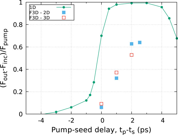
Both in past experiments4,5 and in theoretical papers,6 it has been shown that the maximum energy transfer depends on the pump-seed delay. It has also been shown that the three-wave sc-SBS coupling process is more efficient when the seed pulse propagates in a decreasing density ramp.6 This is what happens when the seed pulse arrives slightly before the pump, in a plasma described by a Gaussian profile. We have then performed a systematic comparison of the dependence of the energy transfer on the delay in 1D [Eqs. (1)–(6)] and 2D or 3D simulations by using the pF3D code. The results are presented in Fig. 1. As can be observed in the figure, the maximum energy transfer is always reached for a seed pulse arriving at the plasma center slightly before the pump (between 0.5 and 2.5 ps in the present cases). Even if all simulations show the same trend, the 1D simulations, which do not include spontaneous SBS and SRS, overestimate the energy exchange. Indeed the amplification is affected by the energy losses of the pump from its spontaneous backward SBS or SRS before the interaction with the seed. By sending the seed earlier, stimulated coupling is favored and more pump energy is available for the amplification process. As a consequence, the discrepancy between 1D and 2D–3D simulations decreases as the time delay increases. Another reason for the discrepancy between the 1D and 2D–3D simulations can also be understood in terms of purely geometrical effects. Since the both the pump and seed have a profile in the transverse direction, and they can couple at an angle, the local parameters spanned during the interaction can vary significantly. However, the overall process is the sum of all the local (1D along the propagation line) processes. Thus for example the wings of the seed pulse will be amplified less than the center resulting in an average overall energy exchange smaller in 2D–3D than in 1D. The improvement in amplification at the center of the seed is partially due to the fact that the coupling constant increases with the pump intensity. Another important effect, however, depends on the seed shape. Over a fixed interaction length, the energy exchange increases significantly with the seed intensity. This is shown in Fig. 2, where the energy exchange is reproduced as a function of the seed intensity, and for various situations with spontaneous Raman turned on or off. As can be seen, the increase in the energy exchange is dramatic when the seed intensity becomes a fraction of the pump intensity.
Figure 1.Percentage of the pump energy transferred to the seed as a function of the seed delay time. 1D simulations are labeled by line-point, 2D by blue circles, and 3D by red squares. At tp − ts = 0 ps, the peak power of the seed and pump arrive at the maximum electron density at the same time.
B. Comment with respect to recent experimental results
The simulation predictions of Joule-level energy transfer were confirmed for the first time in a recent experiment.24 There was also very good agreement as far as the characteristics of the amplified seed, such as spectrum and pulse length, are concerned. This experiment allowed the validation of several simulation predictions. For example, it was shown in a scan of initial seed intensity that a relatively high intensity allowed access to the self-similar regime in a very short time and boosted the energy transfer from pump to seed, as discussed above. It was also shown that the amplification process is optimized if the seed intensity is a few percent of the pump intensity. By contrast, a much lower seed intensity allows exploration of the initial stages of the interaction process for a longer time interval.
IV. NEW SCHEME BASED ON THE PHASE EVOLUTION DURING SC-SBS: PLASMA WAVE PLATE
A. Context
An interesting idea in the domain of plasma optics is to use the plasma to act as a wave plate, similar to a crystal wave plate. The plasma will impose a certain phase delay to the laser in one polarizing direction with respect to the other perpendicular direction. In contrast to crystals, however, this effect can be applied to intense laser pulses. The idea of controlling the polarization or the phase of a seed laser by adjusting the amplitude of the pump laser and the plasma density was recently proposed for weakly coupled stimulated Brillouin scattering.25 A two step process was also proposed26,27 by considering the generation of a plasma grating in the static ponderomotive potential of two identical lasers that can then be exploited to change the polarization or the phase in a specific direction of a third laser. These ideas are promising not only because they allow us to control the laser with other lasers and plasma. They also allow experimentalists to conveniently adjust the lasers to a desirable state close to the target, without sacrificing the beam quality by expanding the beam waist, and then change the polarization state with traditional crystal devices.
Some of the hypotheses used in the proposed scheme in the weak coupling SBS regime25 do not apply anymore in the sc-SBS regime, namely, the fact that a steady state is reached where the pump is basically unaffected (linear regime, analogous to what we define the exponential regime) and the transient coupling related to the early dynamics is negligible. This scheme then applies for relatively long and moderately intense laser pulses. For example, a 250 ps and 1011 W/cm2 seed was used in recent experiments.28,29 In contrast, the two step scheme, where a grating is created in the first step, is more suitable to shorter and more intense laser pulses. However, in order to use it as a wave plate it requires a good control of the grating generation, that should have very large density perturbations. The creation of such a grating and the dependence on the lasers and plasma parameters need to be further investigated.
The approach we propose is a single step scheme, but which can be applied to more intense and shorter pulses than have been considered so far. The idea is to use the plasma as a wave plate based on the phase evolution in the initial stage of sc-SBS.7,8
B. Scheme and theoretical analysis
We wish to take advantage of the properties of the coupling in the initial stage, namely, that the seed phase varies significantly, while its intensity and the pump intensity are basically unchanged. The corresponding scheme is shown in Fig. 3. An intense and short pump crosses the seed in a constant density plasma. The pump duration has to be smaller than or of the order of the total time of the initial stage ti to avoid exponential growth of the seed. The desired phase delay can be obtained by tuning the amplitude of the pump and the plasma density, up to the maximum phase delay that can be obtained for the seed during this stage, that is 2/5π.
Figure 3.The basic scheme using a plasma as a wave plate based on the phase evolution during the sc-SBS amplification.
The interaction zone is defined by vg(t − T) ≤ (x − x0) ≤ vgt, where x0 is the crossing point, and starts at t = 0. Here T is the pump duration, which is much smaller than the seed duration Ts. The initial time (T/2) necessary for the pump and the seed to fully overlap is not considered in the following; this corresponds to the initial part of the seed −vgt ≤ (x − x0) ≤ −vg(t − T/2), and the seed phase grows from zero to its saturation value for the given scheme. The rest of the seed gains the same phase increment after passing through the interaction zone that corresponds to the saturation value. We can describe the process initially by considering the evolution equation for the density:
We can rewrite these equations in the seed frame: X = x + vgt, τ = t. From Eq. (4), we haveand
The seed phase is than obtained by integrating in the interaction zone:
So the seed phase is
Transforming back to the x, t frame, we have
As a result, the seed gains everywhere (except for the very first part) a phase of after the interaction with the pump. This analytical estimate of the phase gained by the seed is valid only if the pump duration is less than the limiting value where the system enters the exponential regime (). If the pump duration gets closer to ti the process still works, but the formula overestimates the change in phase,8 which in any case will not exceed 2π/5. To obtain the exact value of the phase shift, we have to solve the full system numerically.
C. Simulations and proposed experimental setup
In this section we consider the numerical solution of the three-wave envelope equations. The first case considered involves both the pump and the seed having a flat-topped distribution, and is reproduced in Fig. 4, where the amplitudes |Ep|, |Es| and phases ϕ(Ep), ϕ(Es) are recorded. The pump propagates from left to right and the seed vice versa. The pump and the seed have the same wavelength of 1058 nm. The intensity of the pump and the seed are Ip = 1015 W/cm2 and Is = 1012 W/cm2, respectively. The duration of the pump and the seed are T = 478 fs and Ts = 1900 fs, respectively. The plasma density is 0.1nc. The dotted lines are the phase of the pump and the seed, respectively. The strong coupling factor is given by ,6 where I15 is the laser intensity in units of 1015 W/cm2 and λ0 is the laser wavelength in units of μm. The time of the initial stage is for our simulation parameters, i.e., of the same order as the pump duration T.
Figure 4.The amplitudes and phases of the pump and the seed at different times. Both the amplitudes of the pump and the seed are normalized to the amplitude of the pump. The phases are normalized to π. The plasma density is constant in the simulation box.
In Fig. 4 we can clearly see that the seed gains a constant phase of about 0.3π after the interaction with the pump, apart from the front part, which increases linearly. For the sake of completeness we also note that in the figure the pump develops a tail with a phase close to 0.8π. This can be explained by considering the reflection of the seed by the ion wave, which in this stage has a constant phase π. From the pump equation of the three-wave equations, ∂tEp = −iμNEs (convection is neglected here), it is readily seen that the phase of the part trailing the main spike of the pump is φpt = −π/2 + π + φs = 0.8π, which agrees with the simulation. The π/2 phase of the seed trailing the main seed in the last panel, in the interaction zone, can also be explained by ∂tEs = −iμN∗Ep and φst = −π/2 − π − φp = −1.5π, which is equivalent to 0.5π here.
We next perform the simulation with a Gaussian pump and a Gaussian seed. The same parameters are used in this simulation as the previous one, but the Gaussian pump is cut off at 1.5T from its maximum value and the seed is cut off at Ts. The results are shown in Fig. 5. There is still a gain in phase for the seed from the interaction with the pump, but it is not constant, even if it is slowly varying. In this configuration the seed is also slightly amplified. In order to improve the phase change of the seed, so that it is constant for the whole seed duration, one should consider a super-Gaussian profile, or a chirped pump, chirped seed, or plasma with a density gradient can be used in order to balance the phase difference along the seed and suppress its amplification.8 This will not be discussed here and is left for future study.
Figure 5.The amplitudes and phases of the pump and the seed at different times. All the parameters are identical to Fig. 4 except that Gaussian pulses are used here.
As long as the seed is much weaker than the pump, i.e., Es ≪ Ep, the pump duration is the only limiting factor for the interaction always being in the initial stage, leading to insignificant energy transfer from the pump to the seed (this is true even for a seed with larger amplitude than that in Figs. 4 and 5). But if the coupling is larger, a strong ion acoustic wave is generated that creates a tail in the pump and corresponds to scattering the energy from the seed to the pump. This effect is seen in the current simulations, but it is negligible (the small lump after the main spike of pump in Figs. 4 and 5). However, an upper limit on the seed amplitude or the seed duration can be found, beyond which the rear part of seed is depleted. This has been verified by simulation (not shown here). For a seed with a given amplitude, the largest duration is given by or, vice versa, this condition gives the largest amplitude of a seed with a given duration. For example, a seed with intensity Is = 1013 W/cm2 cannot have a duration longer than about 890 fs, although this depletion can be alleviated by attenuating the plasma density.
V. CONCLUSION
In this paper we gave a brief overview of plasma amplification using strong-coupling Brillouin backscattering and in particlar discussed the various stages during the amplification process, and the global phase variation in the coupling process at each stage. The importance of the phase in the three-wave coupling equations was clearly described. As a new concrete example of the global phase in the amplification process a scheme was proposed which exploits the temporal evolution of this phase in order to generate, in a controlled way, a wave plate to affect the polarization of the amplified seed. This is of particular interest to high-power, short-pulse laser beams, as standard optics cannot easily change the polarization of a high-intensity beam. This article aims to draw attention to the growing importance of plasma optics in the context of high-power beams and its unique possibilities to manipulate coherent light.
H. Peng, J.-R. Marquès, L. Lancia, F. Amiranoff, R. L. Berger, S. Weber, C. Riconda. Plasma optics in the context of high intensity lasers[J]. Matter and Radiation at Extremes, 2019, 4(6): 065401