Abstract
Photonic crystals have revolutionized the field of optics with their unique dispersion and energy band gap engineering capabilities, such as the demonstration of extreme group and phase velocities, topologically protected photonic edge states, and control of spontaneous emission of photons. Time-variant media have also shown distinct functionalities, including nonreciprocal propagation, frequency conversion, and amplification of light. However, spatiotemporal modulation has mostly been studied as a simple harmonic wave function. Here, we analyze time-variant and spatially discrete photonic crystal structures, referred to as spatiotemporal crystals. The design of spatiotemporal crystals allows engineering of the momentum band gap within which parametric amplification can occur. As a potential platform for the construction of a parametric oscillator, a finite-sized spatiotemporal crystal is proposed and analyzed. Parametric oscillation is initiated by the energy and momentum conversion of an incident wave and the subsequent amplification by parametric gain within the momentum band gap. The oscillation process dominates over frequency mixing interactions above a transition threshold determined by the balance between gain and loss. Furthermore, the asymmetric formation of momentum band gaps can be realized by spatial phase control of the temporal modulation, which leads to directional radiation of oscillations at distinct frequencies. The proposed structure would enable simultaneous engineering of energy and momentum band gaps and provide a guideline for implementation of advanced dispersion-engineered parametric oscillators.1. INTRODUCTION
Since the discovery of photonic crystals (PCs) that support energy band gaps (EBGs) [1,2], the design of materials with photonic band structures has led to the realization of test platforms for fundamental physics and broad engineering applications [3]. These advancements can be clearly seen in the observation of exotic light propagation characteristics, such as the realization of left-handed materials [4], extreme group and phase velocities [5,6], and topologically protected photonic edge states [7,8]. In addition, the EBGs in PCs have been utilized to create integrated and miniaturized photonic platforms for manipulating the flow of light [9]. Within the frequency range of photonic EBGs, photons are localized in the defective region of spatially periodic structures due to the absence of available photonic states in the surroundings. The ability to confine photons on a wavelength scale has been exploited in diverse areas of physics and engineering, especially for enhancing spontaneous emission of photons [1,2,10], implementing micro/nanolasers [11,12], boosting optical nonlinear effects [13,14], and developing photonic crystal fibers [15] and on-chip photonic integrated circuits [16–18].
In line with the diverse research activities on PCs, time-variant media have been investigated due to their distinct functionalities, such as nonreciprocal propagation, frequency conversion, Floquet engineering, and light amplification [19–28]. Among these, one of the most significant developments is the observation of nonreciprocal wave propagation in media with traveling-wave-like spatiotemporal modulation. In such media, an asymmetrical band structure can be formed with respect to reversal of a wavevector, and this asymmetry makes it possible to observe the nonreciprocal propagation of waves [19–23]. Furthermore, spatiotemporal modulation can modify not only the symmetry of band structures but also their topological properties. For example, warping of the band structure by spatiotemporal modulation can change the Chern number of bands, allowing the observation of Floquet topological insulators [24,25] and the modulation-induced anomalous Hall effect [26,27]. All these advancements indicate that spatiotemporal modulation of media has the potential to provide an unprecedented approach to designing band structures for photons, phonons, and potentially electrons.
Compared with spatially periodic PCs, a completely distinct dispersion relation has been predicted for media with a temporally periodic property [29–31]. In these media, momentum band gaps (MBGs) can be opened, leading to parametric amplification of electromagnetic waves. The concept of MBGs dates back to the 1960s; in the seminal work by Cassedy [32,33], traveling-wave-type permittivity modulation was considered for an otherwise spatially homogeneous medium. Particularly, it was shown that MBGs emerge when a medium is modulated in the form of a simple harmonic wave at a superluminal phase velocity, and unstable solutions of exponentially growing and decaying oscillatory waves with complex-valued frequencies exist [34,35]. Since then, discussions have been extended to take into account more complicated cases of a slab with finite thickness [36–39], intrinsically dispersive media [40], and even phononic lattices [23,41]. These early works showed that MBGs are opened when positive-frequency and negative-frequency branches of an unmodulated dispersion curve are coupled via the modulating harmonic wave.
Sign up for Photonics Research TOC. Get the latest issue of Photonics Research delivered right to you!Sign up now
Previously, the properties of time-variant media were investigated mostly for cases in which the spatiotemporal modulation was in the form of a simple harmonic wave. However, such an assumption is inadequate for the description of potential configurations with sophisticated spatial structures. Here we generalize the analysis to include spatiotemporal crystals (SCs), i.e., time-variant media with PC-like spatial structures, by considering multiple spatial frequencies of the spatiotemporal modulation. This generalization allows us to take full advantage of the dispersion engineering capability in PCs, as well as the additional degree of freedom from spatiotemporal modulation. Therefore, the design of SCs makes it possible to engineer the MBG within which parametric amplification occurs. As a platform for the construction of a parametric oscillator, a finite-sized SC is proposed and analyzed. The SC is composed of a one-dimensional array of thin slabs with temporally periodically modulated permittivity. Characterization of the finite-sized SC reveals that parametric oscillation is observed when a transition threshold is reached by increasing the normalized permittivity variation. Furthermore, spatial phase control of the temporal modulation leads to asymmetric formation of MBGs and directional radiation of oscillations at distinct frequencies from the finite-sized spatiotemporal crystal.
2. OPENING OF A MOMENTUM BAND GAP IN SCs
A. Mode Evolution in SCs
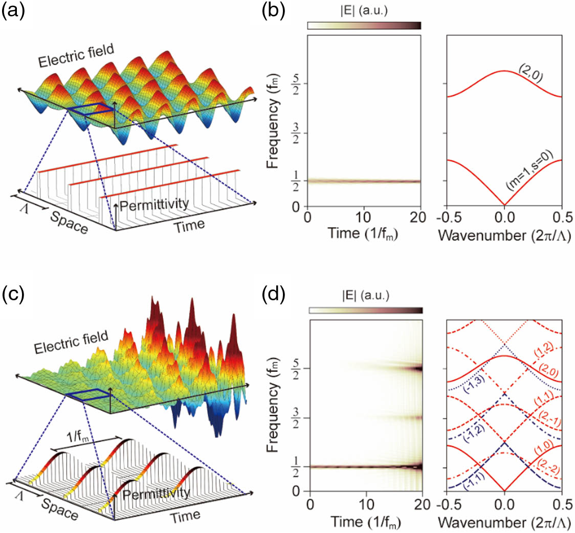
Figure 1.Spatiotemporal field evolution of the lowest-order PC mode. (a) Permittivity profile in space-time for a time-invariant PC, and spatiotemporal electric field distribution of a lowest order PC eigenmode. (b) Time-resolved spectral amplitude (left panel) and dispersion diagram (right panel) of the time-invariant PC. The spectral amplitude is invariant with respect to time (left panel). Note that the frequency axis is normalized to the modulation frequency. (c) Permittivity profile in space-time for an SC and spatiotemporal electric field distribution of the lowest-order PC eigenmode. The originally launched PC eigenmode has evolved into a mode with growing intensity. (d) Time-resolved spectral amplitude (left panel) and PC dispersion curve along with its temporally scattered bands (right panel). Three major frequency components are seen clearly in the left panel. The line color and style represent the sign of the frequency and mixing order, respectively.
B. Dispersion Diagrams of SCs

Figure 2.Dispersion diagrams of a PC and SCs. (a) Permittivity profile in space-time (top panel) and dispersion diagram of the PC. The two lowest bands are clearly shown in the middle and bottom panels. (b) Permittivity profile in space-time and dispersion diagram of the SC modulated at . Red lines are the dispersion curves calculated using the ST-PWEM. The lowest panels are the imaginary parts of the eigenfrequencies corresponding to the MBGs denoted by A and B in the middle panel. The MBGs denoted by A and B are classified as (1, 0; , 1) and (1, 1; , 2), respectively. (c) Permittivity profile in space-time and dispersion diagram of the SC modulated at . The MBGs denoted by A and B are classified as (1, 0; , 2) and (1, 0; , 1), respectively. (d) Permittivity profile in space-time and dispersion diagram of the SC modulated at . The MBG denoted by A is classified as (1, 0; , 2). For comparison, one of the EBGs is shown and denoted by B. (e) Permittivity profile in space-time and dispersion diagram of the SC modulated at . The MBGs denoted by A and B are classified as (1, 0; , 1) and (1, 0; , 2), respectively.
The periodic temporal modulation of the permittivity allows the existence of additional temporally scattered modes. The frequencies of these modes are shifted by integer multiples of the modulation frequency from the original frequencies. The collection of these additional modes is represented by dispersion curves that are shifted with respect to that calculated from a time-invariant PC. Consequently, the initial and all of the shifted dispersion curves may intersect each other [as schematically shown in the right panels of Fig. 1(d)]. Near the crossings where mode coupling exists, the modes can repel each other to create an MBG or an EBG. Note that in this paper, the term band gap is used to describe both band gaps and mode gaps. Specifically, MBGs are observed when strongly interacting modes in the dispersion curves have frequencies of opposite signs [for example, see A and B in Fig. 2(b)], while EBGs are observed when strongly interacting modes in the dispersion curves have frequencies of the same sign [for example, see B in Fig. 2(d)]. This is consistent with previous knowledge on the conditions for band gap formation [35]. Superluminal modulation mediates interactions between the modes with frequencies of opposite signs, whereas subluminal modulation mediates interactions between the modes with frequencies of the same sign. The opening of EBGs or MBGs is clearly illustrated in the middle panels of Figs. 2(b)–2(d). Depending on the Floquet–Bloch modes participating in the interaction, an MBG can be labeled with (, ; , ). For example, the MBGs denoted by A and B in Fig. 2(b) are formed as a result of the interaction between the positive- and negative-frequency lowest-order modes and are classified as (1, 0; , 1) and (1, 1; , 2), respectively.
When considering only the lowest-order photonic band that starts from the origin of the dispersion diagram, MBGs are generally located at odd integer multiples of half the modulation frequency, which can be simply inferred from the axial symmetry of the lowest-order band of a PC with respect to reversal of frequency. Because of the spatial periodicity, however, the lowest-order photonic band deviates from the linear relation with increasing wavenumber and exhibits zero group velocity at the band edge . Therefore, over a certain modulation frequency (i.e., , where denotes the cutoff frequency of the lowest-order PC band), the dispersiveness of the lowest-order photonic band results in the absence of MBGs at the odd integer multiples of half the modulation frequency [for example, note the absence of an MBG at in Fig. 2(d)]. Furthermore, the presence of higher-order photonic bands in a PC leads to the formation of MBGs whose frequencies cannot be expressed as odd integer multiples of half the modulation frequency [for example, see the MBG denoted by A in Figs. 2(c) and 2(d)]. The MBG frequencies are not expressed as odd integer multiples of half the modulation frequency when the following two conditions are satisfied: (1) and (2) . The first condition states that the interacting modes should have frequencies of opposite signs, which is a necessary condition for the formation of an MBG. The second condition requires that the interacting modes have different mode orders. In this case, the two interacting modes generally do not form a standing wave and thus create an MBG with nonzero group velocity [for example, see the MBG denoted by A in Fig. 2(e)]. Exceptions may exist in the case of accidental group velocity matching (); for example, see the MBG formed at the edge of the Brillouin zone denoted by B in Fig. 2(e).
Within the MBG, there exist two eigenfrequencies that are complex conjugates of each other with the same real part (describing the MBG frequency); one of the two imaginary parts is related to the parametric gain, while the other is related to the loss. The imaginary eigenfrequency, which gives the parametric gain within the MBG, is plotted below the bottom panels of Fig. 2. The two-dimensional Fourier-transformed field shows agglomerated spots within the MBG, which is related to the exponentially growing field [for example, see the bottom panel in Fig. 2(b)]. From the simulations, the width of the MBG and the imaginary eigenfrequency are found to increase with the normalized permittivity variation. When considered with the radiative loss of a finite-sized SC, the parametric gain determines the transition threshold for oscillation.
C. Spatiotemporal Mode Field Profiles at the Edges of MBGs
Figure 3.Spatiotemporal mode field profiles at the edges of an MBG. (a) Dispersion diagram of the SC modulated at . (b) Spatiotemporal permittivity profile of the PC unit cell used to calculate the dispersion curves. The parameters are identical to those used to calculate the dispersion curves in Fig. 2(b). (c) Numerically calculated spatiotemporal mode field profile at the lower wavenumber edge of the MBG. (d) Numerically calculated spatiotemporal mode field profile at the higher wavenumber edge of the MBG.
3. SC-BASED PARAMETRIC OSCILLATOR
A. Emergence of Parametric Oscillations at the MBG
Figure 4.Emergence of parametric oscillations at the MBG. (a) Schematic of a finite-sized SC (left panel). The electric fields of incident and transmitted waves are represented by and , respectively. The permittivities of constituting slabs are sinusoidally modulated in phase (right panel). (b) Transmitted field amplitude spectra for plotted as a function of the normalized permittivity variation. Two oscillating spectra are scaled to fit in the plot. (c) Transmitted field amplitude spectra for plotted as a function of the normalized permittivity variation. Four oscillating spectra are scaled to fit in the plot. The frequency of the input wave is set to 1.5 GHz for both (b) and (c). (d) Temporal field growth rates as a function of the normalized permittivity variation and the number of unit cells in the finite-sized SC. The temporal field growth rates are plotted for frequencies corresponding to three MBGs at , , and .
Once the normalized permittivity variation becomes larger than the transition threshold , the parametric oscillation is initiated from the seed field, as the radiative loss of the finite-sized SC is compensated by the parametric gain at MBG frequencies. The seed field is generated from the transient evolution of the input field in the SC. In realistic situations, the seed field for parametric oscillation can also be provided by any noise process. Because no intrinsic loss is assumed in these examples, the total loss is determined solely by the radiative loss of the finite-sized SC. Qualitatively, the conclusions derived in this paper are not affected by the addition of material loss and dispersion. Above the transition threshold, the field amplitudes at MBG frequencies grow exponentially with normalized permittivity variation [see Fig. 4(b) for the finite-sized SC with ]. Similar tendencies are observed, but with a lower transition threshold, for the finite-sized SC with , as the parametric gain tends to increase with the number of unit cells in the finite-sized SC [Fig. 4(c)].
After the initial transient evolution of the input field, the transmitted field can be decomposed into frequency mixing and parametrically oscillating components. Specifically, the exponentially growing field can be expanded as , where describes the temporal field growth rate. The transition from frequency mixing to parametric oscillations can be clearly seen by plotting two-dimensional maps of the temporal field growth rate at MBG frequencies. These temporal field growth rates are plotted in Fig. 4(d) as a function of the normalized permittivity variation and the number of unit cells, from which the transition threshold values can be determined. Below the transition threshold , where the frequency mixing dominates, the temporal field growth rate is zero [blue shaded region in Fig. 4(d)]. Above the transition threshold, the transmitted field amplitude grows exponentially in time, with major frequency components associated with the MBGs. From the mapping, several observations can be made: (1) the transition threshold tends to decrease with the number of unit cells, (2) the rises and falls in the transition threshold with the number of unit cells are related to the change in the spatial mode overlap with the structure, and (3) the temporal field growth rate increases monotonically with the normalized permittivity variation above the transition threshold.
B. Temporal Evolution of Parametric Oscillations
Figure 5.Temporal evolution of frequency mixing and parametric oscillation. (a) Temporal evolution of the total transmitted field above the transition threshold. Two characteristic parameters, and , describe the temporal evolution of the total transmitted field. (b) Time-resolved spectral amplitude of the total transmitted field above the transition threshold. For this particular detuned input case (), the temporal evolution of the total transmitted field is initially dominated by frequency mixing but eventually governed by parametric oscillations. The tipping point time is nonzero for this case. (c) Tipping point time , plotted as a function of the input frequency. In this example, the first MBG frequency is 1.0 GHz. When the input frequency is tuned exactly to the first MBG frequency, the tipping point time becomes zero. (d) The temporal field growth rate is shown to be independent of the input frequency.
4. DIRECTION-DEPENDENT PARAMETRIC OSCILLATION
Figure 6.Asymmetric formation of MBGs and direction-dependent radiation of oscillations. (a) Permittivity profile in space-time (top panel) and dispersion diagrams (middle and bottom panels) of the SC modulated at and . Red lines in the middle panel are calculated using the ST-PWEM. The mixing order is limited up to . The MBGs denoted by A and B can be labeled with (1, 0; , 1; ) and (1, 0; , 1; −), respectively. The two-dimensional Fourier-transformed field is plotted in the bottom panel. The scattering by the traveling-wave-type modulation is represented by the yellow arrow. (b) Permittivity profile in space-time (top panel) and dispersion diagrams (middle and bottom panels) of the SC with . (c) Permittivity profile in space-time (top panel) and dispersion diagrams (middle and bottom panels) of the SC with . (d) Permittivity profile in space-time (top panel) and dispersion diagrams (middle and bottom panels) of the SC with . (e) Temporal evolution of the field radiated from the input and output facets of the finite-sized SC (). (f) Amplitude spectra of the forward and backward radiating fields from the finite-sized SC.
5. DISCUSSION
SCs are a special type of PC that can be constructed by implementing temporal permittivity variation in PCs. SCs are characterized by richer dispersion characteristics and distinctive functionalities compared to PCs. The most intriguing features of time-variant media such as SCs are the formation of MBGs and the observation of parametric oscillations. Compared with time-variant media modulated in the form of a simple harmonic wave, the design of SCs makes it possible to engineer the properties of MBGs within which parametric amplification occurs. For example, the position, width, and slope of an MBG can be predicted by band structure analysis, such as the ST-PWEM and numerical simulations. Based on the understanding of MBG formation in SCs, we have shown that a finite-sized SC can be configured as a parametric oscillator. The characterization of finite-sized SCs shows that the transition from frequency mixing to parametric oscillation occurs above the transition threshold determined by the normalized permittivity variation and the number of unit cells. When combined with the traveling-wave-like modulation, the MBGs are asymmetrically positioned with respect to reversal of a wavevector, and direction-dependent frequencies of parametric oscillations observed. With the added temporal controllability, the proposed structure would enable simultaneous engineering of energy and MBGs and provide a guideline for implementation of advanced dispersion-engineered parametric oscillators [47–50].
Acknowledgment
Acknowledgment. B.M., S.L., and J.P. conceived the original idea. S.L. and J.P. performed numerical calculations and theoretical analyses. S.L., J.P., H.C., B.K., Y.W., C.D., and B.M. discussed the results and commented on the analyses. J.P., B.M., S.L., and C.D. wrote the manuscript, and all authors provided feedback.
References
[1] E. Yablonovitch. Inhibited spontaneous emission in solid-state physics and electronics. Phys. Rev. Lett., 58, 2059-2062(1987).
[2] S. John. Strong localization of photons in certain disordered dielectric superlattices. Phys. Rev. Lett., 58, 2486-2489(1987).
[3] J. D. Joannopoulos, P. R. Villeneuve, S. Fan. Photonic crystals. Solid State Commun., 102, 165-173(1997).
[4] E. Cubukcu, K. Aydin, E. Ozbay, S. Foteinopoulou, C. M. Soukoulis. Negative refraction by photonic crystals. Nature, 423, 604-605(2003).
[5] M. Notomi, K. Yamada, A. Shinya, J. Takahashi, C. Takahashi, I. Yokohama. Extremely large group-velocity dispersion of line-defect waveguides in photonic crystal slabs. Phys. Rev. Lett., 87, 253902(2001).
[6] X. Huang, Y. Lai, Z. H. Hang, H. Zheng, C. T. Chan. Dirac cones induced by accidental degeneracy in photonic crystals and zero-refractive-index materials. Nat. Mater., 10, 582-586(2011).
[7] Z. Wang, Y. D. Chong, J. D. Joannopoulos, M. Soljačić. Reflection-free one-way edge modes in a gyromagnetic photonic crystal. Phys. Rev. Lett., 100, 013905(2008).
[8] A. B. Khanikaev, S. Hossein Mousavi, W. K. Tse, M. Kargarian, A. H. MacDonald, G. Shvets. Photonic topological insulators. Nat. Mater., 12, 233-239(2013).
[9] J. D. Joannopoulos, S. G. Johnson, J. N. Winn, R. D. Meade. Photonic Crystals: Molding the Flow of Light(2011).
[10] D. Englund, D. Fattal, E. Waks, G. Solomon, B. Zhang, T. Nakaoka, Y. Arakawa, Y. Yamamoto, J. Vučkovićc. Controlling the spontaneous emission rate of single quantum dots in a two-dimensional photonic crystal. Phys. Rev. Lett., 95, 013904(2005).
[11] M. Lončar, T. Yoshie, A. Scherer, P. Gogna, Y. Qiu. Low-threshold photonic crystal laser. Appl. Phys. Lett., 81, 2680-2682(2002).
[12] H. G. Park, S. H. Kim, S. H. Kwon, Y. G. Ju, J. K. Yang, J. H. Baek, S. B. Kim, Y. H. Lee. Electrically driven single-cell photonic crystal laser. Science, 305, 1444-1447(2004).
[13] M. Soljačić, S. G. Johnson, S. Fan, M. Ibanescu, E. Ippen, J. D. Joannopoulos. Photonic-crystal slow-light enhancement of nonlinear phase sensitivity. J. Opt. Soc. Am. B, 19, 2052-2059(2002).
[14] B. Corcoran, C. Monat, C. Grillet, D. J. Moss, B. J. Eggleton, T. P. White, L. O’Faolain, T. F. Krauss. Green light emission in silicon through slow-light enhanced third-harmonic generation in photonic-crystal waveguides. Nat. Photonics, 3, 206-210(2009).
[15] P. Russell. Applied physics: photonic crystal fibers. Science, 299, 358-362(2003).
[16] M. Bayindir, B. Temelkuran, E. Ozbay. Photonic-crystal-based beam splitters. Appl. Phys. Lett., 77, 3902-3904(2000).
[17] M. H. Shih, W. J. Kim, W. Kuang, J. R. Cao, H. Yukawa, S. J. Choi, J. D. O’brien, P. D. Dapkus, W. K. Marshall. Two-dimensional photonic crystal Mach-Zehnder interferometers. Appl. Phys. Lett., 84, 460-462(2004).
[18] Y. Jiang, W. Jiang, L. Gu, X. Chen, R. T. Chen. 80-micron interaction length silicon photonic crystal waveguide modulator. Appl. Phys. Lett., 87, 221105(2005).
[19] Z. Yu, S. Fan. Complete optical isolation created by indirect interband photonic transitions. Nat. Photonics, 3, 91-94(2009).
[20] N. Chamanara, S. Taravati, Z. L. Deck-Léger, C. Caloz. Optical isolation based on space-time engineered asymmetric photonic band gaps. Phys. Rev. B, 96, 155409(2017).
[21] S. Taravati, N. Chamanara, C. Caloz. Nonreciprocal electromagnetic scattering from a periodically space-time modulated slab and application to a quasisonic isolator. Phys. Rev. B, 96, 165144(2017).
[22] D. L. Sounas, A. Alù. Non-reciprocal photonics based on time modulation. Nat. Photonics, 11, 774-783(2017).
[23] G. Huang, H. Chen, H. Nassar, Y. Wang, C. Daraio, B. Yousefzadeh. Observation of nonreciprocal wave propagation in a dynamic phononic lattice. Phys. Rev. Lett., 121, 194301(2018).
[24] L. He, Z. Addison, J. Jin, E. J. Mele, S. G. Johnson, B. Zhen. Floquet Chern insulators of light. Nat. Commun., 10, 4194(2019).
[25] R. Fleury, A. B. Khanikaev, A. Alù. Floquet topological insulators for sound. Nat. Commun., 7, 11744(2016).
[26] K. Fang, Y. Wang. Anomalous quantum Hall effect of light in Bloch-wave modulated photonic crystals. Phys. Rev. Lett., 122, 233904(2019).
[27] J. W. McIver, B. Schulte, F. U. Stein, T. Matsuyama, G. Jotzu, G. Meier, A. Cavalleri. Light-induced anomalous Hall effect in graphene. Nat. Phys., 16, 38-41(2020).
[28] E. Poutrina, S. Larouche, D. R. Smith. Parametric oscillator based on a single-layer resonant metamaterial. Opt. Commun., 283, 1640-1646(2010).
[29] A. M. Shaltout, V. M. Shalaev, M. L. Brongersma. Spatiotemporal light control with active metasurfaces. Science, 364, eaat3100(2019).
[30] C. Caloz, Z. L. Deck-Leger. Spacetime metamaterials—part I: general concepts. IEEE Trans. Antennas Propag., 68, 1569-1582(2020).
[31] C. Caloz, Z. L. Deck-Leger. Spacetime metamaterials—part II: theory and applications. IEEE Trans. Antennas Propag., 68, 1583-1598(2020).
[32] E. S. Cassedy. Temporal instabilities in traveling-wave parametric amplifiers. IRE Trans. Microw. Theory Tech., 10, 86-87(1962).
[33] E. S. Cassedy. Dispersion relations in time-space periodic media part II-unstable interactions. Proc. IEEE, 55, 1154-1168(1967).
[34] M. Blaauboer, A. G. Kofman, A. E. Kozhekin, G. Kurizki, D. Lenstra, A. Lodder. “Superluminal optical phase conjugation: pulse reshaping and instability. Phys. Rev. A, 57, 4905-4912(1998).
[35] E. Galiffi, P. A. Huidobro, J. B. Pendry. Broadband nonreciprocal amplification in luminal metamaterials. Phys. Rev. Lett., 123, 206101(2019).
[36] D. E. Holberg, K. S. Kunz. Parametric properties of fields in a slab of time-varying permittivity. IEEE Trans. Antennas Propag., 14, 183-194(1966).
[37] J. R. Zurita-Sánchez, P. Halevi, J. C. Cervantes-González. Reflection and transmission of a wave incident on a slab with a time-periodic dielectric function ϵ(t). Phys. Rev. A, 79, 053821(2009).
[38] J. R. Zurita-Sánchez, P. Halevi. Resonances in the optical response of a slab with time-periodic dielectric function ε(t). Phys. Rev. A, 81, 053834(2010).
[39] J. S. Martínez-Romero, O. M. Becerra-Fuentes, P. Halevi. Temporal photonic crystals with modulations of both permittivity and permeability. Phys. Rev. A, 93, 063813(2016).
[40] N. Chamanara, Z. L. Deck-Léger, C. Caloz, D. Kalluri. Unusual electromagnetic modes in space-time-modulated dispersion-engineered media. Phys. Rev. A, 97, 063829(2018).
[41] H. Nassar, X. C. Xu, A. N. Norris, G. L. Huang. Modulated phononic crystals: non-reciprocal wave propagation and Willis materials. J. Mech. Phys. Solids, 101, 10-29(2017).
[42] E. Riva, J. Marconi, G. Cazzulani, F. Braghin. Generalized plane wave expansion method for non-reciprocal discretely modulated waveguides. J. Sound Vib., 449, 172-181(2019).
[43] H. Lira, Z. Yu, S. Fan, M. Lipson. Electrically driven nonreciprocity induced by interband photonic transition on a silicon chip. Phys. Rev. Lett., 109, 033901(2012).
[44] S. Qin, Q. Xu, Y. E. Wang. Nonreciprocal components with distributedly modulated capacitors. IEEE Trans. Microw. Theory Tech., 62, 2260-2272(2014).
[45] D. Correas-Serrano, J. S. Gomez-Diaz, D. L. Sounas, Y. Hadad, A. Alvarez-Melcon, A. Alu. Nonreciprocal graphene devices and antennas based on spatiotemporal modulation. IEEE Antennas Wireless Propag. Lett., 15, 1529-1532(2016).
[46] T. T. Koutserimpas, R. Fleury. Nonreciprocal gain in non-Hermitian time-Floquet systems. Phys. Rev. Lett., 120, 087401(2018).
[47] B. H. Eom, P. K. Day, H. G. LeDuc, J. Zmuidzinas. A wideband, low-noise superconducting amplifier with high dynamic range. Nat. Phys., 8, 623-627(2012).
[48] K. O’Brien, C. Macklin, I. Siddiqi, X. Zhang. Resonant phase matching of Josephson junction traveling wave parametric amplifiers. Phys. Rev. Lett., 113, 157001(2014).
[49] C. Macklin, K. O’brien, D. Hover, M. E. Schwartz, V. Bolkhovsky, X. Zhang, W. D. Oliver, I. Siddiqi. A near-quantum-limited Josephson traveling-wave parametric amplifier. Science, 350, 307-310(2015).
[50] L. Planat, A. Ranadive, R. Dassonneville, J. Puertas Martínez, S. Léger, C. Naud, O. Buisson, W. Hasch-Guichard, D. M. Basko, N. Roch. Photonic-crystal Josephson traveling-wave parametric amplifier. Phys. Rev. X, 10, 021021(2020).


