
Yangyang Bai, Yuanyao Cen, Lixin Meng, Leyi Zhang, Lizhong Zhang. Control Technology of Slave Optical Transceiver in Space Laser Communication Network[J]. Acta Optica Sinica, 2021, 41(14): 1406001
- Acta Optica Sinica
- Vol. 41, Issue 14, 1406001 (2021)
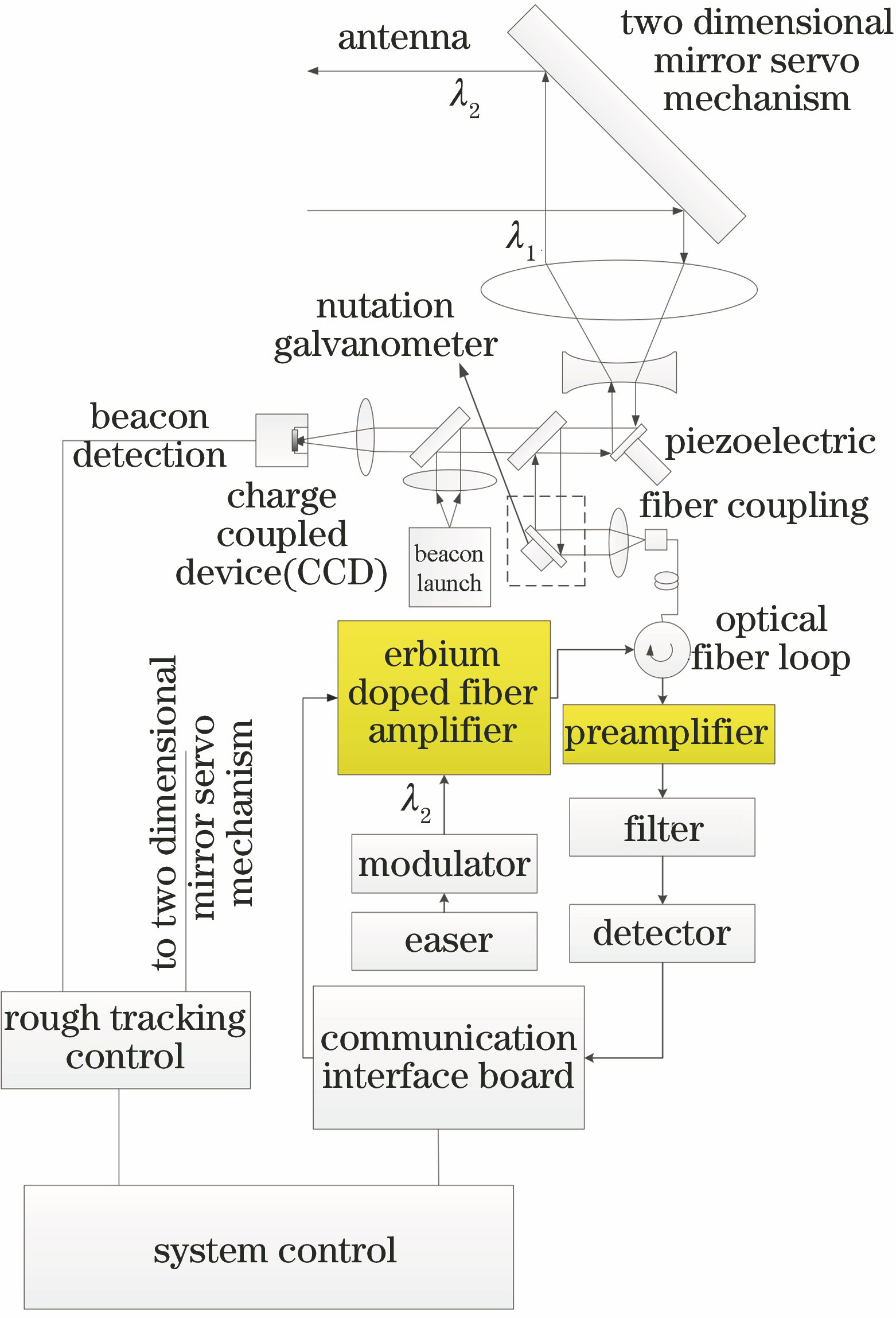
Fig. 1. Network topology of space laser communication network
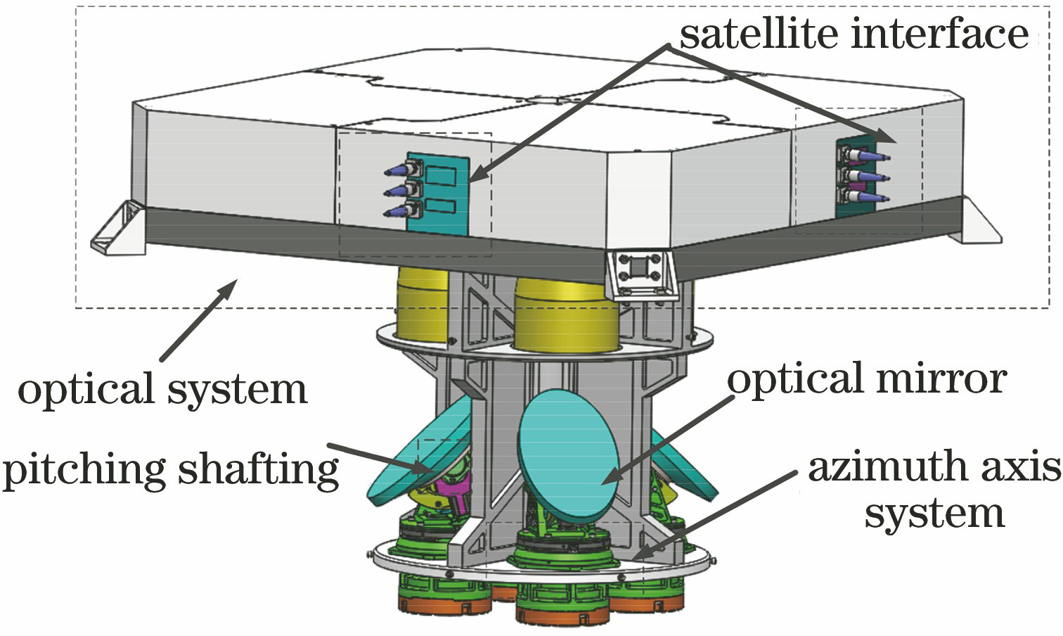
Fig. 2. Structure of optical transceiver system
Fig. 3. Structure of main optical transceiver
Fig. 4. Structure of slave optical transceiver
Fig. 5. Overall control scheme of slave optical transceiver
Fig. 6. Strapdown stability control principle
Fig. 7. Strapdown system control scheme
Fig. 8. Frequency characteristic experiment of azimuth axis from slave optical transceiver
Fig. 9. Frequency characteristic test of azimuth axis. (a) Amplitude frequency characteristic curve; (b) phase frequency characteristic curve
Fig. 10. Frequency characteristic identification of azimuth axis. (a) Amplitude frequency identification curve; (b) phase frequency identification curve
Fig. 11. Structure of tracking differentiator (TD)
Fig. 12. Tracking error of PD control under differential velocity measurement
Fig. 13. Tracking error of PD control with nonlinear tracking differentiator
Fig. 14. Bode diagram of tracking system. (a) Amplitude frequency characteristics; (b) phase frequency characteristics
Fig. 15. Hardware composition of airborne photoelectric pod in slave optical transceiver
Fig. 16. Experiment on coarse tracking control of slave optical transceiver in network
Fig. 17. Azimuth axis tracking error under differential velocity measurement
Fig. 18. Azimuth axis tracking error in differential velocimetry

Set citation alerts for the article
Please enter your email address
© Copyright 2018-2021 | Chinese Laser Press. All Rights Reserved 沪ICP备15018463号-20