• Laser & Optoelectronics Progress
  • Vol. 55, Issue 6, 061405 (2018)
Xiao Wu*
Author Affiliations
  • School of Science and Technology, Zhejiang International Studies University, Hangzhou, Zhejiang 310021, China
  • show less
    DOI: 10.3788/LOP55.061405 Cite this Article Set citation alerts
    Xiao Wu. Influence of Interference Deviation on Four-Beam Interference with Circular Polarization[J]. Laser & Optoelectronics Progress, 2018, 55(6): 061405 Copy Citation Text show less
    (a) Interference beam in rectangular coordinate system; (b) diagram of four beams (B1, B2, B3, B4) interference
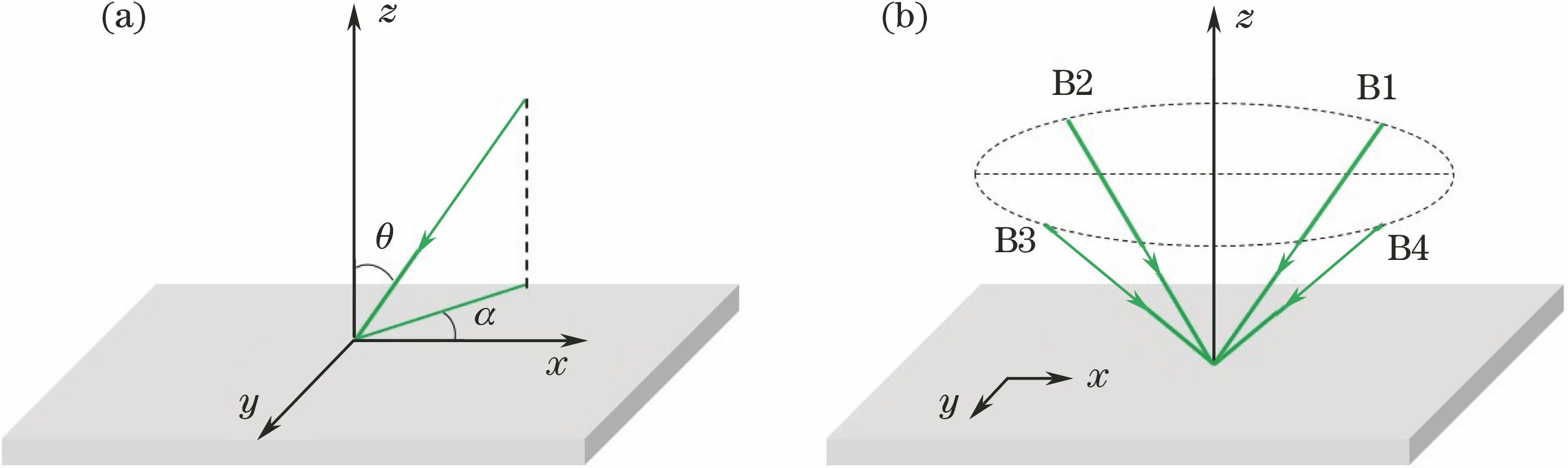
    Fig. 1. (a) Interference beam in rectangular coordinate system; (b) diagram of four beams (B1, B2, B3, B4) interference
    Interference intensity distributions of four symmetrical RC interference beams using MATLAB simulation. (a) 3-dimensional view of intensity distribution; (b) intensity distribution in xy-plane with the incidence angle θ=10° ; (c) intensity distribution in xy-plane with the incidence angle θ=15°
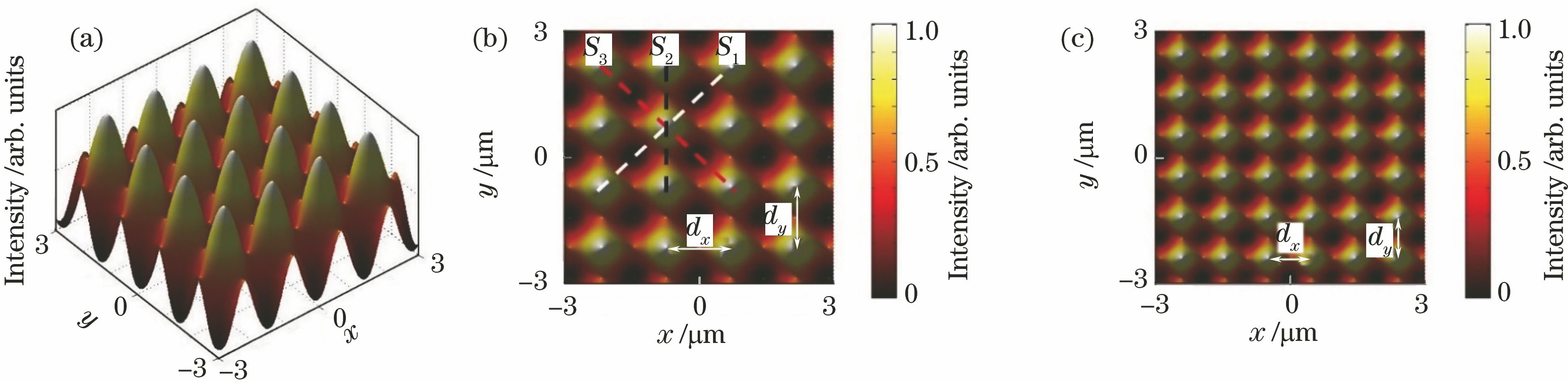
    Fig. 2. Interference intensity distributions of four symmetrical RC interference beams using MATLAB simulation. (a) 3-dimensional view of intensity distribution; (b) intensity distribution in xy-plane with the incidence angle θ=10° ; (c) intensity distribution in xy-plane with the incidence angle θ=15°
    Interference intensity distributions along the xz-axis and yz-axis. (a1)(a2) Symmetrical distribution; (b1)(b2) under incidence deviation; (c1)(c2) under azimuth deviation
    Fig. 3. Interference intensity distributions along the xz-axis and yz-axis. (a1)(a2) Symmetrical distribution; (b1)(b2) under incidence deviation; (c1)(c2) under azimuth deviation
    Interference intensity distributions. (a) Under azimuth deviation; (b) under azimuth deviation; (c) under both incidence and azimuth deviations
    Fig. 4. Interference intensity distributions. (a) Under azimuth deviation; (b) under azimuth deviation; (c) under both incidence and azimuth deviations
    Parameterl=1l=2l=3
    SlS1=-sinθ1cosα1sinθ1sinα1-sinθS2=-sinθ1cosα1+sinθsinθ1sinα1S3=-1
    dxldx1=λsinθ1cosα1dx2=λsinθ1cosα1+sinθdx3=λsinθ
    dyldy1=λsinθ1sinα1-sinθdy2=λsinθ1sinα1dy3=λsinθ
    dzdz=λcosθ1-cosθ
    Table 1. Slope of lines and interference periods where the maximum interference intensity appears
    ParameterDeviation of incident angleDeviation of azimuth angle
    SlS1=sinθ1sinθ,S2=¥,S3=-1S1=-cosα1sinα1-1,S2=-cosα1+1sinα1,S3=-1
    dxldx1=λsinθ1,dx2=λsinθ+sinθ1,dx3=λsinθdx1=λsinθcosα1,dx2=λsinθ(cosα1+1),dx3=λsinθ
    dyldy1=λsinθ,dy2=¥,dy3=λsinθdy1=λsinθ(1-sinα1),dy2=λsinα1sinθ,dy3=λsinθ
    dzdz=λcosθ1-cosθdz
    Table 2. Slope of lines and interference periods when there is a deviation in the incident angle or azimuth angle
    Xiao Wu. Influence of Interference Deviation on Four-Beam Interference with Circular Polarization[J]. Laser & Optoelectronics Progress, 2018, 55(6): 061405
    Download Citation