
Nanning Yi, Rong Zong, Rongrong Qian, Tao Duan. Graphene-Based Dual-Function Switchable Broadband Terahertz Polarization Converter[J]. Laser & Optoelectronics Progress, 2021, 58(23): 2323001
- Laser & Optoelectronics Progress
- Vol. 58, Issue 23, 2323001 (2021)
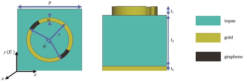
Fig. 1. Schematic diagram of the metasurface structure of mixed graphene-metal. (a) Top view; (b) side view
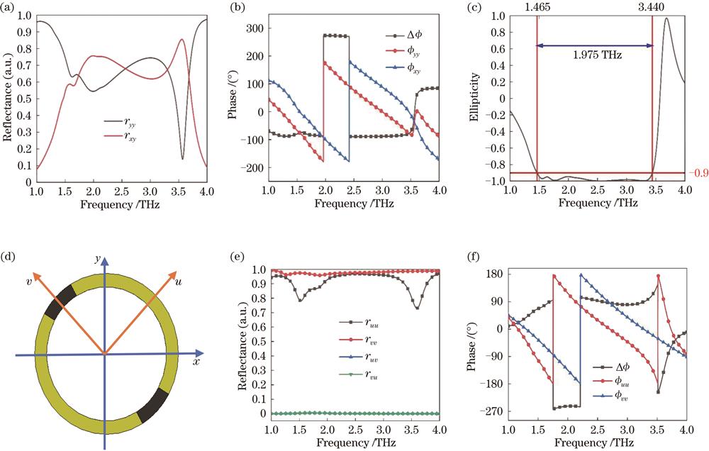
Fig. 2. When the Fermi level of graphene is fixed at 0 for the proposed metamaterial, (a) simulated spectra of the co-polarization and cross-polarization reflection amplitudes under normally incident wave with y-polarization. (b) Phase and phase difference corresponding to reflection coefficient (c) spectra of ellipticity. (d) Schematic diagram of the exploded view of the incident wave electric field. When working under vertically incident u and v polarized terahertz waves, the simulated spectrum of (e) reflection amplitude and (f) spectra of phase.
Fig. 3. When the Fermi level of graphene is fixed at 1 eV for the proposed metamaterial, (a) simulated spectra of the co-polarization and cross-polarization reflection amplitudes under normally incident wave with y-polarization. When working under vertically incident u and v polarized terahertz waves, the simulated spectrum of (b) and (c) reflection amplitude and (d) phase.
Fig. 4. When the Fermi level of graphene is fixed at 0 and the relaxation time is fixed at 1 ps, the values are (a) (b) 1.708 THz, (c),(d) 2.582 THz and (e), (f) 3.277 THz The surface current distribution on the top layer resonant ring (1st and 3rd column) and the bottom gold film (2nd and 4th column). (a), (c), and (e) show those for the u-polarized incident wave, and (b),(d),(f) show those for the v-polarized incident wave. The black arrow in the figure indicates the dominant current direction.
Fig. 5. Electric field distribution at resonance frequency points (a) 1.708 THz, (b) 2.582 THz and (c) 3.277 THz when the metasurface behaved as QWP
Fig. 6. When the Fermi level of graphene is fixed at 1 eV and the relaxation time is fixed at 1 ps, the values are (a), (b) 1.58 THz, (c),(d) 2.344 THz and (e), (f) 3.333 THz. The surface current distribution on the top layer resonant ring (1st and 3rd column) and the bottom gold film (2nd and 4th column). (a), (c) and (e) indicate that the u-polarized wave is incident on the surface of the metamaterial vertically, and (b),(d),(f) indicates that the v-polarized wave is incident on the surface of the metamaterial. The black arrow in the figure indicates the dominant current direction.
Fig. 7. Electric field distribution at resonance frequency points (a) 1.58 THz, (b) 2.344 THz and (c) 3.333THz when the metasurface behaved as HWP
Fig. 8. When the metasurface is used as QWP (a) the influence of different dielectric layer thicknesses on ellipticity, (b) influence of different resonance ring radius on ellipticity and when it is used as HWP (c), influence of different dielectric layer thicknesses on PCR (d), the influence of different resonant ring radius on PCR.
Fig. 9. Spectra of the proposed hypersurface PCR with frequency changes under different graphene Fermi levels
Fig. 10. When the metasurface proposed behaved as a QWP, (a) spectrum of the ellipticity change with the incident angle during TE polarization (b) spectrum of the ellipticity change with incident angle during TM polarization.and when the metasurface behaved as a HWP, (c) spectrum of PCR with the angle of incidence during TE polarization, (d) spectrum of the PCR with angle of incidence during TM polarization. The black and white dash lines in the figure indicated efficient polarization conversion bandwidth(

Set citation alerts for the article
Please enter your email address
© Copyright 2018-2021 | Chinese Laser Press. All Rights Reserved 沪ICP备15018463号-20