• Laser & Optoelectronics Progress
  • Vol. 59, Issue 10, 1011003 (2022)
Kun Gao1、2、**, Jiangtao Xu1、2, and Zhiyuan Gao1、2、*
Author Affiliations
  • 1School of Microelectronics, Tianjin University, Tianjin 300072, China
  • 2Tianjin Key Laboratory of Imaging and Sensing Microelectronics Technology, Tianjin , 300072, China
  • show less
    DOI: 10.3788/LOP202259.1011003 Cite this Article Set citation alerts
    Kun Gao, Jiangtao Xu, Zhiyuan Gao. Noise and Error Analyses of a Pulse Sequence Image Sensor[J]. Laser & Optoelectronics Progress, 2022, 59(10): 1011003 Copy Citation Text show less
    Pixel structure of pulse sequence image sensor
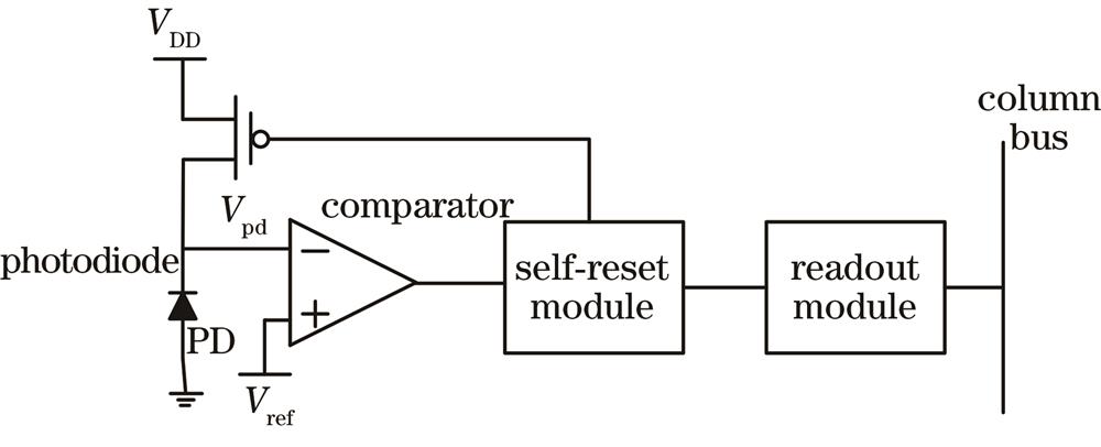
    Fig. 1. Pixel structure of pulse sequence image sensor
    Relationship between trigger time, readout time, and pulse interval
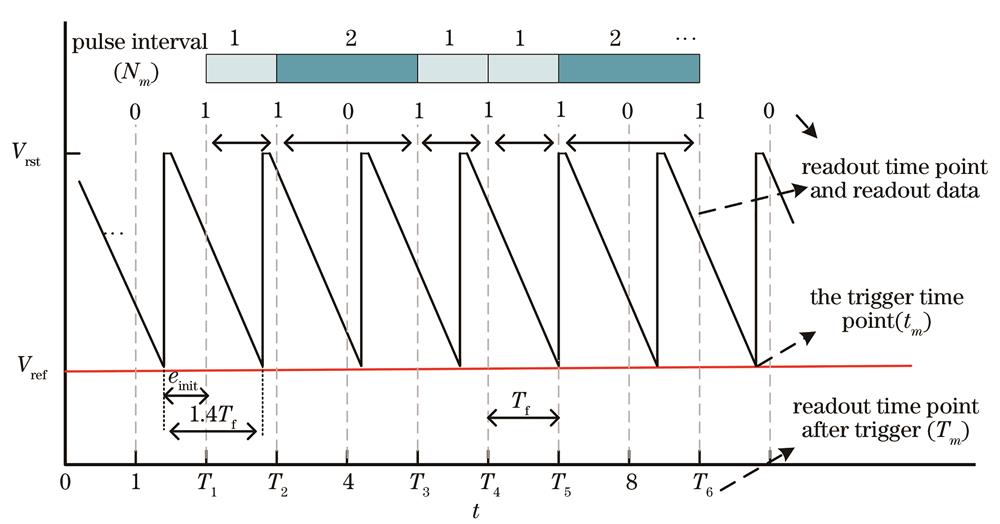
    Fig. 2. Relationship between trigger time, readout time, and pulse interval
    Characteristic curve of pulse interval and reconstructed gray scale
    Fig. 3. Characteristic curve of pulse interval and reconstructed gray scale
    Images under the influence of different noises. (a) Image affected by spatial noise; (b) images affected by temporal noise and single-code flicker noise; (c) 50th frame and 100th frame grayscale images reconstructed under same input bar chart
    Fig. 4. Images under the influence of different noises. (a) Image affected by spatial noise; (b) images affected by temporal noise and single-code flicker noise; (c) 50th frame and 100th frame grayscale images reconstructed under same input bar chart
    Time error rate corresponding to spatial noise varies with Vdiff and Ip. (a) Relationship between time error and Vdiff; (b) relationship between time error and Ip
    Fig. 5. Time error rate corresponding to spatial noise varies with Vdiff and Ip. (a) Relationship between time error and Vdiff; (b) relationship between time error and Ip
    Relationship between error caused by temporal noise and Vdiff、Cpd
    Fig. 6. Relationship between error caused by temporal noise and VdiffCpd
    Relationship between light intensity and relative error under synchronous readout mechanism. (a) Vdiff=2 V;(b) Vdiff=1.5 V
    Fig. 7. Relationship between light intensity and relative error under synchronous readout mechanism. (a) Vdiff=2 V;(b) Vdiff=1.5 V
    Under different Vdiff, FPN and temporal noise change with photocurrent. (a) FPN changes with photocurrent; (b) temporal noise changes with photocurrent
    Fig. 8. Under different Vdiff, FPN and temporal noise change with photocurrent. (a) FPN changes with photocurrent; (b) temporal noise changes with photocurrent
    Images taken by the sensor. (a) 500 lx uniform light; (b) moment the bullet was fired
    Fig. 9. Images taken by the sensor. (a) 500 lx uniform light; (b) moment the bullet was fired
    Under different Vdiff, FPN and temporal noise change with light intensity. (a) FPN changes with light intensity; (b) temporal noise changes with light intensity
    Fig. 10. Under different Vdiff, FPN and temporal noise change with light intensity. (a) FPN changes with light intensity; (b) temporal noise changes with light intensity
    ParameterValueParameterValue
    Cpd /fF10Vref /V1.0‒3.125
    Id /pA1θc0.005
    Vrst /V3.3Vtal /mV16
    Table 1. Related parameters in the noise model
    ParameterValueParameterValue
    Fabrication process /μm0.11Fill factor /%13.8
    Array size250×400Vref /V1.05-2.45
    Pixel size /(μm×μm)20×20Vrst /V2.4-3.3
    Table 2. Related parameters of the sensor chip
    Kun Gao, Jiangtao Xu, Zhiyuan Gao. Noise and Error Analyses of a Pulse Sequence Image Sensor[J]. Laser & Optoelectronics Progress, 2022, 59(10): 1011003
    Download Citation