
Minshuang Huang, Youwen Xu, Miao Cheng. Atmospheric Pressure and Large Volume Non-Equilibrium Plasma Discharge Technology[J]. Laser & Optoelectronics Progress, 2021, 58(5): 0500007
- Laser & Optoelectronics Progress
- Vol. 58, Issue 5, 0500007 (2021)
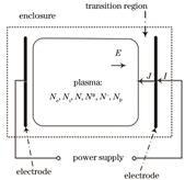
Fig. 1. Schematic of gas discharge generating non-equilibrium plasma
![High-voltage large-volume discharge with limited current density. (a) Array needle cathode discharge with ballast resistance[12];(b) dielectric barrier discharge plasma jet source structure and discharge image[15];(c) capillary plasma pelectrode[16];(d) laser microscopic image of DBD-based plasma display front substrate transformed into CPED structure and laser micrograph of the capillary on the surface of the medium[17]](/richHtml/lop/2021/58/5/0500007/img_2.jpg)
Fig. 2. High-voltage large-volume discharge with limited current density. (a) Array needle cathode discharge with ballast resistance[12];(b) dielectric barrier discharge plasma jet source structure and discharge image[15];(c) capillary plasma pelectrode[16];(d) laser microscopic image of DBD-based plasma display front substrate transformed into CPED structure and laser micrograph of the capillary on the surface of the medium[17]
Fig. 3. Schematic diagram of the discharge device of the plasma cathode. (a) Schematic of the laser discharge device using a plasma electrode in which the relative timing of the volume discharge and the surface discharge can be controlled[19];(b) schematic for the post-acceleration experiment of the plasma cathode discharge electron beam[20];(c) self-breakdown-based single-gap plasma cathode electron gun[21];(d) high current linear aperture radial multichannel pseudospark switch[22];(e) a tapered multi-gap multi-aperture pseudospark-sourced electron gun based X-band slow wave oscillator[23]
Fig. 4. Micro-hollow electrode structure and volt-ampere characteristic curve [7]
Fig. 5. Several representative micro hollow cathode discharge structures[29-33].(a) Micro hollow discharge electrode structure and 2×2 array hollow cathode discharge photos;(b) micro hollow discharge etching silicon substrate device and etched silicon hole SEM photo;(c) micro hollow cathode structure of inverted pyramid and 10×10 array discharge photos;(d) linear array discharge device composed of micro hollow cathode discharge unit
Fig. 6. Capillary micro hollow cathode discharge [35]. (a) Schematic diagram of hollow cathode plasma mini-jet generator and optical test; (b) four-tube circuit with single power supply and ballast resistance;(c) photograph of argon plasma micro-jet discharge when the distance between electrodes is 2 mm
Fig. 7. Glow discharge maintained by micro hollow cathode discharge[7]

Set citation alerts for the article
Please enter your email address
© Copyright 2018-2021 | Chinese Laser Press. All Rights Reserved 沪ICP备15018463号-20