• Laser & Optoelectronics Progress
  • Vol. 57, Issue 23, 232201 (2020)
Rui Yuan, Chunzhu Zhao*, Yu Guo, Yuan Ju, and Mingxu Piao
Author Affiliations
  • School of Opto-Electronic Engineering, Changchun University of Science and Technology, Changchun, Jilin 130022, China
  • show less
    DOI: 10.3788/LOP57.232201 Cite this Article Set citation alerts
    Rui Yuan, Chunzhu Zhao, Yu Guo, Yuan Ju, Mingxu Piao. Design of Airborne Conformal Optical System Based on Computational Imaging[J]. Laser & Optoelectronics Progress, 2020, 57(23): 232201 Copy Citation Text show less
    Schematic of conformal window optical system under different conditions. (a) 0° scan angle in Y-Z plane; (b) 0° scan angle in X-Z plane; (c) 15° scan angle in X-Z plane
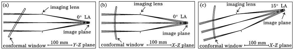
    Fig. 1. Schematic of conformal window optical system under different conditions. (a) 0° scan angle in Y-Z plane; (b) 0° scan angle in X-Z plane; (c) 15° scan angle in X-Z plane
    Variation curves of aberration with LA
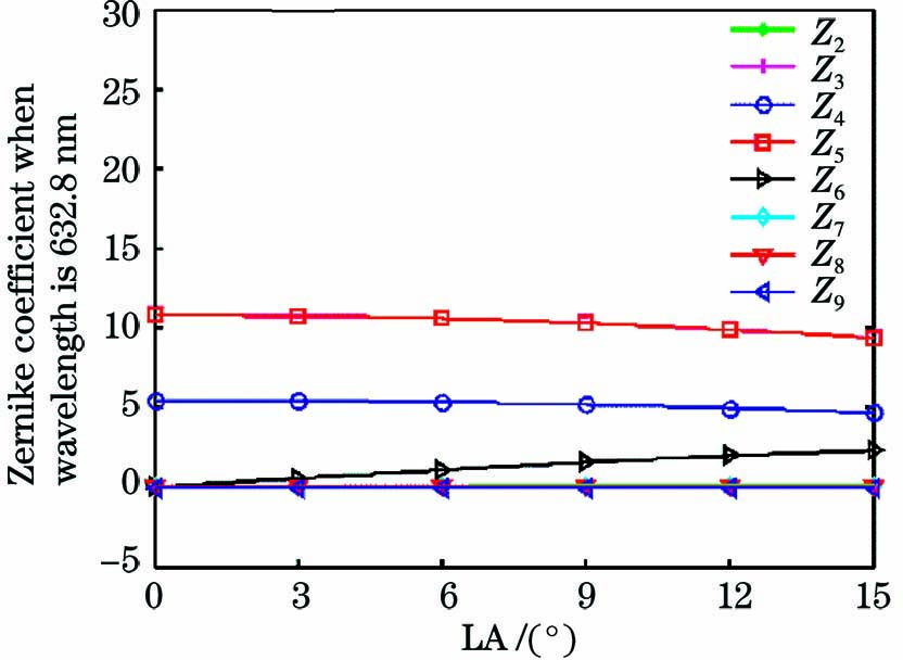
    Fig. 2. Variation curves of aberration with LA
    Flow chart of particle swarm optimization algorithm
    Fig. 3. Flow chart of particle swarm optimization algorithm
    Schematic of wavefront encoding conformal optical system. (a) 0° viewing angle on X-Z plane; (b) 0° viewing angle on Y-Z plane; (c) 15° viewing angle on X-Z plane
    Fig. 4. Schematic of wavefront encoding conformal optical system. (a) 0° viewing angle on X-Z plane; (b) 0° viewing angle on Y-Z plane; (c) 15° viewing angle on X-Z plane
    PSF images before optimization under different scan angles. (a) 0°; (b) 3°; (c) 6°; (d) 9°; (e) 12°; (f) 15°
    Fig. 5. PSF images before optimization under different scan angles. (a) 0°; (b) 3°; (c) 6°; (d) 9°; (e) 12°; (f) 15°
    PSF images after optimization under different scan angles. (a) 0°; (b) 3°; (c) 6°; (d) 9°; (e) 12°; (f) 15°
    Fig. 6. PSF images after optimization under different scan angles. (a) 0°; (b) 3°; (c) 6°; (d) 9°; (e) 12°; (f) 15°
    Simulation results of Lena images under different scan angles. (a) Original image; (b) 0°; (c) 3°; (d) 6°; (e) 9°; (f) 12°; (g) 15°
    Fig. 7. Simulation results of Lena images under different scan angles. (a) Original image; (b) 0°; (c) 3°; (d) 6°; (e) 9°; (f) 12°; (g) 15°
    MTF curves of static correction method under different FOV[13]
    Fig. 8. MTF curves of static correction method under different FOV[13]
    MTF curves of proposed method in each FOV
    Fig. 9. MTF curves of proposed method in each FOV
    ParameterValue
    Focal length/mm200
    F number2.8
    FOV/[(°)×(°)]2.4×1.8
    FOV in X axis/(°)±15
    FOV in Y axis/(°)0
    Wavelength range/nm520-570
    Table 1. Parameters of conformal window optical system
    ParameterOptimized value
    a2.266×10-3
    b-9.496×10⁻³
    Distance/mm48.578
    MMF7×10-3
    Table 2. Parameter optimization results of mask
    Rui Yuan, Chunzhu Zhao, Yu Guo, Yuan Ju, Mingxu Piao. Design of Airborne Conformal Optical System Based on Computational Imaging[J]. Laser & Optoelectronics Progress, 2020, 57(23): 232201
    Download Citation