
Jiqiang Kang, Rui Zhu, Yunxu Sun, Jianan Li, Kenneth K. Y. Wong. Pencil-beam scanning catheter for intracoronary optical coherence tomography[J]. Opto-Electronic Advances, 2022, 5(3): 200050
- Opto-Electronic Advances
- Vol. 5, Issue 3, 200050 (2022)
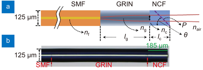
Fig. 1. Schematic diagram of the spacer-removed probe. nf, ng, nc, and nair are the refractive index of SMF core, GRIN fiber at the center, NCF, and air, respectively; lg and lc are the length of GRIN fiber and NCF; P and θ are the polishing surface and tilt angle.
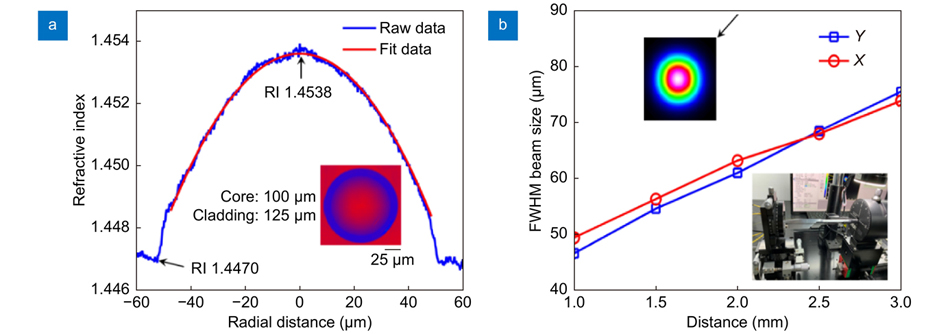
Fig. 2. (a ) Refractive index of the GRIN fiber. Inset: cross section of GRIN fiber captured by the refractive index profiler. (b ) FWHM beam size at different position. Inset: beam profile at 2-mm position (left top); beam measurement setup (right bottom).
Fig. 3. (a ) Working distance and Rayleigh length versus different GRIN fiber length. (b ) Beam size and divergence angle versus different GRIN fiber length.
Fig. 4. (a ) Angle-polished probe. (b ) Distal optics with coil. (c ) Distal image of assembled catheter with a guide wire and radiopaque marker. (d ) Full view of the whole catheter. (e ) Connection of the catheter and PIU. Inset: cap used to house the SC/APC connector. U: UV adhesive; C: double-wrapped torque coil; P: plastic sheath; M: radiopaque marker; G: 0.014-inch guide wire; T: catheter; L: Luer connector.
Fig. 5. Catheter FWHM beam size at different imaging depth. X: horizontal direction, Y: vertical direction. Inset: beam profile at 2-mm position (right bottom); beam size measurement setup (left top).
Fig. 6. (a ) in vivo imaging arrangement. (b ) X-ray image of porcine heart in this experiment. (c ) Cross-section image without stent attachment. (d ) Cross-section image with the stent. (e ) Cutaway view of the 3D image of a segment of coronary artery with stent and guide wire. ECG: electrocardiogram; G: guidewire; H: healthy blood vessel wall; T: catheter; L: small blood vessel branch; S: stent.

Set citation alerts for the article
Please enter your email address
© Copyright 2018-2021 | Chinese Laser Press. All Rights Reserved 沪ICP备15018463号-20