1School of Electronic and Information Engineering, Harbin Institute of Technology (Shenzhen), Shenzhen 518055, China
2International Graduate School at Shenzhen, Tsinghua University, Shenzhen 518055, China
3Shenzhen Vivolight Medical Device & Technology Co., Ltd., Shenzhen 518055, China
4State Key Laboratory of Transient Optics and Photonics, Xi’an Institute of Optics and Precision Mechanics, Chinese Academy of Sciences, Xi’an 710119, China
5Department of Electrical and Electronic Engineering, The University of Hong Kong, Pokfulam Road, Hong Kong, China
6Advanced Biomedical Instrumentation Centre, Hong Kong Science Park, Shatin, New Territories, Hong Kong, China
Current gradient-index (GRIN) lens based proximal-driven intracoronary optical coherence tomography (ICOCT) probes consist of a spacer and a GRIN lens with large gradient constant. This design provides great flexibility to control beam profiles, but the spacer length should be well controlled to obtain desired beam profiles and thus it sets an obstacle in mass catheter fabrication. Besides, although GRIN lens with large gradient constant can provide tight focus spot, it has short depth of focus and fast-expanded beam which leads to poor lateral resolution for deep tissue. In this paper, a type of spacer-removed probe is demonstrated with a small gradient constant GRIN lens. This design simplifies the fabrication process and is suitable for mass production. The output beam of the catheter is a narrow nearly collimated light beam, referred to as pencil beam here. The full width at half maximum beam size varies from 35.1 μm to 75.3 μm in air over 3-mm range. Probe design principles are elaborated with probe/catheter fabrication and performance test. The in vivo imaging of the catheter was verified by a clinical ICOCT system. Those results prove that this novel pencil-beam scanning catheter is potentially a good choice for ICOCT systems.
Introduction
Intracoronary optical coherence tomography (ICOCT) is a specific application of optical coherence tomography (OCT) technology1-6. Benefiting from its high axial resolution (~10 µm), large imaging depth (>2 mm), and video-rate imaging speed, ICOCT becomes more and more popular in percutaneous coronary intervention (PCI) surgery7-10. Similar to the function of intravascular ultrasound (IVUS), ICOCT is normally applied to assess the intravascular plaque portrait before stent implantation and to evaluate stent attachment after the surgery.
Since most of the lesions locate deeply inside human body and typically happen at small blood vessel with diameter of ~2 mm (human coronary arteries for an instance), ICOCT has unique system structures. The major difference between ICOCT with other OCT implementations is the light scanning device. Different from ophthalmology OCT where galvanometer or MEMS scanning mirrors are generally used, a type of meters long soft imaging catheter is a standard configuration for ICOCT11-14. The probe inside imaging catheter is rotated and pulled back to get three-dimensional (3D) images of an artery lumen. Currently, most of the ICOCT imaging catheters are side-viewing, and there are two subcategories, i.e. distal-driven and proximal-driven catheters. Distal-driven catheter relies on a ~1-mm diameter micro-motor with several thousand revolutions per second (rps) rotation speed, while proximal-driven catheter uses much smaller driveshaft with diameter of about 0.5 mm to transmit torque from proximal end to distal end13-18. Since the optical probes in proximal-driven catheters are normally all-fiber based and they are easy to manufacture at low cost compared with micro-motors, disposable proximal-end driven catheters are the workhorses in current PCI surgery.
Optical probe is the key component in proximal-driven catheter. The probe consists of meters of single-mode fiber (SMF) to guide near infrared light at 1310-nm band in general and a distal focusing optics to focus the light beam onto lesions as well as to collect back-reflected photons. Working distance, depth of focus, and spot size are three vital parameters to evaluate the performance of probes. Some novel micro lenses and designs are developed to extend working distance, enlarge depth of focus, and minimize spot size19-27. Although new technologies develop rapidly, most current ICOCT catheters implement ball lens or gradient index (GRIN) lens. Ball lens catheter has simple architecture and it avoids chromatic aberration intrinsically which makes it quite promising at shorter working wavelength like 800-nm band20. Different from ball lens scheme, GRIN lens design adopts GRIN fiber to focus light beam.
In current mainstream GRIN lens probe, a glass rod spacer is set before a GRIN lens to expand light beam for desired beam profile28-34. This design provides great flexibility to control beam profile. However, it has several shortcomings. Firstly, the length of the glass rod spacer with several hundred micrometers is crucial and should be well controlled which is difficult to manipulate in practice. Secondly, since the light beam is expanded before GRIN lens, it is hard to fabricate small size catheters by a small GRIN lens. A large size GRIN lens is hard to be fusion spliced directly with conventional SMF and UV curing might be applied. UV curing needs well alignment and back-reflection might be strong. Thirdly, conventional probe always has a large gradient constant (large-g, g>2 mm–1) GRIN lens to provide a stronger focus ability. Stronger focus ability can focus the light beam in a small spot but will diverge the light beam quickly with a short depth of focus. The quickly diverged light beam lower the lateral resolution especially for deep tissue. Finally, a focused light beam brings high back reflection power easily when the probe scans the metal stent surface. High back-reflection power saturates the photodetector and generates artifacts in images. Indeed, the focused light beam can be replaced by a narrow nearly collimated light beam which is generally referred to as pencil beam35, and the spacer plus large-g GRIN lens combination can be optimized by the scheme of only using a low gradient constant (low-g) GRIN lens. Reed et al. reported the application of this scheme where a variety of GRIN lenses with g varying from 2 to 4 mm–1 were fabricated to make probes and a probe was successfully used to measure rats brain motion29.
In this paper, we further prove the effectiveness of this spacer-removed scheme and extend its application to intracoronary imaging applications. In detail, a type of all-fiber probe for proximal-driven ICOCT catheter is demonstrated with a g=1.8 mm–1 GRIN lens which was spliced directly with the SMF and no glass rod spacer was incorporated. The GRIN lens has 1/4 pitch and the output beam is pencil beam, i.e. no focus point. The pencil beam has 0.8 degree full divergence angle, and the full width at half maximum (FWHM) beam size varies from 35.1 µm to 75.3 µm in air over 3-mm imaging range. Probe design principles and probe/catheter fabrication as well as test results are elaborated in Probe design and realization and Catheter fabrication and performance test, respectively. The in vivo imaging capability of the catheter is verified by a clinical ICOCT system with a stent-implanted beating porcine heart as the sample as demonstrated in In vivo porcine intracoronary imaging.
Probe design and realization
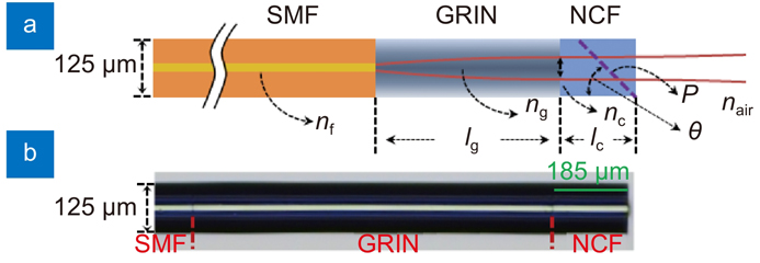
Figure 1 depicts the schematic diagram of the spacer-removed probe. The GRIN lens was fusion spliced directly with ~1.6-m SMF, and 185-µm long no-core fiber (NCF) was fusion spliced with the GRIN lens. NCF provides a polishing basement to make a reflection surface at the tip of the probe for light beam redirection.
Figure 1.Schematic diagram of the spacer-removed probe.nf, ng, nc, and nair are the refractive index of SMF core, GRIN fiber at the center, NCF, and air, respectively; lg and lc are the length of GRIN fiber and NCF; P and θ are the polishing surface and tilt angle.
The output beam parameters after the NCF can be quantified by ABCD metrics. The working distance (Zw) and beam waist (ws) of the output beam can be calculated by31
where w0 is the beam radius of the SMF; a0=λ/(πw02) and λ is working wavelength; g is the gradient constant of the GRIN lens.
Since the output beam can be treated as Gaussian beam, the Rayleigh length (zR) is determined by zR= πws2/λ in air. According to Gaussian beam transmission law, the beam radius at z position away from the beam waist is determined by w(z)=ws(1+(z/zR)2)1/2. Therefore, the beam divergence angle at position z can be calculated by θ=2arctan(FWHM((w(z)-ws))/z) in radians.
A type of customized GRIN fiber was used to fabricate this low-NA spacer-removed probe. The refractive-index profile (RIP) of this GRIN fiber was measured by a refractive index profiler (S14, Photon Kinetics, Inc) as shown in Fig. 2(a). The refractive index at the center of the GRIN fiber isng=1.4538 and it is 1.4470 for the cladding. The NAof the GRIN fiber can thus be calculated as NA≈0.14. The GRIN fiber has parabolic radial RIP and can be described by the formula of n(r)=ng(1–g2r2/2). From the measured RIP, the calculated gradient constant g is 1.8 mm–1 and the pitch of the GRIN fiber is P=2π/g=3.49 mm. This is the smallest g that has even been reported to fabricate ICOCT probes to the best of our knowledge. Low g GRIN fiber paves the way for low NA probe with large imaging depth and applicable beam size.
Figure 2.(a) Refractive index of the GRIN fiber. Inset: cross section of GRIN fiber captured by the refractive index profiler. (b) FWHM beam size at different position. Inset: beam profile at 2-mm position (left top); beam measurement setup (right bottom).
By taking the values of refractive index ng and gradient constant g into Eq. (1) and Eq. (2), the working distance, Rayleigh length, and beam size at waist versus different GRIN fiber length can be calculated, as shown in Fig. 3(a) and 3(b). From Fig. 3(a), the maximum Rayleigh length is 3 mm when the GRIN fiber length is 0.87 mm, i.e. 1/4 pitch of the GRIN fiber. At 1/4 pitch length, the calculated beam waist diameter is 70 µm corresponding to FWHM of 41.2 µm in air and the FWHM of the beam at 1 mm and 3 mm position are 44.0 µm and 58.3 µm. The working distance is –0.12 mm which means the beam waist locates inside the NCF. Different from conventional spacer-included probe where depth of focus is twice of the Rayleigh length, single Rayleigh length is long enough for the spacer-removed probe to support 3-mm imaging range. Moreover, when the GRIN fiber length is slightly increased to 0.9 mm, i.e. the cross point of the red and blue curve in Fig. 3(a), the imaging range can be further extended to 3.49 mm because the working distance is 0.89 mm and Rayleigh length is 2.60 mm at this point. The full beam divergence angle at z=3 mm position versus different GRIN fiber length is also shown in Fig. 3(b) in red. The theoretical minimum divergence angle is 0.7 degree when GRIN fiber length is 0.87 mm and it is 0.9 degree when the GRIN fiber length is 0.9 mm. These beam parameters show great potential of this probe for ICOCT applications.
Figure 3.(a) Working distance and Rayleigh length versus different GRIN fiber length. (b) Beam size and divergence angle versus different GRIN fiber length.
Since 3-mm is long enough for ICOCT application and a smaller divergence angle is important to achieve balanced lateral resolution within the whole imaging range, 1/4 pitch GRIN fiber was used to fabricate the probe which is shown in Fig. 1(b). The 0.87-mm GRIN fiber and 0.185-mm NCF (FG105LCA, Thorlabs, USA) were cleaved under a stereo microscope for high precision cleaving. The output beam profile of the probe was measured by a scanning slit beam analyzer (BP209-IR/M, Thorlabs, USA), and a 1310-nm continuous wave (CW) light source (S1FC1310, Thorlabs, USA) was used. For the beam analyzer, a fixed 0.93-mm gap (dead zone) exists between the sample surface and the scanning slit. The gap was calibrated by measuring the output beam profile of a standard SMF. Since the NCF length is 0.185 mm and the working distance of the probe is −0.12 mm, the minimum measurable distance between the probe’s beam waist and the scanning slit was about 1 mm considering the 0.93-mm gap. During the measurement, the output surface of the NCF coincided with the sample surface of the beam analyzer and a translation stage was used to move the probe with 0.5-mm step size. The measured FWHM beam size versus distance away from the beam waist is shown in Fig. 2(b). Here, the beam sizes at horizontal (X) and vertical (Y) direction have minor differences, and the reason for the differences may be because of the imperfect cleaved NCF output surface which distorted the output beam profile in some degree. The average FWHM beam size at 1-mm position is 48.0 µm and it is 74.7 µm at 3-mm position in air corresponding to 0.8-degree full divergence angle. Although the GRIN fiber and NCF were cleaved under microscope, length deviation is hard to be eliminated. Considering the fiber length deviation, the experimental results match the theoretical predictions.
Catheter fabrication and performance test
The probe was polished 40-degree angle at the NCF to deflect the light beam for side-viewing. The polished probe is shown in Fig. 4(a). This non-45-degree angle design aims to diminish the specular reflection from the sheath and sample surfaces. After polishing, the probe was enclosed into a double-wrapped torque coil (Fort Wayne Metals, USA) which was used to uniformly transfer torque from proximal to distal end during rotation and to linearly translate the probe. The probe and the coil were bonded together by UV adhesive, and a piece of heat-shrink tubing was used to protect the polished facet and enclose some air at the same time for total internal reflection. The distal optics is shown in Fig. 4(b). The rigid length of the probe is 2 mm which is the length of the cured glue. To isolate the rotary probe from body fluids and to spin the catheter for circumferential cross-sectional imaging, a 0.86 mm diameter plastic sheath with a transparent imaging window at the distal end was used to encase the torque coil and distal optics as shown in Fig. 4(c). A radiopaque marker was embedded for catheter tracing inside blood vessels with the help of X-ray imaging system and the catheter was specially designed to be guided by a standard 0.014-inch guide wire in PCI surgery.
Figure 4.(a) Angle-polished probe. (b) Distal optics with coil. (c) Distal image of assembled catheter with a guide wire and radiopaque marker. (d) Full view of the whole catheter. (e) Connection of the catheter and PIU. Inset: cap used to house the SC/APC connector. U: UV adhesive; C: double-wrapped torque coil; P: plastic sheath; M: radiopaque marker; G: 0.014-inch guide wire; T: catheter; L: Luer connector.
The full view of the catheter is shown in Fig. 4(d). A SC/APC connector was fabricated at the proximal end of the catheter and the connector was housed into a customized cap for automated connection with the patient interface unit (PIU) as shown in Fig. 4(e). A high-speed fiber optical rotary joint and a push/pull motor were included in the PIU which are not shown in Fig. 4(e) for limited space. A nickel titanium tube was used to link the cap and the torque coil and was housed inside a segment of black plastic tube. A Luer connector was made for catheter flushing with contrast agent in clinic applications. The total catheter length and optical fiber length are 1670 mm and 1640 mm, respectively. The structures and packages of this type of catheters are well described in references13, 14.
The optical insertion loss of the catheter is 0.8 dB. The beam size at different imaging depth was measured by the same beam analyzer (BP209-IR/M, Thorlabs, USA) in air with a tilt angle to ensure perpendicular incidence of the light beam from the angle-polished probe. During the measurement, the outer surface of the plastic sheath coincided with the sample surface of the beam analyzer, and thus the beam size measuring started at 0.93-mm from the outer surface of the sheath. The catheter was moved by the translation stage with 0.5-mm step size. To prove the large imaging range of the catheter, beam size evolution over 3-mm range were quantified, i.e. 0.93-mm to 3.93 mm starting from the outer surface of the sheath and it is 1.36 mm to 4.36 mm starting from the center of NCF considering 0.43-mm radius of the catheter. The measured FWHM beam size versus distance is shown in Fig. 5. Here, the beam at horizontal direction (X) and vertical (Y) direction were focused to some degree after polishing and adding the heat-shrink tubing, UV adhesive, and plastic sheath. Moreover, the beam at Y direction diverged faster than the X direction because of the cylindrical surface of the fiber and cured UV glue. The measured average FWHM beam size at 0.93-mm position away from the sheath is 35.1 µm and it is 75.3 µm at 3.93-mm position. The measured full divergence angle in air is 0.8 degree. It is worthy noting that the astigmatism caused by cylindrical surfaces can be further compensated by a cylindrical mirror or a soft lithography window 24, 36.
Figure 5.Catheter FWHM beam size at different imaging depth.X: horizontal direction, Y: vertical direction. Inset: beam profile at 2-mm position (right bottom); beam size measurement setup (left top).
A healthy 4-month-old domestic porcine was anesthetized first for the in vivo intracoronary imaging as shown in Fig. 6(a). The animal experiment protocol was approved by the Institutional Animal Care and Use Committee (IACUC) of Shenzhen Advanced Animal Study Service Center. Before in vivo ICOCT imaging, a 2.75-mm × 12-mm stent (MicroPort Scientific Corporation, Shanghai, China) was implanted within the distal left circumflex artery (LCX) of the porcine. During the imaging process, a 0.014-inch guidewire (Medtronic plc, USA) was inserted into the LCX with the help of an X-ray machine and contrast agent as shown in Fig. 6(b). The ICOCT catheter mentioned above was advanced by the guidewire and moored in the stent area for following OCT imaging. A respiratory support system was used to keep the swine in good living conditions.
Figure 6.(a) in vivo imaging arrangement. (b) X-ray image of porcine heart in this experiment. (c) Cross-section image without stent attachment. (d) Cross-section image with the stent. (e) Cutaway view of the 3D image of a segment of coronary artery with stent and guide wire. ECG: electrocardiogram; G: guidewire; H: healthy blood vessel wall; T: catheter; L: small blood vessel branch; S: stent.
The in vivo porcine intracoronary imaging was conducted with the second-generation clinical P60TM imaging system (Vivolight Medical Device & Technology Co., Ltd., Shenzhen, China). The system works at 1310 nm optical wavelength regime with 11-µm axial resolution in air (7.9-µm in tissue). The A-scan rate of the system is 100 kHz (1024 samples per A-line) and 2048 A-lines per one B-scan. The output power after the catheter was about 10 mW and the imaging sensitivity of the system is 102 dB. The PIU can drive the catheter at maximum 200 rps rotation speed and pull back the catheter of a maximum 60-mm distance within 3 seconds for blood vessel lumen imaging.
In this proof of concept experiment, imaging data were recorded directly from the clinical ICOCT system without post processing. During imaging, the blood vessel lumen was flushed and fulfilled with contrast agent to remove blood to diminish scattering. The intracoronary images captured by this spacer-removed no-focus catheter are shown in Fig. 6(c–e). Fig. 6(c) and 6(d) are the cross-section images of the blood vessel without and with stent attachment, respectively. Here, the healthy blood vessel wall and small blood vessel branch can be clearly visualized, and the stent can be distinguished with the blood vessel wall easily as well. From these images, the lumen diameter was about 2.7 mm, and the imaging depth in tissue was about 1 mm. When the catheter occasionally locates at one edge of the lumen (edge A in Fig. 6(c) for an instance), only a pencil-beam catheter without a focusing point maintains high resolution at the opposite edge of the lumen (edge B in Fig. 6(c) for an instance) because the beam is not severely diverged over the whole imaging range. This feature is hard to achieve by a probe with a focus point because the beam will be diverged fast in this case. 300 2D images were stacked to generate a 3D image of the coronary lumen and the cutaway view of the 3D image is shown in Fig. 6(e). Here, the stent and guide wire were rendered by OpenGL graphical APIs. The white, yellow, and red color labelled in the stent represent the distance between the stent and blood vessel wall (white: less than 200 µm; yellow: 200 µm to 400 µm; red: larger than 400 µm). Thesein vivo porcine intracoronary imaging results prove the effectiveness of this type of catheter for high quality intracoronary imaging applications.
Conclusions
In summary, a type of novel spacer-removed probe for ICOCT catheter is demonstrated, and a full-featured ICOCT catheter was assembled based on this probe. The output beam of the catheter is pencil beam, i.e. no focus spot. The imaging capability of the catheter was tested in a clinical ICOCT system with a stent-implanted beating porcine heart as the sample. The FWHM beam size of the catheter ranges from 35.1 µm to 75.3 µm over 3 mm imaging range. Although the beam size of this catheter is slightly larger than conventional catheters, it has much larger depth of focus with small divergence angle, which makes it has uniform beam profile within the whole imaging range. Moreover, since there is no focus spot, the back-reflection power from strong reflective surfaces, say metal stent surfaces, is minimized which diminishes the possibility of photodetector saturation and avoids artifacts in images consequently. In addition, the fabrication process can be simplified since the spacer is removed which benefits mass production in practice.
[10] Regar E, van Leeuwen AMGJ, Serruys PW. Optical Coherence Tomography in Cardiovascular Research (Informa Healthcare, London, 2007).
[11] Schuman JS, Puliafito CA, Fujimoto JG, Duker JS. Optical Coherence Tomography of Ocular Diseases 3rd ed (Slack Incorporated, Thorofare, 2012).
[18] Swanson E, Petersen CL, McNamara E, Lamport RB, Kelly DL. Ultra-small optical probes, imaging optics, and methods for using same. United States Patent: 6445939, September 3, 2002.
[28] Tearney GJ. Optical biopsy of in vivo tissue using optical coherence tomography (Massachusetts Institute of Technology, Cambridge, 1997).
[35] Wang LV, Wu HI. Biomedical Optics: Principles and Imaging (Wiley-Interscience, Hoboken, 2007).