
Guoqiang Li, Runze Lin, Haichao Guo, Pengfei Tian, Nan Chi, "Visible light communication system at 3.59 Gbit/s based on c-plane green micro-LED," Chin. Opt. Lett. 20, 110602 (2022)
- Chinese Optics Letters
- Vol. 20, Issue 11, 110602 (2022)
Abstract
1. Introduction
Visible light communication (VLC), as a new type of communication technology, has the characteristics of no electromagnetic radiation, being license-free, and high security compared with traditional radio frequency (RF) communication[
Compared with the widely reported blue micro-LED, the “green gap” problem caused by the high In composition of multiple quantum wells (MQWs) has always hindered the realization of high-performance GaN-based green micro-LEDs[
In this work, we measured the performance of green micro-LEDs with different sizes based on the commercial c-plane LED epitaxial wafer in detail and analyzed the VLC performance of such devices at different working conditions by combining the bit loading discrete multi-tone (DMT) modulation format and digital pre-equalization technology. Finally, a 100 µm micro-LED was used to achieve a maximum data rate of 3.59 Gbit/s. The realization of such a high-performance VLC system does not require a complex epitaxial structure design. It is expected that such devices can have broad application prospects in different fields such as Internet of Things and smart lighting.
Sign up for Chinese Optics Letters TOC. Get the latest issue of Chinese Optics Letters delivered right to you!Sign up now
2. Performance of Micro-LEDs
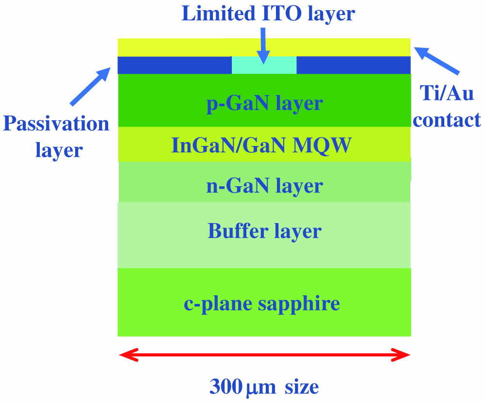
Figure 1 shows the structure of the green micro-LED, which includes a sapphire substrate, a buffer layer, an n-type GaN layer, a MQW layer, a p-type GaN layer, and a limited current spreading layer (indium tin oxide, ITO). The fabrication process has been reported in detail in our previous work[
![]()
Figure 1.Schematic structure of multi-functional green micro-LED.
Figures 2(a) and 2(b) are the current-voltage (I-V) curves and the light output power-current (P-I) curves of micro-LEDs with different sizes (80, 100, and 150 µm, referring to the sizes of ITO layers), respectively. In order to prevent irreversible damage due to the excessively high operating current, the maximum current was limited to the value where the light output power of the device was saturated. It can be seen that as the sizes increase, the maximum operating current and light output power also increase simultaneously, which are 100, 160, 210 mA and 0.848, 1.365, 2.120 mW, respectively. The corresponding maximum current densities are 1562.5, 1600,
![]()
Figure 2.(a) I-V curves and (b) P-I curves of multi-functional green micro-LEDs with different sizes.
In order to further explain the influence of current density on the modulation bandwidth, the frequency response curves of a 100 µm device at different current densities are shown in Fig. 3(a). As the current density ranges from
![]()
Figure 3.(a) Frequency response curves of the 100 µm micro-LED at different current densities. (b) Modulation bandwidth versus current density curves of 80, 100, and 150 µm devices, respectively.
The electroluminescence (EL) spectra have also been tested in detail. Figure 4(a) represents the EL spectra of the 100 µm device at different currents. Figures 4(b) and 4(c) are the peak wavelength and full width at half-maximum (FWHM) curves extracted from the spectra as a function of current density. It can be seen that for the 100 µm micro-LED, the peak wavelength first changes from 523.1 nm (1 mA) to 513.6 nm (90 mA) and then gradually increases to 515.4 nm (160 mA). The blue shift is mainly due to the band filling effect and the suppression of the quantum-confined Stark effect (QCSE) as the carrier density increases[
![]()
Figure 4.EL spectra characteristics of 100 µm micro-LED. (a) Spectra at different currents. (b) Peak wavelength and (c) FWHM versus current curves.
In addition to the change of the peak wavelength, the phenomenon of spectrum broadening will also appear. When the current is 5 mA, the FWHM of the 100 µm device is 33.3 nm. For the maximum current (160 mA), the FWHM of the device is broadened to 44.0 nm, an increase of 32.1%. The most obvious impact of spectral change is the problem of color shift, which is particularly critical in the display application. For the multi-functional device that integrates lighting, display, duplex VLC, and other functions, how to reduce the spectrum shift will be studied in our future research.
3. Experimental Setup and Results
The experimental setup and photograph of the micro-LED-based VLC system are shown in Fig. 5. The bit loading DMT modulation format was utilized to raise spectral efficiency, and it achieved a high data rate. Herein, 122 subcarriers were modulated with DMT modulation. Firstly, the channel estimation was done offline by sending a quadrature phase shift keying (QPSK) training sequence. The channel frequency response obtained from the channel estimation was used for further pre-equalization. The SNR among different DMT subcarriers for bit loading modulation was obtained by calculating the error vector magnitude (EVM) of QPSK symbols[
![]()
Figure 5.Experimental setup of the micro-LED-based VLC system. (a) Photograph of the optical system showing the micro-LED, lens group, and APD. Micrographs of three different sizes of micro-LEDs: (b) 80 µm; (c) 100 µm; (d) 150 µm.
To overcome the bandwidth limitation of the micro-LED, digital pre-equalization was utilized before DMT modulation at the Tx. Based on zero-forcing equalization[
The signal output from the AWG was amplified by an electrical amplifier (EA, Mini-Circuits, ZHL-2-8-S+) and DC-biased with a bias-tee (Mini-Circuits, ZFBT-6GW+). Then, via a high-speed probe, the biased signal was fed into the green micro-LED to finish electro-optical conversion. Micrographs of three different sizes of micro-LEDs are represented in Figs. 5(b)–5(d). In this paper, the transmission performances of these micro-LEDs will be discussed.
By applying a lens group, the optical signal from the micro-LED was collimated and focused on the avalanche photon diode module (APD, Hamamatsu, C5658). The APD was employed to finish photoelectric conversion. The output signal of the APD was captured by the oscilloscope (Agilent DSA-X 96204Q). In offline digital signal processing (DSP), the signal was first synchronized and then sent to DMT demodulation. After DMT demodulation, the QAM symbol was used to calculate the BER.
The achievable data rates and light output powers are determined by the operating points of the LEDs[
![]()
Figure 6.Measured data rates for (a) different driven current with Vpp = 0.8 V, (b) different signal Vpp with optimal bias current (90 mA, 150 mA, and 180 mA for 80, 100, and 150 µm devices, respectively).
Then, pre-equalization performance is tested using the 100 µm micro-LED as the Tx. The corresponding results are represented in Fig. 7. Pre-equalization widens the effective modulation bandwidth at the cost of the SNR loss. There is a tradeoff between the widened modulation bandwidth and SNR loss. Experimental results show that full pre-equalization overcompensates the frequency response, thus severely degrading the SNR, resulting in the decreasing of the data rate. Partial pre-equalization helps to raise the transmission data rate and performs better with a larger signal
![]()
Figure 7.Measured data rates of 100 µm micro-LED without pre-equalization, with partial or full equalization for (a) different driven current and (b) different signal Vpp.
To better understand the performance of full and partial pre-equalization, we measure the frequency spectra of the transmitted signal and received signal, as shown in Fig. 8. Without pre-equalization, the received spectrum will continuously decrease as the signal bandwidth increases. Hence, the signal at the high-frequency region is severely attenuated. A higher data rate can be achieved by spectrum compensation. With full pre-equalization, the low-frequency region of the transmitted spectrum is greatly attenuated, and the high-frequency region is enhanced according to the inverse of the channel frequency response. As a result, the received spectrum is relatively flat under the whole signal bandwidth, but the amplitude of the spectrum is very low, which means that the allocated SNR for each DMT subcarrier is not enough to realize high-order modulation. As a comparison, partial pre-equalization holds a balance between spectrum compensation and the SNR loss, thus achieving the best system performance.
![]()
Figure 8.Frequency spectrum comparison of transmitted signal and received signal: (a) without pre-equalization; (b) with partial pre-equalization; (c) with full pre-equalization.
Employing partial pre-equalization, the data rates for different signal bandwidths of three types of micro-LEDs are measured at optimum current and
![]()
Figure 9.(a) Measured data rates and (b) BERs for different signal bandwidths. (c) SNR versus subcarrier index at the signal bandwidth of 750 MHz.
Figure 10(a) shows the QAM order and SNR versus subcarrier index of 100 µm micro-LEDs at the highest data rate. The QAM order follows the trend of the SNR, and the highest QAM order can be up to six at the low-frequency region. The corresponding constellation diagrams are shown in Fig. 10(b).
![]()
Figure 10.(a) QAM order and SNR versus subcarrier index of 100 µm micro-LEDs at the highest data rate. (b) Corresponding constellation diagrams.
4. Conclusion
We designed and fabricated a new type of micro-LEDs with different sizes, which can integrate solid-state lighting (SSL), micro-display, and duplex VLC functions. By testing the optical and electrical characteristics of 80, 100, and 150 µm devices, the maximum light output powers of 0.848, 1.365, and 2.120 mW were obtained, respectively. For the micro-LED, the smaller injection area will bring higher current density, thereby effectively increasing the maximum modulation bandwidth. The maximum modulation bandwidths of the 80, 100, and 150 µm devices are 131.20 MHz (
References
[1] N. Chi, H. Haas, M. Kavehrad, T. D. Little, X.-L. Huang. Visible light communications: demand factors, benefits and opportunities [Guest Editorial]. IEEE Wirel. Commun., 22, 5(2015).
[2] L. E. M. Matheus, A. B. Vieira, L. F. Vieira, M. A. Vieira, O. Gnawali. Visible light communication: concepts, applications and challenges. IEEE Commun. Surv. Tutor., 21, 3204(2019).
[3] C. Wang, G. Li, F. Hu, Y. Zhao, J. Jia, P. Zou, Q. Lu, J. Chen, Z. Li, N. Chi. Visible light communication for vehicle to everything beyond 1 Gb/s based on an LED car headlight and a 2 × 2 PIN array. Chin. Opt. Lett., 18, 110602(2020).
[4] K. J. Singh, Y.-M. Huang, T. Ahmed, A.-C. Liu, S.-W. H. Chen, F.-J. Liou, T. Wu, C.-C. Lin, C.-W. Chow, G.-R. Lin. Micro-LED as a promising candidate for high-speed visible light communication. Appl. Sci., 10, 7384(2020).
[5] X. Zhou, P. Tian, C.-W. Sher, J. Wu, H. Liu, R. Liu, H.-C. Kuo. Growth, transfer printing and colour conversion techniques towards full-colour micro-LED display. Prog. Quantum Electron., 71, 100263(2020).
[6] E. Xie, X. He, M. S. Islim, A. A. Purwita, J. J. McKendry, E. Gu, H. Haas, M. D. Dawson. High-speed visible light communication based on a III-nitride series-biased micro-LED array. J. Lightwave Technol., 37, 1180(2018).
[7] S. Zhu, X. Chen, X. Liu, G. Zhang, P. Tian. Recent progress in and perspectives of underwater wireless optical communication. Prog. Quantum Electron., 73, 100274(2020).
[8] A. Rashidi, M. Monavarian, A. Aragon, A. Rishinaramangalam, D. Feezell. Nonpolar m-plane InGaN/GaN micro-scale light-emitting diode with 1.5 GHz modulation bandwidth. IEEE Electron Device Lett., 39, 520(2018).
[9] E. Xie, R. Bian, X. He, M. S. Islim, C. Chen, J. J. McKendry, E. Gu, H. Haas, M. D. Dawson. Over 10 Gbps VLC for long-distance applications using a GaN-based series-biased micro-LED array. IEEE Photon. Technol. Lett., 32, 499(2020).
[10] M. Usman, M. Munsif, U. Mushtaq, A.-R. Anwar, N. Muhammad. Green gap in GaN-based light-emitting diodes: in perspective. Crit. Rev. Solid State Mat. Sci., 46, 450(2021).
[11] Y. Zhao, H. Fu, G. T. Wang, S. Nakamura. Toward ultimate efficiency: progress and prospects on planar and 3D nanostructured nonpolar and semipolar InGaN light-emitting diodes. Adv. Opt. Photonics, 10, 246(2018).
[12] Y.-H. Chang, Y.-M. Huang, W. H. Gunawan, G.-H. Chang, F.-J. Liou, C.-W. Chow, H.-C. Kuo, Y. Liu, C.-H. Yeh. 4.343-Gbit/s green semipolar (20-21) µ-LED for high speed visible light communication. IEEE Photonics J., 13, 7300204(2021).
[13] G.-R. Lin, H.-C. Kuo, C.-H. Cheng, Y.-C. Wu, Y.-M. Huang, F.-J. Liou, Y.-C. Lee. Ultrafast 2 × 2 green micro-LED array for optical wireless communication beyond 5 Gbit/s. Photonics Res., 9, 2077(2021).
[14] G. Zhou, R. Lin, Z. Qian, X. Zhou, X. Shan, X. Cui, P. Tian. GaN-based micro-LEDs and detectors defined by current spreading layer: size-dependent characteristics and their multifunctional applications. J. Phys. D, 54, 335104(2021).
[15] X. Zhao, B. Tang, L. Gong, J. Bai, J. Ping, S. Zhou. Rational construction of staggered InGaN quantum wells for efficient yellow light-emitting diodes. Appl. Phys. Lett., 118, 182102(2021).
[16] Z. Gong, S. Jin, Y. Chen, J. McKendry, D. Massoubre, I. M. Watson, E. Gu, M. D. Dawson. Size-dependent light output, spectral shift, and self-heating of 400 nm InGaN light-emitting diodes. J. Appl. Phys., 107, 013103(2010).
[17] R. A. Shafik, M. S. Rahman, A. R. Islam. On the extended relationships among EVM, BER and SNR as performance metrics. International Conference on Electrical and Computer Engineering, 408(2006).
[18] C. B. Ribeiro, M. L. de Campos, P. S. Diniz. Zero-forcing equalization for time-varying systems with memory. IEEE International Symposium on Circuits and Systems, V413(2004).
[19] G. Li, P. Zou, F. Hu, C. Wang, G.-R. Lin, N. Chi. Frequency slicing pre-equalization scheme for laser diode based underwater visible light communication. Asia Communications and Photonics Conference, S4B.1(2020).
[20] Y. Zhou, J. Shi, Z. Wang, J. Zhang, X. Huang, N. Chi. Maximization of visible light communication capacity employing quasi-linear preequalization with peak power limitation. Math. Probl. Eng., 2016, 6902152(2016).
[21] R. Bian, I. Tavakkolnia, H. Haas. 15.73 Gb/s visible light communication with off-the-shelf LEDs. J. Lightwave Technol., 37, 2418(2019).


Set citation alerts for the article
Please enter your email address

© Copyright 2018-2021 | Chinese Laser Press. All Rights Reserved 沪ICP备15018463号-20